Abstract
Objective:
To determine the bone thickness in the anterior palate and to test whether there is any dependency between bone thickness and patient’s age or gender and whether there is any difference between left and right sides.
Materials and Methods:
Cone beam computed tomographic (CBCT) evaluations (n = 431; 229 females, 202 males) of healthy orthodontic patients aged 9–30 years were selected from the database of the imaging center network Mesantis. In each CBCT image, palatal bone thickness was determined as the median and 2, 4, 6, and 8 mm paramedian bilaterally. Bone height was measured perpendicularly to the bony surface at 10, 12, 14, 16, 18, and 20 mm from the cementoenamel junction of the maxillary central incisor in the sagittal plane.
Results:
The greatest bone thickness was found in the lateral anterior palate. Palatal bone thickness of male patients was on average 1.2 mm greater than that of females. Bone height of 9–13-year-olds was less than that of older patients. No difference could be determined between the left and right side.
Conclusions:
The lateral anterior palate offers the greatest bone thickness. Because there is considerable variation of bone thickness between individuals, a CBCT evaluation is recommended if maximum screw length is to be used.
Keywords: Miniscrew, Mini-implant, Anchorage, Palate, Bone thickness, CBCT
INTRODUCTION
In many cases of orthodontic treatment, maximum anchorage is necessary for best results and to avoid unwanted side effects. With maximum anchorage, the anchor teeth move minimally or not at all.1 For this reason, in many cases additional extra- or intraoral anchorage is needed.2 The success of extraoral appliances depends heavily on patient compliance.3 Therefore, more and more noncompliance intraoral anchorage devices such as miniscrews are being used. Orthodontic miniscrews provide maximum anchorage,4 but their insertion carries some risk.5–7
Recommendations in the literature regarding the best palatal location for a miniscrew are inconsistent. Some authors suggest placement in the median sagittal plane,8–10 others prefer the paramedian regions.11,12 Furthermore, both anterior and posterior regions of the hard palate are recommended for miniscrew insertion.13,14
To choose the maximal miniscrew length, it is necessary to know the bone thickness. The aim of this study was to determine the bone thickness of the anterior palate, whether there is any dependency between bone thickness and patient age or gender, and whether there is any difference between right and left sides of the palate.
MATERIALS AND METHODS
This study was approved by the ethics committee of the Charité–Universitätsmedizin Berlin.
In this study, 431 cone beam computed tomograms (CBCTs) (229 females, 202 males) of healthy preorthodontic patients were selected from the database of an imaging center network (Mesantis, Berlin, Germany). The patients were treated by different orthodontists. The CBCTs were taken in 2009 in accordance with the S1 guidelines of the German Society of Dental and Oral Medicine. According to patient age and gender, the CBCTs were divided into six groups (Table 1).
Table 1.
Age Interval (with Mean and Standard Deviations), Gender, and Number of Evaluated CBCTs of Each Group
Patients with maxillary dental abnormalities, dental trauma or root resection of the maxillary anterior teeth, or without clear cementoenamel junctions (CEJs) of the maxillary central incisors were excluded, as were patients with skeletal deformities, severe facial asymmetry, or dentitio tarda. Sixty-four of the 496 CBCTs from patients age 9–30 years were excluded for one of the mentioned reasons.
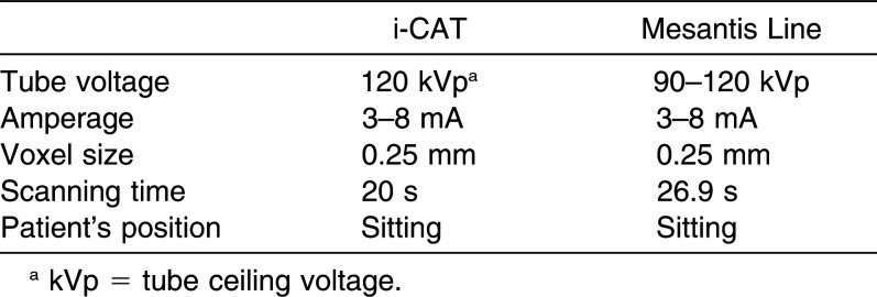
For the 431 CBCTs, we used the i-CAT (Imaging Sciences International, Hatfield, Pa) and the Mesantis line (special edition, Imaging Sciences International). Technical data are given in Table 2. All CBCTs were taken with standardized adjustments: brightness, 450 cd/qm, gray level (window: 3300; level: 950). Measurements were made with a regular, consistency-checked monitor according to category B (Eizo RadiForce GS 310, Eizo Corp, Kanazawa, Japan) of the quality control guidelines.
Table 2.
Technical Data of CBCT Devices Used
For the measurements, the CBCTs were edited as mulitplanar, reformatting digital imaging and communications in medicine files with InVivoDental 5.0 Software (Anatomage, San Jose, Calif).
Reference point 1 was the most apical point of the palatal CEJ of the maxillary central incisor of each side. Reference point 2 was defined as the intersection of the median sagittal plane and the posterior margin of the incisive foramen. Based on these reference points, a virtual measuring grid was placed on the palatal surface (Figure 1). All grid points lay on the median or paramedian sagittal plane with a distance of 10.00, 12.00, 14.00, 16.00, 18.00, and 20.00 mm, respectively, to reference point 1 of each side. The paramedian planes had a distance of 0.00, 2.00, 4.00, 6.00, and 8.00 mm, respectively, from the median sagittal plane to the right and left sides. The number of measurements resulted in five different factors (0.00–8.00 mm) and the equivalent factor level combinations. Therefore, there were 60 measuring points per patient. Subsequently, the single measuring points were abbreviated as R/L (right/left), X (distance in millimeters from the posterior margin of the incisive foramen to the right side), and Y (distance in millimeters from the most apical point of the palatal CEJ of the maxillary central incisor to the posterior).
Figure 2.
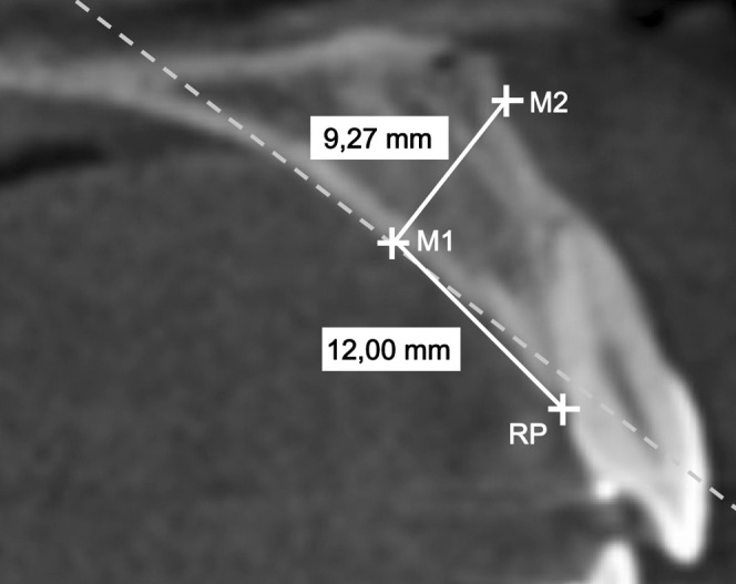
CBCT screenshot of the sagittal plane with the reference point (RP) at the cementoenamel junction (CEJ) of a maxillary central incisor and a measurement of the bone thickness 12.00 mm posterocranial of this RP, perpendicular to the bony surface. The dotted line is the tangent to the palatal contour in measurement point M1.
Figure 1.
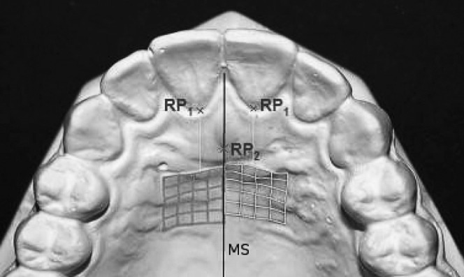
Schematic representation of the palatal reference and measurement points. RP1 = reference point 1, the most apical points of the CEJ of the left and right maxillary central incisor, respectively. RP2 = reference point 2, intersection of the median sagittal plane with the posterior bony surface of the incisive foramen. MS = median sagittal plane.
After we determined the grid points, the available bone thickness was measured to an accuracy of 0.01 mm perpendicular to the bony palatal surface by one investigator (Figure 2). The bone thickness was limited through dental roots, the nasal floor, the maxillary sinus, and the incisive canal.
The method error calculation was performed using Dahlberg’s formula15 and Houston’s reliability coefficient. Three randomly selected CBCTs were measured 15 times. As variance in homogeneity, the Mauchly test revealed that the Greenhouse-Geisser correction had been applied.16 For multiple comparisons, all P values and Sidak’s confidence intervals were adjusted to take account of the α-error accumulation.
Differences between single-factor levels and the most important interactions were reviewed with the univariate, multifactorial variance analysis with repeated measurements ( = inner subject factors). The inner subject factors describe the measurements in the mediolateral direction (five levels: 0.00–8.00 mm) and in the sagittal direction (6 levels: 10.00 –20.00 mm); gender (two levels: male, female) and age (three levels: 9–13 years, 14–18 years, 19–30 years) were the between-subject factors.
The four-level factorial design was used to determine whether there are any differences in bone thickness between measured points in the mediolateral and anteroposterior directions. We also wished to investigate differences in bone thickness between male and female patients and different age groups.
Differences between right and left sides were examined with the univariate, single-factor variance analysis, which included only the factor “side of the body” with two levels (right vs left).
Median values, standard deviations, and maximal and minimal bone-thickness measures were calculated.
RESULTS
Measurement precision was very high. Method error was calculated with Dahlberg’s formula as 0.38 mm and Houston’s reliability coefficient as 98.53%.
Descriptive statistics show that, in the median sagittal plane and posterior third of the virtual measuring grid, bone thickness was less than 7.0 mm. Table 3 shows the median values.
Table 3.
Color Coding of Bone Thickness 10–20 mm Posterior to the CEJ of the Maxillary Central Incisors and 0–8 mm Lateral to the Incisive Foramen of all Evaluated CBCTS, Mentioned as Median Value
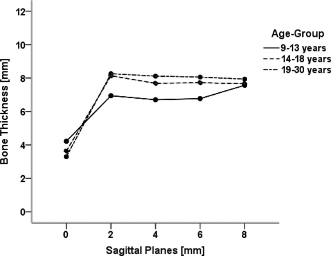
For a detailed specification of bone thickness in the various paramedian planes, multiple paired comparisons were made. Least mean bone thickness was measured in the median sagittal plane, which increased clearly 2.00 mm laterally (Figures 3 and 4).
Figure 3.
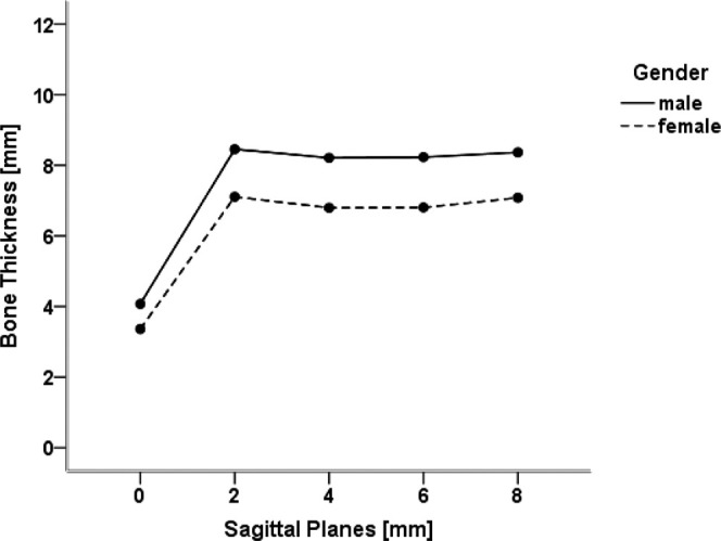
Interaction between the measurements in a medialolateral direction and the patient’s gender. Presented are the mean values of the bone thickness for both genders in the different sagittal planes. The values of the various measurement points in one sagittal plane are summarized.
Figure 4.
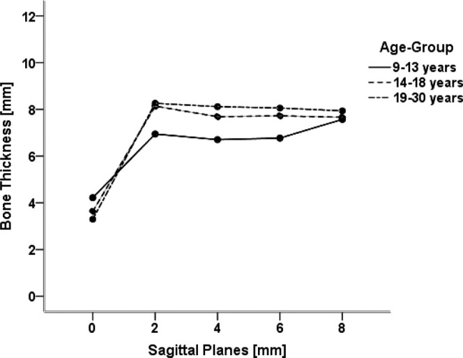
Interaction between the measurements in a mediolateral direction and the patient’s age. Presented are the mean values of bone thickness for all three age groups in the different sagittal planes. The values of different measurement points in one sagittal plane are summarized.
There were almost always significant differences between measured bone thicknesses in the anteroposterior direction. Initially, bone thickness increased to a maximum of 12.00 mm anterior and 14.00 mm posterior to the CEJ (Figures 5 and 6).
Figure 5.
Interaction between the measurements in the anterioposterior direction and the patient’s gender. Presented are the mean values of bone thickness for both genders in the different frontal planes. The values of the various measurement points in one frontal plane are summarized.
Figure 6.
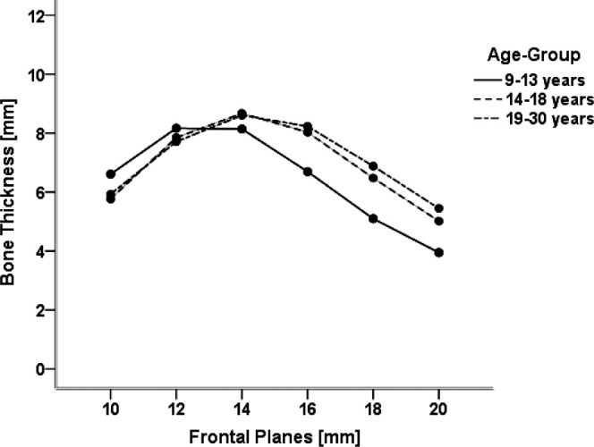
Interaction between measurements in the anteroposterior direction and the patient’s age. Presented are the mean values of bone thickness for all three age groups in the different frontal planes. Values of the various measurement points in one frontal plane are summarized.
In the median sagittal plane, bone thickness increased posteriorly. The bone thickness of all other sagittal planes showed similar characteristics, with a maximum at 12.00 mm anterior and 14.00 mm posterior to the CEJ, respectively (Figure 7).
Figure 7.
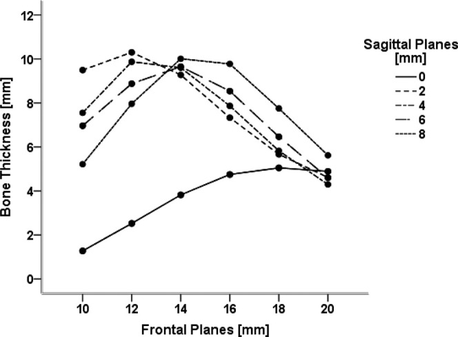
Interaction between measurements in the anteroposterior and mediolateral directions. Presented are the mean values of bone thickness for all sagittal planes in the anteroposterior direction. Values of right and left sides are summarized.
In male patients, bone thickness was significantly higher than in female patients, having on average 1.23 mm more thickness.
The difference between the male and female patients was in the median sagittal plane less than in the sagittal planes (Figure 3). There was an almost negative quadratic progress for both genders, with a maximum bone thickness of 14.00 mm posterior to the reference point (Figure 5).
Bone thickness of the 9–13-year-olds was on average 6.44 mm significantly smaller than that of the 14–18-year-old patients (6.96 mm) or the 19–30 group (6.99 mm). Between the 14–18 and 19–30-year-old patients, no significant differences could be determined.
The univariate, single-factor variance analysis with repeated measurements offered no significant difference between the right and left sides (P = .865).
DISCUSSION
To determine the ideal insertion point for an orthodontic miniscrew, the clinician must know bone thickness of the anterior palate. All evaluated CBCTs were taken for orthodontic reasons. Excluded were CBCTs with missing or unclear reference points or with mutated bone conditions. Authors of similar studies have chosen the same exclusion criteria.12–14,17
Several investigations have evaluated maxillary bone thickness for orthodontic miniscrews.12–14,17,18 However, in most studies, no gender- or age-related discrimination of the patients was made.12–14,17,18 To minimize variance and achieve maximum validity, it is important to create subdivisions. Due to pubertal growth, differing bone thicknesses in different age groups are expected. Gracco et al. divided their material into three age groups.14 In the present study, the CBCTs taken of 9- to 30-year-olds were divided into three age groups and two gender groups.
Bone thickness measurements were all determined in the sagittal plane. Some authors have chosen the same plane,12,17 while others used the frontal plane.13,14 Our measurements were made perpendicular to the bony surface to correlate with the recommended insertion direction of different authors.10 Additionally, in the measured region, the palate is more curved anteroposteriorly than mediolaterally. Therefore, it seems reasonable to evaluate bone thickness in the sagittal plane. Thus, this measurement may not reflect the real clinical situation. Since not all three dimensions were included, false-positive and -negative measurements were possible. Admittedly, other measurement planes might have produced different results. However, the choice of miniscrew insertion perpendicular to the bony surface or at an oblique angle depends on clinical preferences.
The radiological reference points and lines of former studies12–14,17,18 are clearly reproducible in CBCTs, but are not clearly defined clinically, because they are all bony reference points and herewith under the mucosa. The reference points of the present study can be easily determined clinically.
Because the CBCT voxel size was 0.25 mm, the measurements were made with an accuracy of 0.01 mm. Consequently, a minimal difference between measurements and real bone thickness was possible. Since the measurement accuracy cannot be more precise than 0.1 mm, Table 3 shows the measurements with only one decimal value. With a voxel size of 0.25 mm, the Nyquist frequency is ½ × 0.25 mm = 2 line pairs per mm [Lp/mm] = nominal maximum location resolution. Because of artifacts, the real accuracy is probably even worse. A realistic evaluation of measurement accuracy may be at most 0.5 mm.
Over 90% of all evaluated CBCTs exhibited ≥7.0 mm of bone thickness in the anterolateral two-thirds of the measured maxillary regions, which—having the recommended safety zone of 1.0 mm—is sufficient to accommodate a 6.0-mm miniscrew.19,20 Because of anatomical conditions, generally <7.0 mm of the median sagittal plane and posterior measurement third were evaluated. In the anteromedian region of the palate, the incisive foramen and canal run cranioposteriorly. When the measurement point was directly at the incisive foramen, the measured bone thickness was 0.00 mm. In the posterior region, the maxillary bone becomes thinner. However, the nasal septum, which is cranialward of the median palatal suture, would lead one to expect a greater bone thickness. In order to explain why the present study suggests the opposite, it would have been necessary to evaluate not only the bone thickness, but also the limiting factors.
Our findings correspond only partially with the results of other authors. Henriksen et al.8 and Ludwig et al.10 recommend inserting orthodontic miniscrews in the median sagittal plane. Kyung et al.9 recommend the same for mini-implants. Kang et al. analyzed bone thickness and found the maximum values in the median sagittal plane.17 Whether this result is due to the fact that they chose only nonorthodontic patients without any skeletal or dental asymmetries can only be speculated.17 Furthermore, Kang et al.17 did not measure perpendicular to the bony surface, but perpendicular to a constructed plane. Penetration of a miniscrew into the cavum nasi does not influence its primary stability,6 but for forensic reasons it might be problematic. As measured in the present study, numerous other authors found the thickest bone in the paramedian plane.12–14,18
Since the quality of bone is also crucial for primary stability, in future studies the available CBCTs should be investigated by means of the Vercelotti and Vercelotti bone classification.21 Asscherickx et al. could not exclude the possibility that a median sagittal insertion influences growth.11 Since Wilmes et al. noticed no growth retardation after inserting numerous miniscrews in the median sagittal suture,22 the risk of growth retardation seems to be small.
Our results of gender comparison only partially confirm previous studies. Gracco et al. found no statistically relevant difference in bone thickness between male and female patients. One reason could be that these authors made their measurements in another plane.13,14 Both King et al.12 and Kang et al.17 confirm the results of the present study, namely, that males have thicker bone.
When we compared different age groups, we found that there was no clinically relevant difference between patients aged 14–18 vs 19–30 years. This can be explained by the maxillary growth that ends at age 15.23 However, not all the median values of the 9–13 group were smaller than those of the older patients. The 9–13-year-olds exhibited thicker bone in the anterior and median regions. At these ages, the maxilla is in total smaller, but the distance of the measurement points is the same. Therefore, the incisive foramen and canal in the youngest age group are probably anterior to the measurement region, while in older patients with a larger maxilla, these anatomical structures fall within the measurement region. One possible explanation for the varying bone thickness between age groups may that the roots of the canines and premolars are still growing. Another reason could be the appositional growth of the maxilla ending at age 14, while nasal resorption continues.22
No clinically relevant difference between left and right sides could be determined, which agrees with other authors.12–14,17
CONCLUSIONS
Bone thickness of female patients is on average 1.23 mm less than that of male patients.
Long miniscrews should not be inserted in the median sagittal plane, because less bone thickness is available in this region.
It is recommended that placement of orthodontic miniscrews should be made in different regions according to patient’s age.
Inasmuch as there is not always sufficient bone thickness (≥7.0 mm) due to individual variation, a CBCT is justified before inserting a palatal orthodontic miniscrew.
REFERENCES
- 1.Maschinski G, Hasenau T, Illig U. Lexikon Zahnmedizin Zahntechnik. Munich Germany Urban & Fischer. 2000;406:786–787. [Google Scholar]
- 2.Lietz T, Müller-Hartwich R. Zahnerhaltung durch kieferorthopädische Maßnahmen. ZWR. 2006;115:91–102. [Google Scholar]
- 3.Gray J, Steen M, King G, Clark AE. Studies on the efficacy of implants as orthodontic anchorage. Am J Orthod. 1983;83:311–317. doi: 10.1016/0002-9416(83)90226-9. [DOI] [PubMed] [Google Scholar]
- 4.Buechter A, Wiechmann D, Koerdt S, Wiesmann HP, Pfiffko J, Meyer U. Load-related implant reaction of mini-implants used for orthodontic anchorage. Clin Oral Impl Res. 2005;16:473–479. doi: 10.1111/j.1600-0501.2005.01149.x. [DOI] [PubMed] [Google Scholar]
- 5.Hembree M, Buschang P, Carrillo R, Spears R, Rossouw PE. Effects of intentional damage of the roots and surrounding structures with miniscrew implants. Am J Orthod Dentofacial Orthop. 2009;135:280.e1–e9. doi: 10.1016/j.ajodo.2008.06.022. [DOI] [PubMed] [Google Scholar]
- 6.Kravitz ND, Kusnoto B. Risks and complications of orthodontic miniscrews. Am J Orthod Dentofacial Orthop. 2007;131:43–51. doi: 10.1016/j.ajodo.2006.04.027. [DOI] [PubMed] [Google Scholar]
- 7.Kuroda S, Yamada K, Deguchi T, Hashimoto T, Kyung HM, Takano-Yamamoto T. Root proximity is a major factor for screw failure in orthodontic anchorage. Am J Orthod Dentofacial Orthop. 2007;131:68–73. doi: 10.1016/j.ajodo.2006.06.017. [DOI] [PubMed] [Google Scholar]
- 8.Henriksen B, Bavitz B, Kelly B, Harn SD. Evaluation of bone thickness in the anterior hard palate relative to midsagittal orthodontic implants. Int J Oral Maxillofac Implants. 2003;18:578–581. [PubMed] [Google Scholar]
- 9.Kyung SH, Hong SG, Park YC. Distalization of maxillary molars with a midpalatal miniscrew. J Clin Orthod. 2003;37:22–26. [PubMed] [Google Scholar]
- 10.Ludwig B, Glasl B, Bowman SJ, Wilmes B, Kinzinger G, Lisson J. Anatomical guidelines for miniscrews insertion: Palatal sites. J Clin Orthod. 2011;45:433–441. [PubMed] [Google Scholar]
- 11.Asscherickx K, Hanssens JL, Wehrbein H, Sabzevar MM. Orthodontic anchorage implants inserted in the median palatal suture and normal transverse maxillary growth in growing dogs: a biometric and radiographic study. Angle Orthod. 2005;75:826–831. doi: 10.1043/0003-3219(2005)75[826:OAIIIT]2.0.CO;2. [DOI] [PubMed] [Google Scholar]
- 12.King KS, Lam EW, Faulkner MG, Heo G, Major PW. Vertical bone volume in the paramedian palate of adolescents: a computed tomography study. Am J Orthod Dentofacial Orthop. 2007;132:783–788. doi: 10.1016/j.ajodo.2005.11.042. [DOI] [PubMed] [Google Scholar]
- 13.Gracco A, Lombardo L, Cozzani M, Siciliani G. Quantitative evaluation with CBCT of palatal bone thickness in growing patients. Prog Orthod. 2006;7:164–174. [PubMed] [Google Scholar]
- 14.Gracco A, Luca L, Cozzani M, Siciliani G. Assessment of palatal bone thickness in adults with cone beam computerised tomography. Aust Orthod J. 2007;23:109–113. [PubMed] [Google Scholar]
- 15.Houston WJB. The analysis of errors in orthodontic measurements. Am J Orthod. 1983;83:382–390. doi: 10.1016/0002-9416(83)90322-6. [DOI] [PubMed] [Google Scholar]
- 16.Buehl A, Zoefel P. SPSS 12 Einführung in die moderne Datenanalyse 9 Auflage. Munich, Germany: Pearson Studium; 2005. [Google Scholar]
- 17.Kang S, Lee SJ, Ahn SJ, Heo MS, Kim TW. Bone thickness of the palate for orthodontic mini-implant anchorage in adults. Am J Orthod Dentofacial Orthop. 2007;131:74–81. doi: 10.1016/j.ajodo.2005.09.029. [DOI] [PubMed] [Google Scholar]
- 18.Bernhart T, Vollgruber A, Gahleitner A, Doertbudak O, Haas R. Alternative to the median region of the palate for placement of an orthodontic implant. Clin Oral Impl Res. 2000;11:595–601. doi: 10.1034/j.1600-0501.2000.011006595.x. [DOI] [PubMed] [Google Scholar]
- 19.Poggio PM, Incorvati C, Velo S, Carano A. “Safe zones”: a guide for miniscrew positioning in the maxillary and mandibular arch. Angle Orthod. 2006;76:191–197. doi: 10.1043/0003-3219(2006)076[0191:SZAGFM]2.0.CO;2. [DOI] [PubMed] [Google Scholar]
- 20.Schnelle MA, Beck FM, Jaynes RM, Huja SS. A radiographic evaluation of the availability of bone for placement of miniscrews. Angle Orthod. 2004;74:832–837. doi: 10.1043/0003-3219(2004)074<0832:AREOTA>2.0.CO;2. [DOI] [PubMed] [Google Scholar]
- 21.Vercellotti T, Vercellotti G. New bone classification for analysis of the single surgical site. In: Vercellotti T, editor. Essentials in Piezosurgery Clinical Advantages in Dentistry. Milan, Italy: Quintessence; 2009. pp. 91–93. [Google Scholar]
- 22.Wilmes B, Drescher D, Nienkemper M. A miniplate system for improved stability of skeletal anchorage. J Clin Orthod. 2009;70:297–305. [PubMed] [Google Scholar]
- 23.Melsen B. Palatal growth studied on human autopsy material. Am J Orthod. 1975;68:42–54. doi: 10.1016/0002-9416(75)90158-x. [DOI] [PubMed] [Google Scholar]


