Abstract
Many implantable electrode arrays exist for the purpose of stimulating or recording electrical activity in brain, spinal, or peripheral nerve tissue, however most of these devices are constructed from materials that are mechanically rigid. A growing body of evidence suggests that the chronic presence of these rigid probes in the neural tissue causes a significant immune response and glial encapsulation of the probes, which in turn leads to gradual increase in distance between the electrodes and surrounding neurons. In recording electrodes, the consequence is the loss of signal quality and, therefore, the inability to collect electrophysiological recordings long term. In stimulation electrodes, higher current injection is required to achieve a comparable response which can lead to tissue and electrode damage. To minimize the impact of the immune response, flexible neural probes constructed with softer materials have been developed. These flexible probes, however, are often not strong enough to be inserted on their own into the tissue, and instead fail via mechanical buckling of the shank under the force of insertion. Several strategies have been developed to allow the insertion of flexible probes while minimizing tissue damage. It is critical to keep these strategies in mind during probe design in order to ensure successful surgical placement. In this review, existing insertion strategies will be presented and evaluated with respect to surgical difficulty, immune response, ability to reach the target tissue, and overall limitations of the technique. Overall, the majority of these insertion techniques have only been evaluated for the insertion of a single probe and do not quantify the accuracy of probe placement. More work needs to be performed to evaluate and optimize insertion methods for accurate placement of devices and for devices with multiple probes.
Keywords: flexible neural probes, flexible microelectrode array, neural probe insertion, brain–machine interfaces
1. Introduction
Over the past several decades, brain–machine interfaces (BMIs), which communicate with the brain via electrical activity, have been integral in advancing knowledge of the brain’s functions. A variety of BMIs have been developed to interface with the brain in different ways (see figure 1). As surgical technique has advanced, BMIs have been able to interface more closely with brain tissue to provide greater clinical benefits and to answer more complex research questions.
Figure 1.
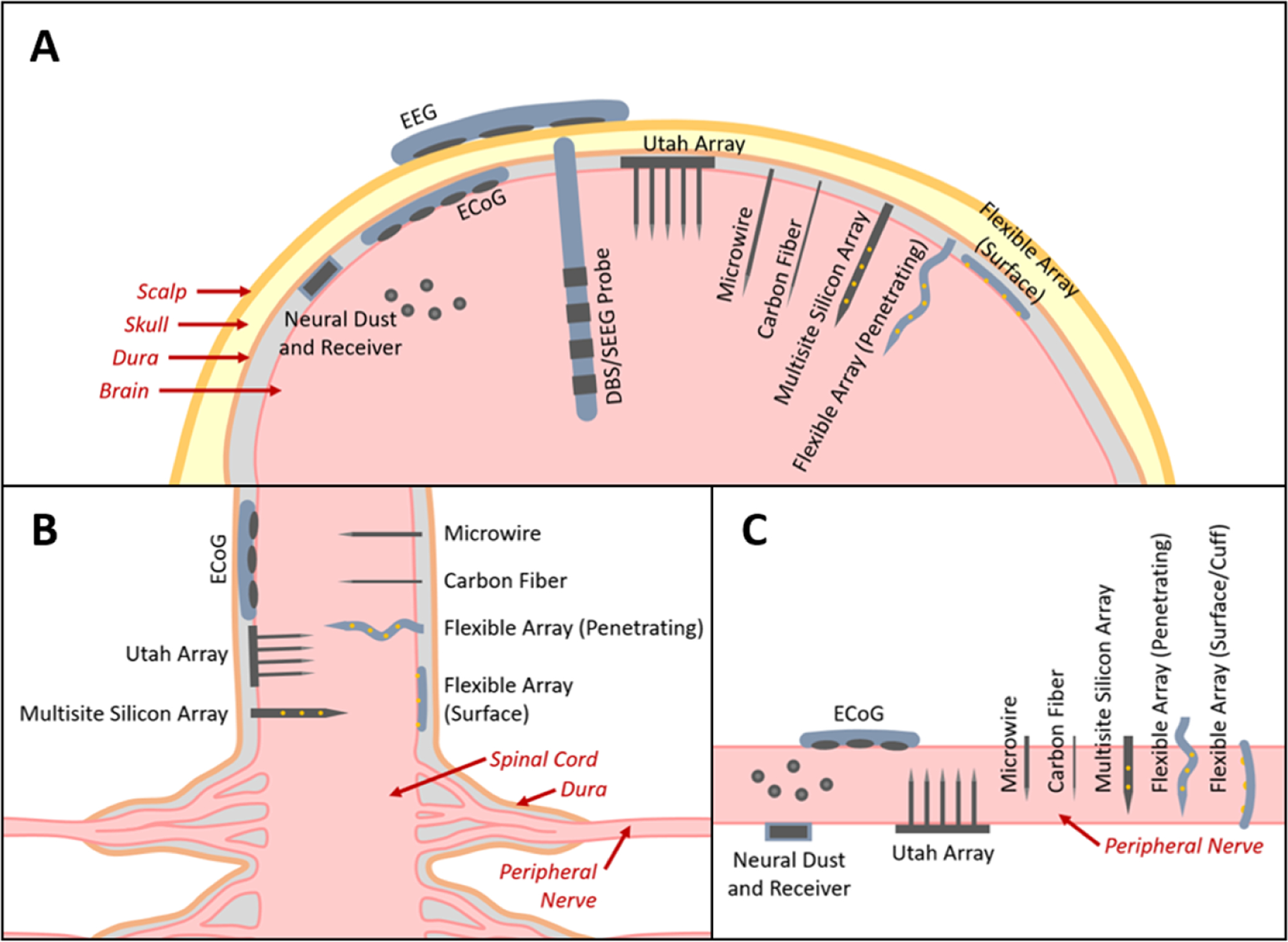
The major types of BMI electrode interfaces in (A) brain, (B) spinal cord, and (C) peripheral nerve (figures not to scale). EEG electrodes are placed on the scalp. ECoG electrodes are placed subdurally. DBS and SEEG probes are implanted into deep brain tissue. Neural dust are micron-scale devices containing microelectrodes and passive electronics placed directly into the brain tissue and work in conjunction with a wireless receiver (note: these have not yet been demonstrated in brain tissue, only on the outer surface of spinal tissue). The Utah array contains regularly arranged tines each having a single electrode site at the tip. These penetrating probes are typically 1–2 mm long. Microwires and carbon fibers are penetrating probes each with a single electrode site at the tip that can extend several millimeters long allowing access to deeper brain regions and are also available as arrays. Multisite silicon arrays and flexible arrays are probes with arrays of microelectrodes that can also extend several millimeters long, but are distinguished from the other types of penetrating microelectrodes in that the probe supports multiple microelectrodes along its length, allowing greater access to brain regions at multiple depths. Flexible arrays can also be placed on the surface of the tissue to act similarly to ECoG electrodes.
The earliest reports of electrical activity in the brain date back to the 1870s when several groups noted responses during electrical stimulation of exposed brain tissue in various animal models. This research inspired the work of Hans Berger who coined the term electroencephalogram (EEG) in 1929 after recording electrical activity in the human brain through the scalp and skull. Ten years later, Wilder Penfield and Herbert Jasper performed the first ‘invasive EEG’ by placing electrodes directly on the brain surface, which would later be termed electrocorticography (ECoG). In 1949, Robert Hayne and Russel Meyers implanted a plastic rod with ring-shaped electrodes around the circumference into the brain tissue, which lead to the development of stereo-electroencephalography (SEEG) and deep brain stimulation (DBS) electrodes—the most commonly used types of penetrating electrodes today [1–3]. Shortly after the development of modern SEEG and DBS electrodes, the first reports of spinal cord stimulation and peripheral nerve stimulation (via electrodes placed on the surface of the tissue) were published in 1967 [4].
In parallel to the development of clinical electrode arrays, researchers employed electrodes in various animal models for electrophysiological recording and stimulation. However, due to the relatively small size of common animal models in nervous system research (see figure 2 for brain sizes of common animal models), separate probes were concurrently developed for clinical human use (such as SEEG and DBS probes, with diameters ranging from 0.86 to 1.27 mm and electrodes along a 10–20 mm length of the probe [5, 6]) and for animal research use (such as microwires, with diameters ranging from 25 to 80 μm and a single electrode site at the tip [7–11]).
Figure 2.
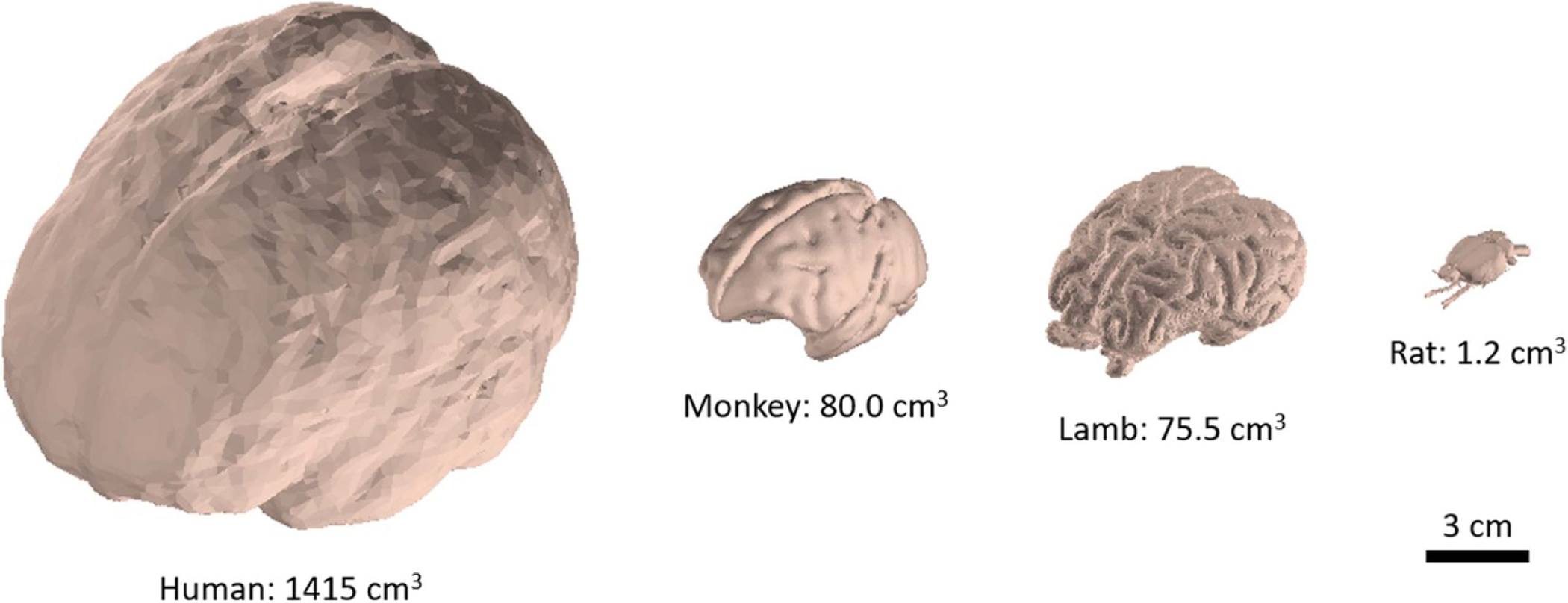
Brain sizes for human and common animal models. Rhesus monkey, lamb and rat have approximately 5.7%, 5.4%, and 0.1% of the brain volume of humans respectively [12–17].
Beginning in the 1950s, researchers began using metallic microwires (micron-scale insulated wires with an exposed tip) for single unit recording (recording from a single neuron). In order to record from multiple sites at once in the same region, arrays of closely-spaced microwires were assembled and implanted together. This need for higher density recording led to the invention of multisite silicon arrays (planar, silicon arrays with multiple thin film electrodes patterned along the length of each probe) in 1985 and the Utah array (a microfabricated array of needle-like electrodes) in 1991 [18, 19]. Today, many penetrating arrays are available commercially for use in the brain, spinal cord, and peripheral nerves. The most sophisticated of these are silicon-based probe assemblies that integrate microelectronics, such as the Utah [20] and Neuronexus [21] array assemblies.
The body’s immune response (discussed later in this review) poses challenges for implanted electrode design and their ability to achieve long term recording. After any foreign body is inserted into tissue, a sheath of scar tissue forms around the foreign material over the course of several weeks. The scar tissue increases the distance between the electrode sites and the neural tissue, making it more difficult to effectively record or efficiently stimulate. Recently, to mitigate the effect of this immune response and enable a more stable electrode-tissue interface and distance over longer periods of time, the focus has turned to microfabricated multisite arrays fabricated from softer, more flexible supporting materials, such as polymers, with mechanical properties more closely matching that of neural tissue. Several groups have reviewed the evolution of intracortical [18, 22, 23], subdural [24] and penetrating [25] spinal, and intrafascicular [26, 27] probes over time and emphasized the advantages of using flexible materials [18, 22, 23].
The implementation of flexible electrodes, however, faces a more pronounced challenge during the surgical insertion procedure. Flexibility may be gained by using small diameter fibers, thinning the supporting silicon in a multisite array, or using a soft polymer material to construct a probe. In particular, flexible polymer probes tend to lack the axial strength to resist mechanical buckling during insertion into tissue, making it difficult to reliably implant them to the intended target. This has prompted the development of many insertion techniques and strategies. The most commonly used insertion methods for flexible probes are discussed in this review. An overview of rigid clinical and research probes is also provided in the following section as a reference to compare the difficulty of inserting flexible probes and to provide examples of potential clinical and research applications.
2. Current penetrating clinical and research probes
To place the insertion challenges associated with flexible probes into context, methods to surgically place rigid penetrating probes are first presented. Although the major focus of this article is on flexible devices used for research purposes, rigid clinical and research probes are included in this section to provide historical context and for comparison. A summary of rigid clinical and research probes is provided in table 1. This section includes rigid probes with larger electrodes (millimeter scale and larger) and microelectrodes (micron scale and smaller). This brief background provides a foundation for the discussion of flexible probes later in this review.
Table 1.
Properties of existing rigid and flexible electrodes.
| Device | Type | Location | Probe size | Electrode size | Recording signal type/frequencya | Human/animal useb |
|---|---|---|---|---|---|---|
| Scalp EEG [19, 28] | Surface (scalp) | Brain | N/a | 4–10 mm diameter | Large neuronal population (<70 Hz) | Human |
| ECoG [19, 29–31] | Surface (subdural) | Brain, peripheral nerve, spinal cord | N/a | 2–4 mm diameter | Local neuronal population (10–200 Hz) | Human |
| DBS and SEEG [5, 6, 29, 32, 33] | Penetrating | Brain | 0.86–1.27 mm diameter (wire) | 1.3–2.4 mm rings around probe diameter | LFP (<250 Hz) | Human, NHP |
| Microwires [7–9, 19, 25, 34] | Penetrating | Brain, peripheral nerve, spinal cord | 25–80 μm diameter (wire) | 0–20 μm exposed tip length | Single units (300–5000 Hz) | Rodent, larger mammal, NHP |
| Carbon fibers [35–42] | Penetrating | Brain, peripheral nerve, spinal cord | 3.5–40 μm diameter (wire) | 0–250 μm exposed tip length | Single units (300–5000 Hz) | Rodent |
| Utah array [10, 19, 20, 43–45] | Penetrating | Brain, peripheral nerve, spinal cord | 80 μm diameter (tapered to point) | 50 μm exposed tip length | Single units (300–5000 Hz) | Rodent, larger mammal, NHP, human |
| Multisite silicon [10, 19, 21, 46–50] | Penetrating | Brain, peripheral nerve, spinal cord | 120–200 × 15–50 μm (tapered to point) | 10–30 μm diameter | Single units (300–5000 Hz) | Rodent, larger mammal, NHP |
| Neural dust [51–53] | Penetrating (untethered) | Brain (theoretical), peripheral nerve | 0.8 × 3 × 1 mm (10–100 μm cube theoretical size) | 0.2 × 0.2 mm (1–5 μm diameter theoretical size) | LFP (<250 Hz) and Single units (300–5000 Hz) | Rodent (peripheral nerve) |
| Flexible arrays [18, 54–63] | Penetrating, surface | Brain, peripheral nerve, spinal cord | 10–554 × 1–30 μm (tapered to point) | 10–55 μm diameter | Single units (300–5000 Hz) | Rodent, larger mammal, NHP |
LFP = local field potential.
NHP = non-human primate
2.1. Stereoelectroencephalography and deep brain stimulation probes
SEEG and DBS probes (figure 3) are long, cylindrical tubes with an outer diameter of approximately 0.86–1.27 mm [5, 6]. The leads typically have 4–10 ring-shaped electrodes wrapping around the outer diameter of the lead with a height of 1.3–2.5 mm [6, 29, 32]. Some SEEG probes also contain microelectrodes either on the tip of the probe or radially spaced around the body of the probe to allow for more accurate spatial mapping of electrophysiological signals [29]. Most SEEG and DBS probes are made of platinum or platinum/iridium wires surrounded by a non-conductive polymeric insulation [29, 64, 65]. Several SEEG and DBS devices are clinically approved for the diagnosis and treatment of epilepsy (the neuropace system for epilepsy treatment is shown in figure 4) and various movement disorders such as Parkinson’s disease and essential tremor [5, 29, 32, 33, 66, 67]. SEEG/DBS probes are also regularly used in research settings for diagnosis and treatment of other neurological conditions [64, 65, 68]. Because of their relatively large size, these devices are generally only used in humans, however a scaled down version of the device has been tested in non-human primates (NHP) [33]. The large size also causes the displacement of a large amount of tissue which has been found to cause irreversible damage to the brain tissue [64].
Figure 3.
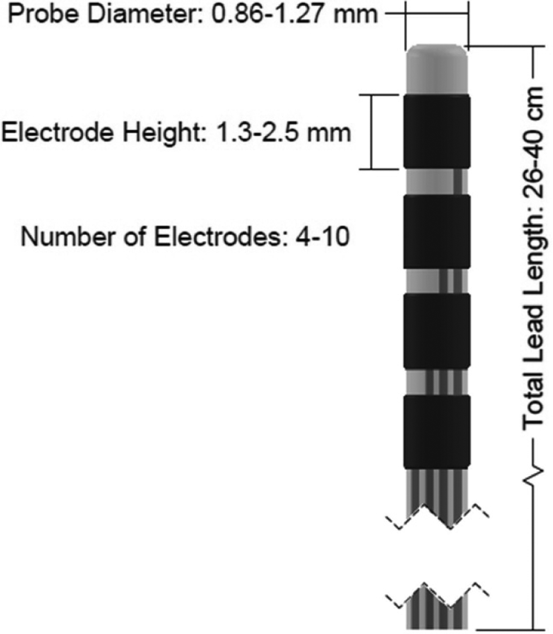
Diagram of a DBS or SEEG probe. Dimensions sourced from [6, 29, 32].
Figure 4.
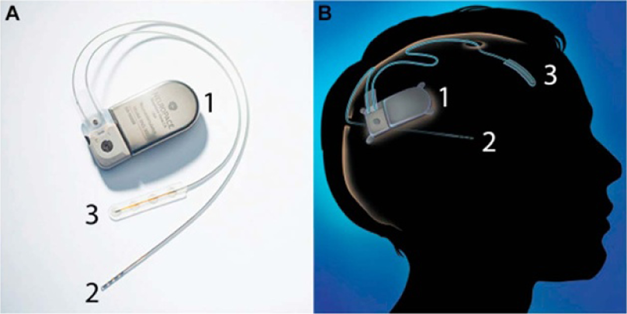
The neuropace responsive neurostimulation (RNS) system which consists of a pulse generator (1), a DBS probe with four ring-shaped electrodes (2) and a subdural ECoG probe with four circular electrodes (3). The left image (A) shows the device, and the right image (B) shows a diagram of the fully implanted device. Reprinted from [69], Copyright (2015), with permission from Elsevier.
To insert SEEG or DBS leads, the patient’s head is mounted in a stereotactic frame and aligned with the pre-operative magnetic resonance imaging (MRI) and/or computerized tomography (CT) scans (if available). A burr hole is drilled above the implantation site, and the dura is incised [5, 66, 67]. The lead is then aligned using the frame and inserted into the tissue manually [5, 6, 33, 64, 68]. In DBS surgeries, basic wire electrodes (with a diameter of 0.5–1 mm and a single electrode at the tip) are sometimes inserted prior to inserting the DBS probe to determine the best possible implant location [70, 71]. Recently, frameless insertion techniques have been evaluated, however these are not as commonly used in clinical settings [5, 67]. The overall size of the probe and stiffness of the wires makes the probe rigid enough to directly penetrate the tissue without buckling, however the polymeric insulation does allow the probe to flex when sufficient force is applied. Rigid materials can be inserted with the probe to ensure straight insertion and placement at the desired location. One such method is when a rigid cannula is inserted up to (but not through) the target region and the probe is advanced through the cannula. Once the probe reaches its target, the cannula is removed [66]. Alternately, the probe can contain a hollow center inside which a rigid stylet is placed during insertion. The stylet is then removed once the probe is in place [65]. Another common method is to insert a rigid stylet up to the target region (creating a ‘track’ from the insertion site to the target), remove it, then insert the SEEG or DBS probe along the same track [5]. These insertion techniques are able to achieve a location accuracy (distance between the implanted location and planned location) between 1.6 and 5.0 mm (mean values, with full range of 0.9–6.9 mm) [5, 66, 67].
2.2. Microwires
Microwires (figures 5 and 6) are long cylindrical wires, but with a much smaller outer diameter (as compared to SEEG and DBS probes) ranging from 25 to 80 μm [7–11]. Each microwire is a single, insulated wire (only one electrode per wire) with an exposed tip for stimulation or recording. Arrays of microwires can be assembled for higher density recording (figure 7) [8]. Most commonly, the wires are made of tungsten [7, 46], platinum [9], or platinum/iridium [8, 46] with an insulating coating of polyimide [7] or parylene C [8, 9]. The small exposed tip is sized for recording single unit signals [19]. These devices (single microwires and arrays of microwires) can be used in larger mammals, NHP, and in rodents because of their small size [7, 8, 34]. Currently, no commercial microwires are approved for human use, however there are larger wire electrodes (which have a similar architecture to microwires with a larger diameter of 0.5–1 mm) that are approved and often used in DBS surgeries to determine the optimal location for DBS probes [70, 71]. As compared to SEEG/DBS probes, the smaller size of microwires displaces a smaller amount of tissue, reducing the accompanying immune response [46].
Figure 5.
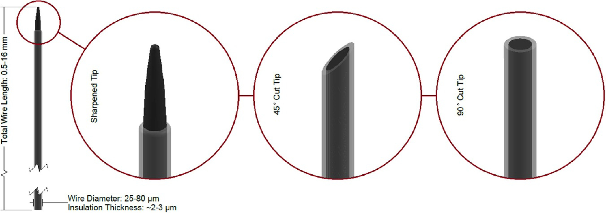
Diagram of a microwire with three common tip geometries shown. Dimensions sourced from [8–11].
Figure 6.
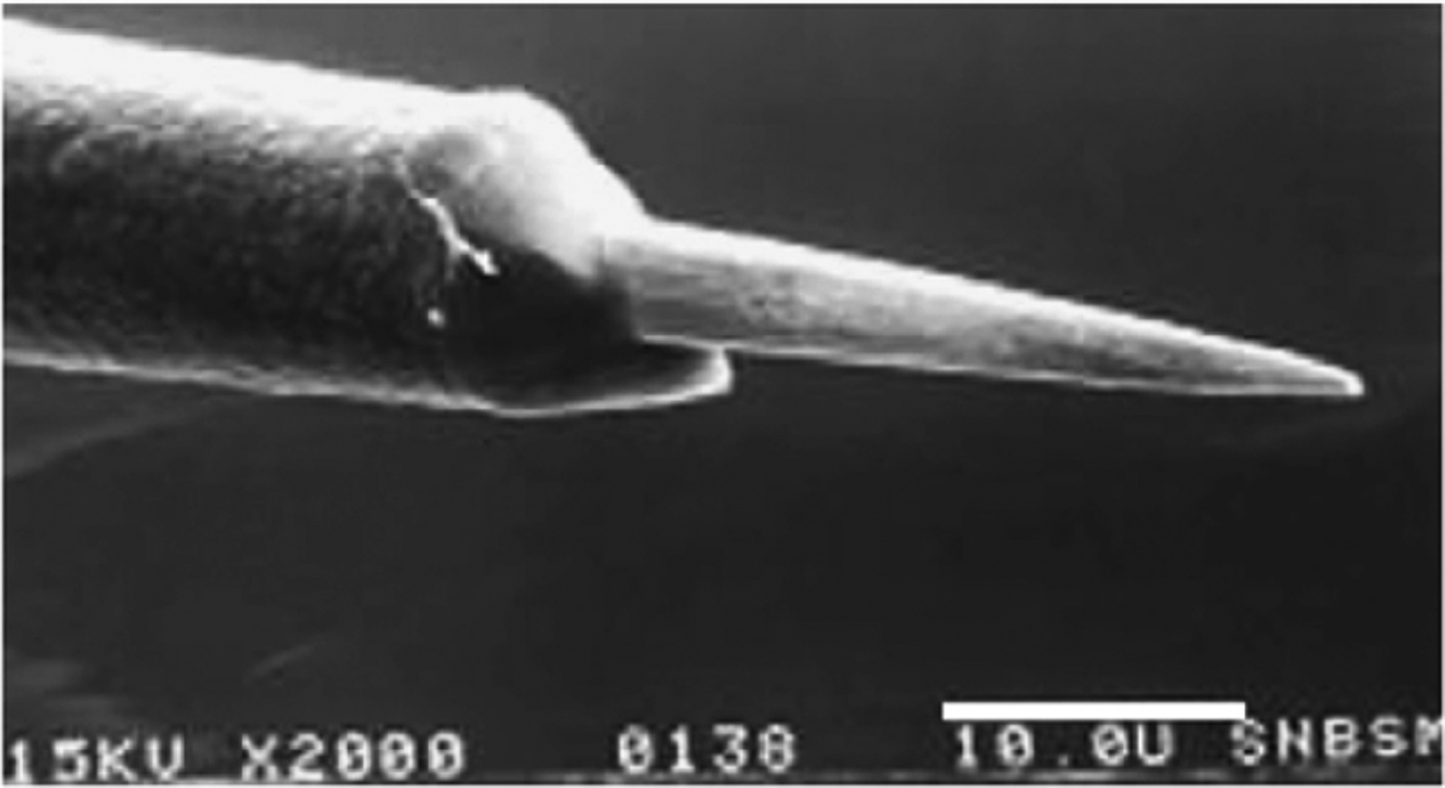
SEM image of a microwire probe tip. A 70%/30% platinum/iridium wire is electrochemically sharpened (producing the pointed tip), then coated with parylene C. After coating, the electrode tip is exposed using laser etching. Reprinted from [8], Copyright (2007), with permission from Elsevier.
Figure 7.
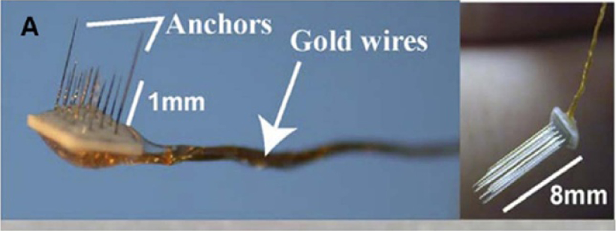
Two microwire arrays of different lengths consisting of 18 microwire probes. Reprinted from [8], Copyright (2007), with permission from Elsevier.
Early researchers inserted microwires in the same way as SEEG/DBS leads (manual insertion with or without a stereotactic frame) [8]. Today, this method is still in use, however they are also often inserted with a motorized insertion tool mounted to a frame [7]. Alternately, insertion tools or other methods used for flexible arrays (discussed later in this review) can be used with finer, more flexible microwires [9, 35]. In some cases, the dura is incised or removed prior to inserting the microwire [7, 8, 35], however some groups have had success inserting microwires through the intact dura [7, 9].
2.3. Carbon fibers
Carbon fibers (figures 8 and 9) are very similar in shape, construction, and function to microwires. They are small, cylindrical, fibers with an exposed tip ranging from 3.5 to 40 μm in diameter, usually coated in glass, parylene C, or another insulating polymer. Each fiber contains only a single electrode sized for recording single units [35–40, 72]. As with microwires, arrays of carbon fibers can be used for high density recording (figure 10) [35, 72]. Carbon fibers are primarily used in rodents due to their size.
Figure 8.
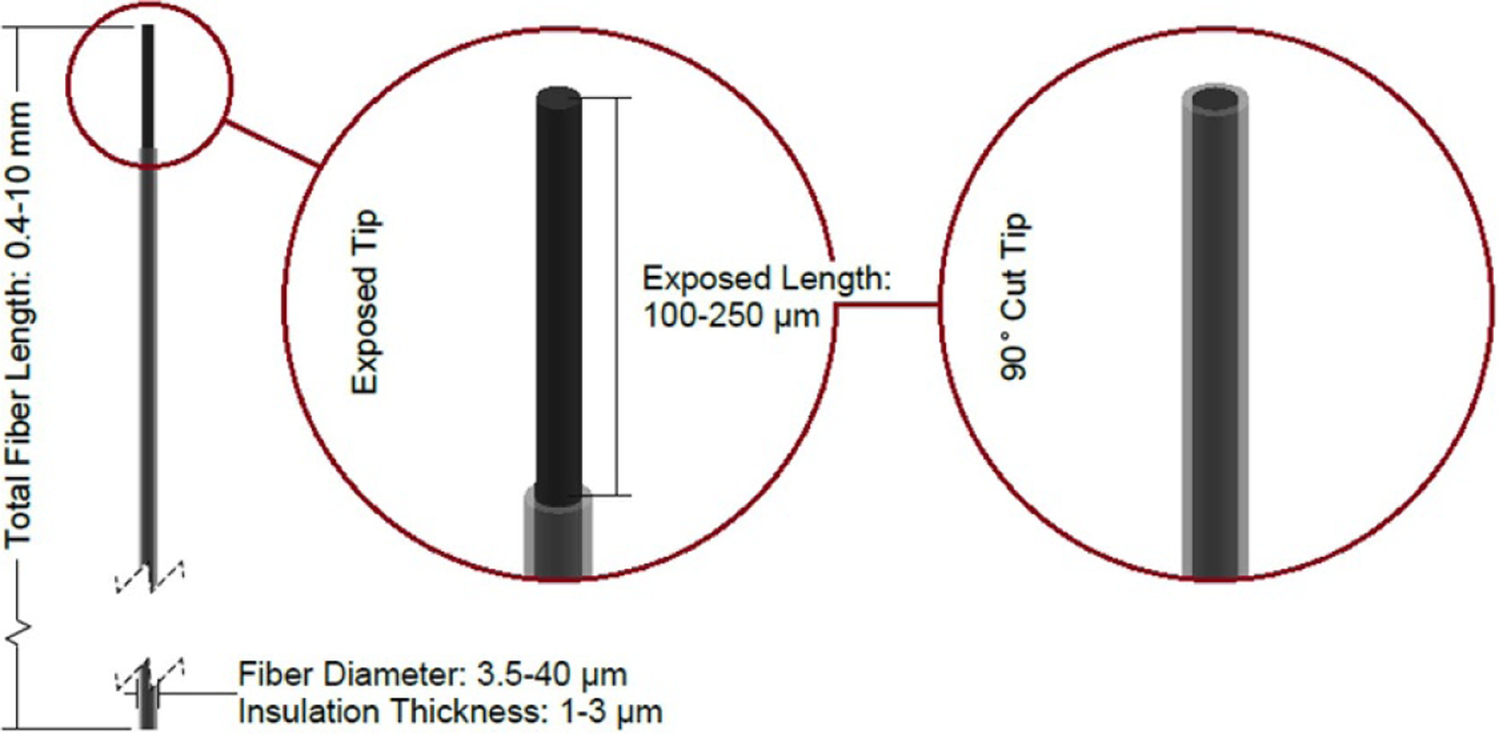
Diagram of a carbon fiber probe with two common tip geometries shown. Dimensions sourced from [35–40].
Figure 9.

SEM image of a glass-coated carbon fiber. These fibers are coated using a glass pulling process, then the exposed end of the fiber is cut to a predetermined length. In this case, the exposed carbon fiber electrode has been coated with platinum nanoparticles, producing a textured electrode surface. Reprinted from [36], Copyright (2019), with permission from Elsevier.
Figure 10.
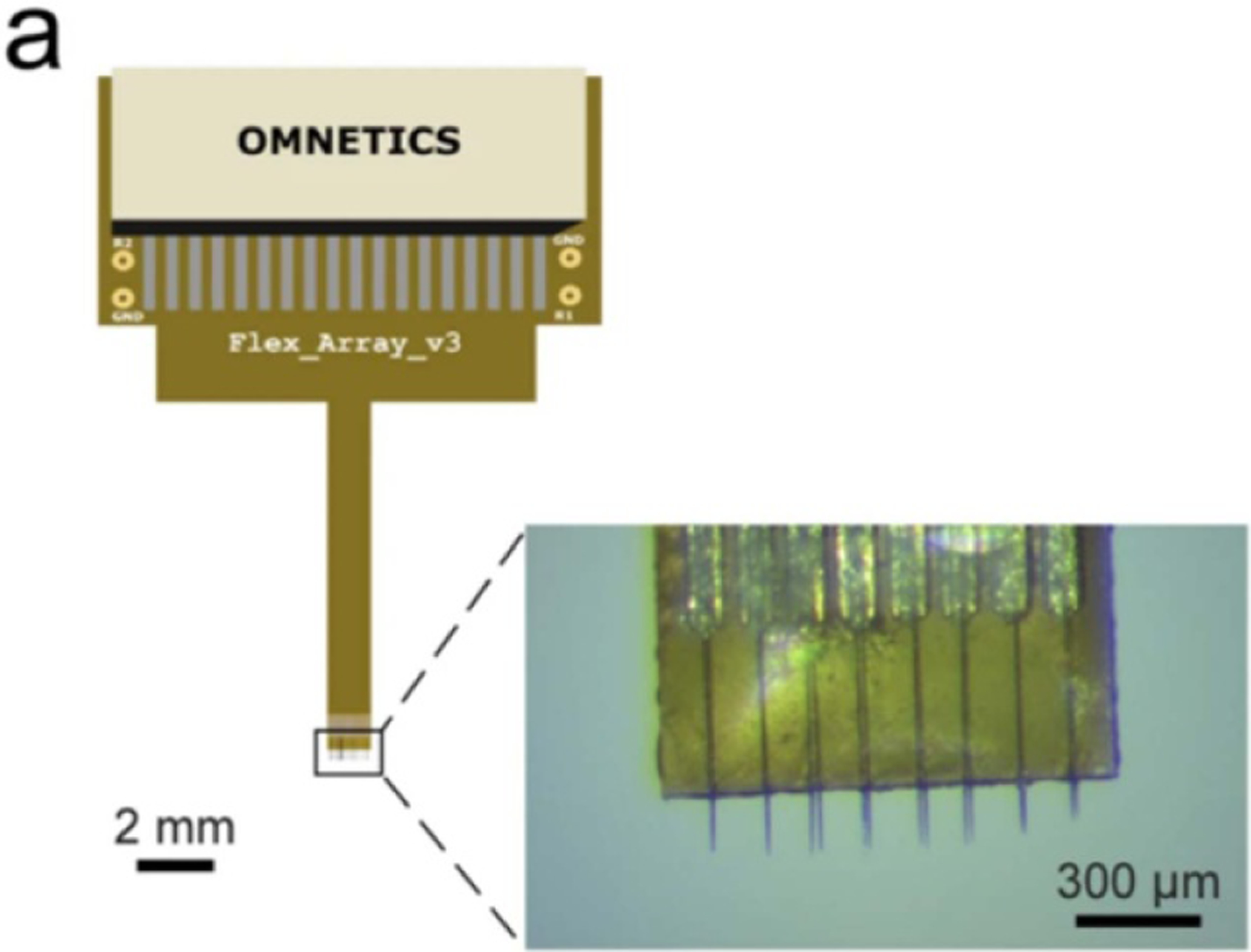
A 2 × 8 array of carbon fiber electrodes. Reprinted by permission from Springer Nature Customer Service Centre GmbH: Nature, Sci. Rep [72]. (c) 2020.
As with microwires, carbon fibers can be inserted manually or with a motorized drive via a stereotactic frame, or by using other insertion methods commonly used for flexible probes [35, 38, 40]. Due to the smaller size of carbon fibers, the dura is generally incised or removed prior to insertion to prevent buckling [35, 39].
2.4. Utah arrays
Utah arrays (figures 11 and 12) are arrays of up to 256 needle-like silicon electrodes on a single rigid platform [20]. Each electrode shank is approximately 80 μm in diameter at the base, tapered down to a point with a single electrode at its tip. The overall platform for the most commonly used array (100 electrodes) is 4.2 × 4.2 mm [43, 44]. The electrodes are sized for single unit recording. Utah arrays are most commonly used in large mammals and NHP [20, 43], although a scaled down version of the device (with fewer electrodes) can be used in rodents [45]. A fully packaged device consisting of a Utah array, cable (figure 13), and skull-mounted connector called the Neuroport array is approved for human use by the FDA as an investigational device [20, 73]. Although each electrode shank is relatively small (as compared to other clinical devices), the shanks are closely grouped together, so the initial immune response is increased compared to single wires (as evidenced by steep impedance spikes in the first few days following implantation and a slow impedance rise starting 1 week post-implant). Although the impedance is higher for Utah arrays as compared to microwires (indicating a higher degree of glial encapsulation), the signal to noise ratio of recordings for the two types of probes is comparable over time [10].
Figure 11.
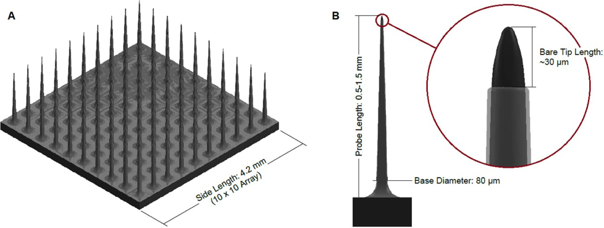
Diagram of a Utah array. (A) Shows a full 10 × 10 array, and (B) shows a single probe of a Utah array with a detail view of the exposed electrode tip. Dimensions sourced from [20, 44, 74].
Figure 12.
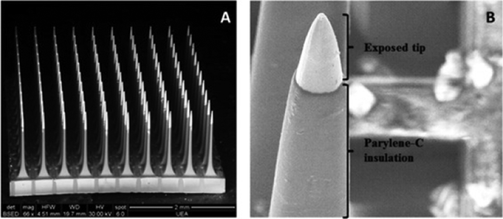
SEM images of a Utah array containing 100 electrodes of 1.5 mm length. (A) Shows the entire 10 × 10 electrode array, and (B) shows a detailed image of the exposed electrode tip and insulated probe. Reprinted from [75], Copyright (2016), with permission from Elsevier.
Figure 13.
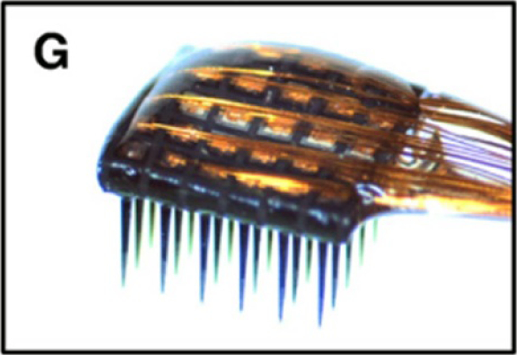
Photograph of the backside of a mounted Utah array containing 36 electrodes of 1 mm length. Reprinted from [10], Copyright (2009), with permission from Elsevier.
Unlike the other commonly used clinical arrays, the Utah array has a pneumatic insertion tool which inserts the device into the tissue at a high speed (8–10 m s−1 [10, 76], as compared to 50–400 μm s−1 for microwires [7, 9], 50–100 μm s−1 for carbon fibers [35], and <10 μm s−1 for multisite silicon probes [47]) after removing the dura above the implantation site. This has been shown to reduce tissue damage (as compared to slow insertion) in Utah arrays because each electrode can slice through the tissue, rather than dimpling and compressing it [43, 44].
2.5. Multisite silicon arrays
Multisite silicon arrays (figure 14) are planar probes built on a silicon backbone. Probe designs can vary widely, however, commonly reported features are multiple electrodes per shank ranging from 10 to 30 μm in diameter and an overall cross-sectional size of approximately 120–200 μm wide by 15–50 μm thick [10, 19, 21, 46–49] with either rectangular or ovular cross sections. At this thickness, the silicon probes can become slightly flexible, but are generally stiff enough to be directly inserted without buckling. The electrodes are usually sized for recording single unit signals [19]. Multisite silicon probes have been used in rodents, large mammals, and NHP, with no devices currently approved for human use [48, 49, 77]. The probes are slightly larger than microwires and can have several sharp edges, leading to a slightly increased immune response [46]. In addition, if arrays of probes are inserted together (as is often done to achieve high density recording—see figures 15 and 16), the immune response is greater due to the close proximity of multiple probes, but the signal to noise ratio remains relatively constant over time [10].
Figure 14.
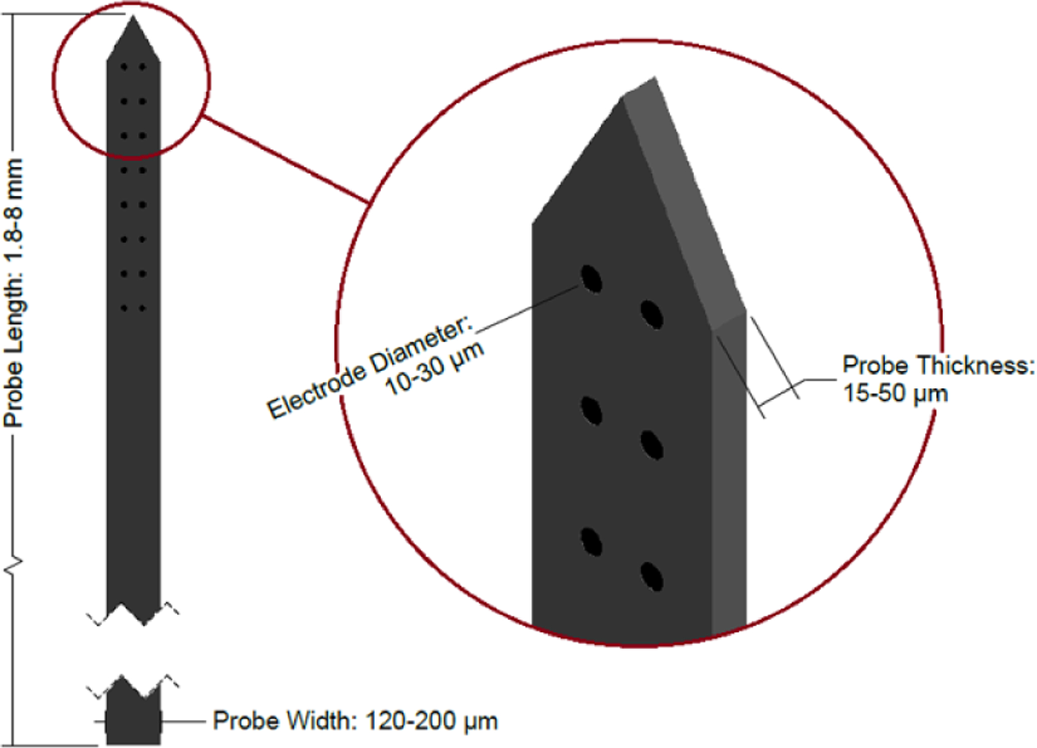
Diagram of a multisite silicon probe. Note that the tip shape and electrode arrangement vary between devices—the design shown here is one example. Dimensions sourced from [10, 19, 21, 46–49].
Figure 15.
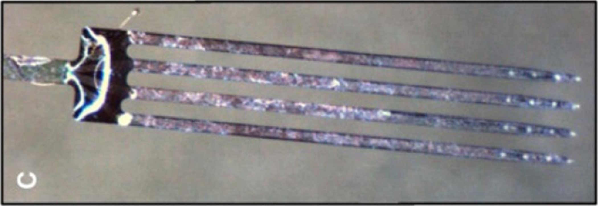
Photograph of a Neuronexus multisite silicon array with 16 electrodes (four shanks with four electrodes at the tip of each probe). Reprinted from [10], Copyright (2009), with permission from Elsevier.
Figure 16.
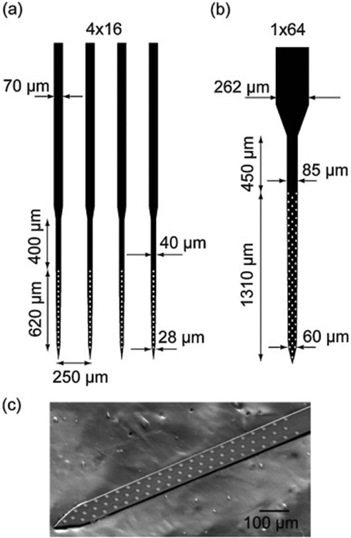
(A) Diagram of a multisite silicon array with four shanks with 16 electrodes each. (B) Diagram of a multisite silicon array with one shank with 64 electrodes. (C) SEM image of the distal end of the 1 × 64 probe. Reprinted from [47], Copyright (2012), with permission from Elsevier.
Multisite silicon devices can be inserted using a stereotactic stage with manual insertion. Alternately, devices can be manually inserted using forceps for less accurate placement. In most cases, the dura is incised or removed prior to insertion of the probe [49].
2.6. Neural dust
Neural dust is a recent development in the field of neural recording which consists of three parts: free-floating wireless sensor ‘motes’ which are implanted into and record from tissue, a subdural transceiver which communicates with the sensor motes, and a wireless receiver which receives data from the transceiver (see figure 17). The theoretical size of the sensor motes should be approximately 10–100 μm cubes [51, 52], however all published experimental devices are larger (0.8 × 1 × 3 mm, for example—see figure 18), with electrodes sized for single unit recording [53]. Because these devices are relatively new, they have only been implanted in the peripheral nerves of rodents thus far by incising the skin and manually placing the dust mote in contact with the nerve [53]. The planned insertion technique for the smaller, theoretical neural dust is via microsurgical techniques, such as injection through a needle [51].
Figure 17.
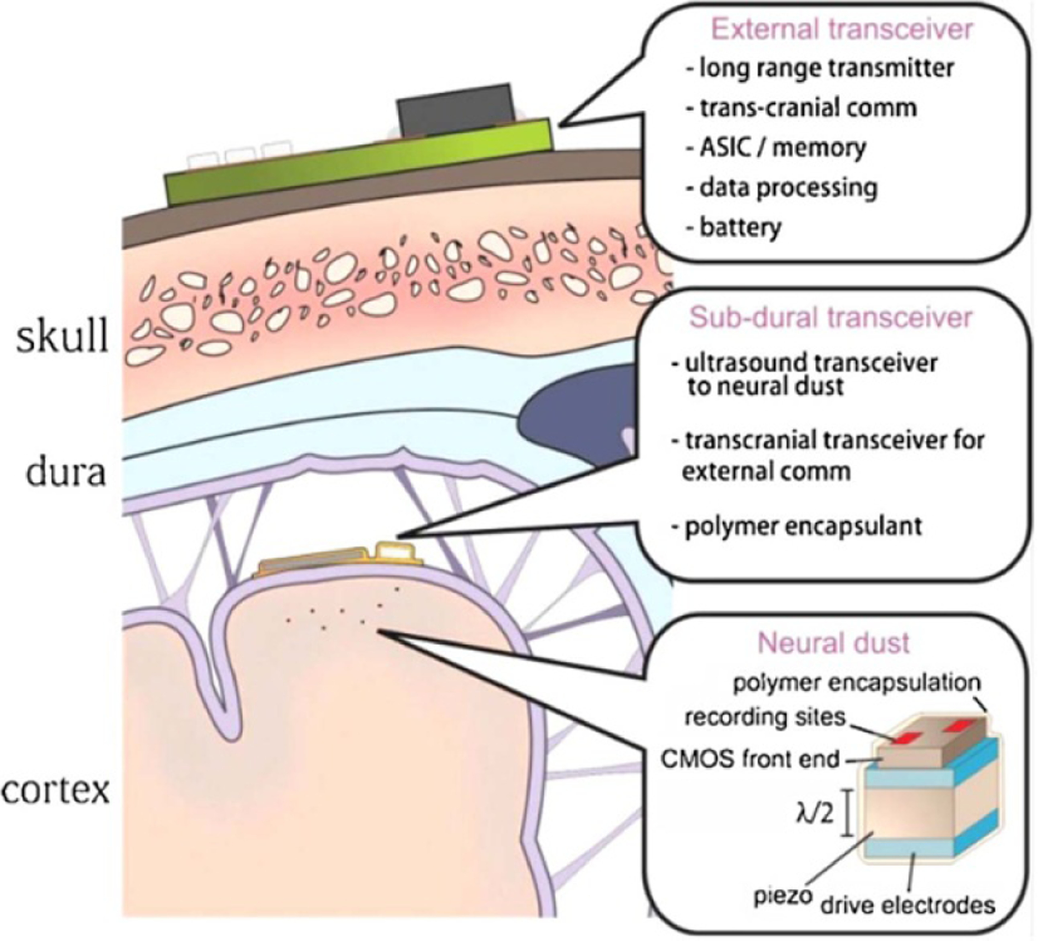
Diagram of a neural dust recording system. The external transceiver is placed on the scalp and communicates with the subdural transceiver, which is placed underneath the dura on the brain surface. The neural dust nodes are inserted into the brain tissue and communicate with the subdural transceiver. Reprinted from [51], Copyright (2015), with permission from Elsevier.
Figure 18.
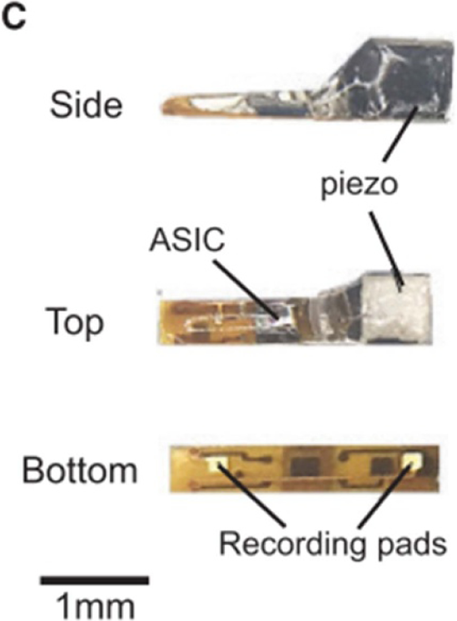
Photographs of a prototype neural dust mote. Reprinted from [53], Copyright (2016), with permission from Elsevier.
3. Tissue response
3.1. Acute response
As a probe is inserted into brain tissue, it causes damage to tissue along and adjacent to the insertion path, including capillaries, extracellular matrix, glial cells, and neurons, which triggers the body’s wound healing response. Erythrocytes, platelets, and clotting factors are released and the complement cascade is activated. This leads to the recruitment of macrophages to remove any excess fluid or debris and aims to rebuild the damaged tissue. At the same time, cytokines and neurotoxic free radicals are released in an attempt to degrade the probe. This collective immune activity creates a region of increased pressure and fluid build-up around the implant which persists for 6–8 d [23, 78]. The magnitude of this response is impacted by several aspects of the probe design, such as the size, shape, and whether or not it is tethered to the skull. In devices with larger probes, sharper edges (as are present in some planar silicon probes), and/or a rigid connection to the skull, the immune response is more severe [46, 79]. In addition, the immune response is generally more severe if inserting a probe into a region with large blood vessels (>5 μm diameter) as compared to a region without large vessels [80].
The overall magnitude of this acute immune response in turn impacts the magnitude of the chronic response [23]. As such, a smaller, less invasive insertion technique should lead to reduced acute and chronic inflammation. Additionally, studies have shown that, when probes are inserted and quickly removed (a stab wound), brain tissue will heal in the absence of a foreign body and the probe tracks are not visible via histology [23]. This suggests that the continued presence of an implant within the tissue has a significant impact on the resulting tissue response.
3.2. Chronic response
After the initial 6–8 d acute tissue response, chronic effects begin to take place. These are in part attributed to the large difference in mechanical properties between the probe and the brain tissue during normal brain movement (such as occurs during breathing, blood pumping, or walking) with an increased effect when the device is tethered to the skull [23, 49, 78]. The Young’s modulus (which describes the mechanical stiffness) of brain tissue and most probe materials differ by many orders of magnitude (see figure 19). The presence of a foreign body activates the body’s immune response, and the stiffness mismatch amplifies it, although the foreign body response can be mediated by using a probe with a small cross-section, which produces a more flexible probe (see equation (2)). Initially, activated microglia, which modulate the immune response, and astrocytes, which later form a glial scar, travel to the probe. When macrophages cannot degrade the probe (during the acute response), the astrocytes are recruited to wall off the implant and a glial scar forms around the probe. This glial sheath forms around 6–10 weeks after insertion and has a typical thickness of 50–100 μm. The formation of the glial sheath increases the distance between the probe and the target tissue, thus increasing the impedance of the electrode-tissue interface and leading to signal degradation [23, 78]. As is the case with the acute response, the chronic response is less severe when using a probe with a small cross-section or a small Young’s modulus (both producing a more flexible probe), a probe that is not rigidly attached to the skull, and/or a probe with soft (non-sharp) edges [46].
Figure 19.

Young’s modulus ranges of brain tissues, agarose, and common probe materials (see table 2 for specific material values).
In addition to the these acute and chronic responses, micromotion of the probe relative to the brain (millimeter-scale motion in the brain caused by things such as walking, breathing, and pulsing of blood in vessels) continuously aggravates the device-tissue interface, causing repeated injuries to the tissue and leading to a continuous immune response that may result in a thicker glial scar [100, 101]. The thickness of the glial scar resulting from this micromotion is directly related to the mass of the implant (larger mass yields a thicker scar) because heavier implants experience greater inertial forces during motion [102]. In addition, the glial scar is more severe when using materials that are much harder than brain tissue (materials with a higher Young’s modulus) [100, 101]. These studies indicate that a lighter, softer, and more flexible implant which more closely matches the mechanical properties of the tissue is preferable for mitigating the immune response and enabling long term use.
3.3. Evaluation of immune response
The foreign body response is primarily evaluated using in vivo implantation and subsequent histology. After fixation, the tissues are sliced and stained using standard histology dyes to observe cell morphology, population, types, and location with respect to the implant track. In some cases, immunohistochemistry is used as a type-specific cell staining technique to help observe the reaction to the foreign body [23]. One of the main limitations of histological evaluation is that often removal of the device, especially if it is constructed of stiff materials that cannot be sectioned, is required prior to slicing the tissue. This can lead to some shifting of the tissue and inaccurate information about the tissue response around the probe.
Other methods have been used to evaluate tissue response, such as two-photon microscopy which can image the cellular activity around an implanted probe in vivo and provide a better description of how the immune response progresses over time [63, 79, 80, 103]. In addition, two-photon microscopy can be used to plan probe insertions to avoid blood vessels and lessen the immune response during and after insertion [23, 80]. Confocal microscopy has been used to image both the cell volume around the probe during insertion [104, 105] and prepared histology samples [10, 79, 106–108] to provide information on the 3D cellular response around the inserted probe. A tissue processing method called CLARITY has been used to produce optically transparent tissue and allow for more detailed imaging, however this method causes expansion of the tissue, making it impossible to preserve the device/tissue interface [109].
4. Materials and form factor of flexible arrays
The rigid penetrating probes discussed thus far in this review are made of materials having Young’s moduli above approximately 50 GPa (e.g. silicon, platinum, carbon fiber, glass—see table 2 and figure 19). This is significantly higher than the modulus of human brain tissue (0.6–15.2 kPa for brain, 31.5–61.5 MPa for dura), which can contribute to the overall immune response [84–87, 102].
Table 2.
Young’s moduli of human and rat brain tissues, agarose brain phantom, flexible probe materials, and stiff probe materials.
| Material | Young’s modulus | |
|---|---|---|
| Brain tissues | Rat cortex [81] | 0.03–1.8 kPa |
| Rat hippocampus [81, 82] | 0.04–1.2 kPa | |
| Rat dura [83] | 0.4–1.2 MPa | |
| Human cortex [84, 85] | 0.6–15.2 kPa | |
| Human hippocampus [85] | 2.3–12.9 kPa | |
| Human dura [86, 87] | 31.5–61.5 MPa | |
| Brain phantom | Agarose, 0.5% [88] | 5.1–5.6 kPa |
| Flexible probe materials | PDMS [89] | 0.4–9.4 MPa |
| Polyimide [90, 91] | 1.0–8.5 GPa | |
| SU-8 [92] | 2.2–8.1 GPa | |
| BCB [93] | 2.7–3.1 GPa | |
| Parylene C [94] | 2.8 GPa | |
| LCP [95] | 9.3–31 GPa | |
| Stiff probe materials | Glass [96, 97] | 50–90 GPa |
| Silicon [97] | 62–202 GPa | |
| Platinum [98] | 154–172 GPa | |
| Carbon fiber [99] | 206–482 GPa |
In order to reduce the severity and size of the glial encapsulation and allow for long term recording, flexible probe materials (with moduli below approximately 10 GPa) are used. These flexible probes are realized using thin film fabrication techniques which allows for complex patterning of thin metal films on flexible substrates, resulting in a flexible device in the shape of a beam (length > width > thickness) that can support lateral and vertical bending as well as some torsional bending. The most commonly used substrate materials are parylene C (poly (chloro-p-xylylene)), polyimide, and polydimethylsiloxane (see table 2 and figure 19). Other flexible materials such as liquid crystal polymer (LCP), SU-8 photoresist, benzocyclobutene (BCB), and parylene HT (poly[(2,3,5,6-tetrafluoro-1,4-phenylene) (1,1,2,2-tetrafluoro-1,2-ethanediyl)]) have also been used, but remain less common.
The majority of flexible and rigid penetrating probes share a similar overall form factor of a rectangular cross section (1–30 μm thick by 10–554 μm wide) with a pointed tip on one end (for insertion into tissue) and an interface with recording or stimulation electronics on the other end. Probe lengths range from 0.7 to 15 mm, and electrode sizes range from 10 to 55 μm in diameter [54, 55, 57–63]. Typical dimensions of flexible probes compared to rigid clinical and research probes is summarized in table 1. There are some alternate probe geometries which are used less frequently, such as neural threads and meshes. These devices generally have a smaller cross section (such as 0.5 μm thick by 5–20 μm wide [110, 111]) and are constructed in single threads or cross-hatched meshes.
5. Implantation of flexible probes
Similar to most other probe types, the implantation of flexible probes begins with the removal of the skull above the insertion site (by creating a burr hole or a craniotomy). In most cases, the dura is incised or removed prior to inserting the probe [8, 35, 44, 49, 54, 57, 59, 106, 112–122], however some insertion techniques allow insertion of a probe through the dura [9, 60, 79, 123–126]. Some probes also require the removal of the pia if the buckling force of the probe is sufficiently small [55, 79, 112, 127–129], especially in larger animal models (which generally have thicker and stiffer pia than smaller animals) [130]. Most polymer probes cannot be inserted without additional mechanical reinforcement of some kind because they are too flexible and will buckle before they penetrate the brain tissue. Once the probe is inserted within the brain, it must travel to the targeted region. Accurate insertion of longer, thinner, and narrower probes can be challenging. The majority of flexible probes have been developed for use in small animal models and the insertion depth rarely exceeds 5 mm. Longer flexible probes suitable for accessing deeper brain regions or for use in larger animals can only be successful if they are accompanied by methods or tools to achieve accurate implantation. The mechanics governing insertion are examined below, followed by a discussion of different methods to achieve implantation of flexible probes.
The success of the initial insertion of the probe into the brain is governed by the buckling equation (1) which captures the axial stiffness of the probe and the geometric shape to calculate the required force to insert the probe into the tissue. As a probe is inserted, the insertion force must be greater than the puncture force of the brain tissue (or the dura, if it is not incised or removed) in order for the probe to puncture the tissue (figure 20(A)). If the insertion force is less than the buckling force, the probe will successfully insert (figure 20(B)). Conversely, if the insertion force is greater than the buckling force, the probe will buckle and will not insert into the tissue (figure 20(C))
| (1) |
where E = Young’s modulus, I = second moment of area, L = unsupported length, K = length factor.
Figure 20.
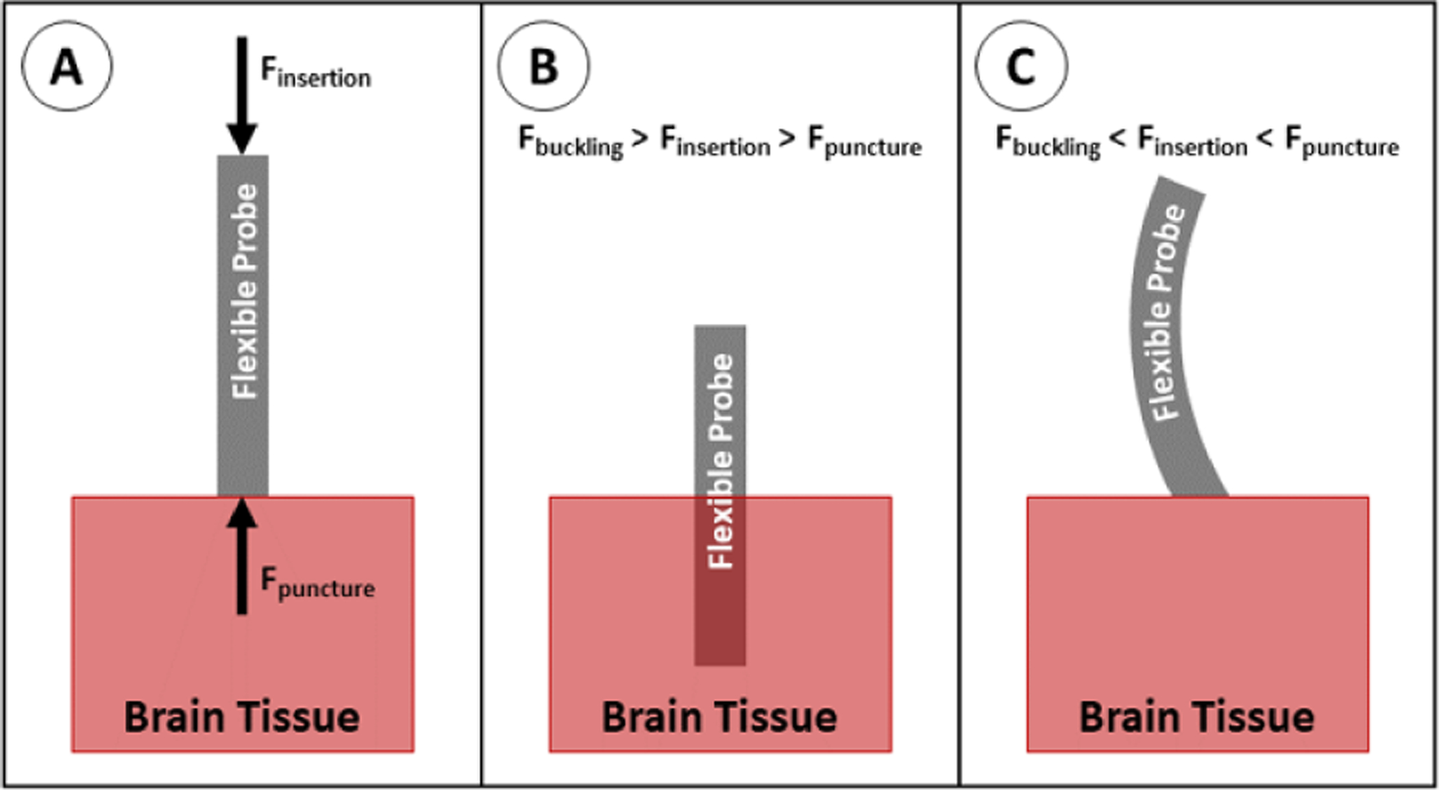
Insertion of a flexible probe into brain tissue. (A) Insertion force acts on the proximal end of the probe; puncture force acts on the distal tip of the probe. For successful insertion, the insertion force must be increased until it is greater than the puncture force. (B) If the insertion force is less than the buckling force, the probe overcomes the puncture force and inserts into the tissue. (C) If insertion force is greater than the buckling force, the probe buckles before the insertion force can overcome the puncture force.
Each component of the buckling equation can be altered by changing the insertion method or probe properties.
The Young’s modulus, E, can be increased by choosing a stiffer probe material (see table 2 for the moduli of commonly used materials). In practice, this can be achieved by laminating a stiffer shuttle to the probe or coating the probe in a stiffer material for surgical implantation.
The second moment of area, I, depends on the cross-sectional area and shape of the probe. As described in equation (2), the second moment of area is a measure of the distance (r) between each portion of the cross section (dA) and a reference axis (in this case, the axis about which the probe bends). This value can be increased by increasing the cross-sectional area of the probe (increasing the value of A in equation (2)) or by changing the shape of the cross section to move material farther away from the bending axis (increasing the value of r in equation (2)). This can also be increased by laminating a removable shuttle to the probe or coating the probe in a dissolvable material
| (2) |
The length factor, K, depends on the support at the proximal and distal ends of the probe. Each end can either be ‘fixed’ (unable to translate laterally or rotate), ‘hinged’ (cannot translate laterally, but can rotate about a single point), or ‘free’ (able to translate laterally and rotate). For probe insertions, the proximal end is always fixed because it is being held by the insertion equipment. For the distal end, fixed, hinged, and free states correspond to K values of 0.5, 0.707, and 2.0 respectively. In most cases, the proximal tip is assumed to be hinged (able to rotate, but unable to move laterally) [9, 59, 112, 122, 130, 131], however some studies assume the tip is able to puncture the tissue and become fixed (unable to rotate or move laterally) [121].
The length, L, corresponds to the unsupported length of the probe, which can be decreased by adding supports along the length of the probe during insertion.
The force necessary to puncture and pass through the brain tissue (depicted as Fpuncture in figure 20) is dependent on the properties of the tissue, the cross-sectional area of the probe (larger probes must displace more tissue, requiring a larger force; see equation (3)), and the sharpness of the probe (sharper probes can cut through tissue more easily than dull probes). The required force per area (or stress) is studied in two different phases: puncture stress and end stress
| (3) |
Puncture stress describes the amount of force per area required to penetrate the surface of the tissue. In many cases, the tips of probes will be pointed or sharpened in order to decrease the cross-sectional area at the tip and thus decrease the puncture force. End stress describes the amount of force per area required to overcome frictional drag while the probe inserts deeper into the tissue, breaking through new tissue in the process. Tip sharpness has been shown to decrease the puncture force of the probe through the pia mater, but has no effect on the end force [132]. The puncture stress of brain tissue ranges from 20 to 120 kPa and maximum end stress ranges from 40 to 200 kPa in mouse and rat models [113, 119, 127]. These values vary with insertion speed (lower speeds tend to have lower end stresses), however many studies have some results which do not follow this general trend, indicating that there is a large variation between individual animals and species [119, 127].
Flexible probe solutions must balance the competing requirements of the need for flexible materials and small footprint to reduce immune response and buckling and insertion physics for accurate placement without probe failure.
6. Insertion techniques
Several insertion techniques have been developed for implanting flexible probes. The most commonly cited techniques are discussed in this section. Each of these techniques begins with the removal of the skull (via burr hole or craniotomy) and, unless otherwise specified, the incision/removal of the dura above the insertion site.
Most of the techniques discussed in this section have been optimized for the insertion of a single probe. However, when larger brain regions are studied, probe arrays are necessary to collect data throughout a larger volume of brain tissue. Limited data is available on the buckling and insertion success of arrays having closely spaced probes. This section focuses on insertion of single probe arrays, but some discussion of scalability to multiple probes is included.
6.1. Unaided insertion
The simplest insertion method is to insert the array as is (figure 21). This is either done by hand, using a pneumatic inserter, or using a stereotactic stage. This method works well for short probes, thick/wide probes, or probes made of stiffer materials. Referring back to the buckling equation, these properties correspond to smaller L, larger I, and larger E. This method generally requires the removal or incision of the dura prior to inserting the probe, however the dura can remain intact prior to insertion if using a sufficiently stiff or large probe [7, 125]. This is the method widely used for rigid probes, such as microwires [7, 8], large cross section or very short (<1 mm long) flexible probes [125, 133–136], and arrays of probes as long as each probe is sufficiently large, short, and/or rigid to prevent buckling. As a result, this method can only be used with flexible probes when inserting into shallow brain areas (several mm into the cortex), and may have poor targeting accuracy due to the lack of support on the probe as it is inserted. As smaller, longer, and more flexible devices are developed, other techniques are required to prevent buckling.
Figure 21.
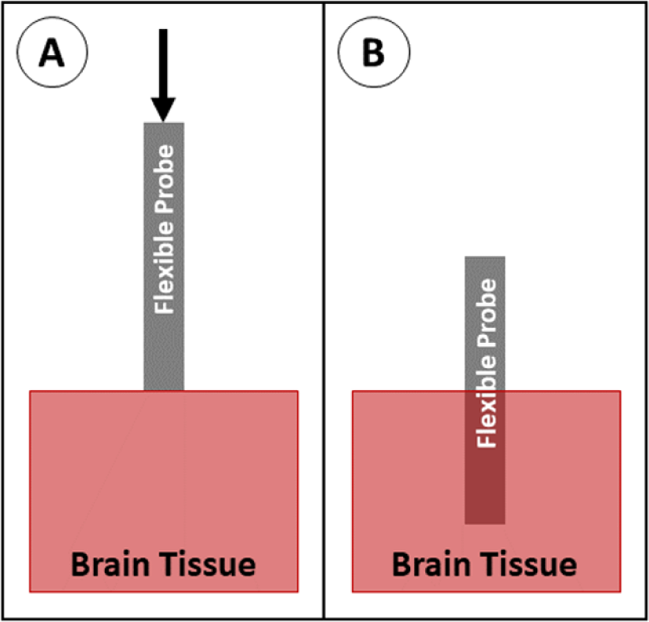
Insertion of a probe with no aid. (A) The probe is positioned above the brain tissue and advanced downward. (B) The probe is fully implanted.
6.2. Shuttle
A rigid insertion shuttle can be temporarily attached to the back side of the probe which increases probe dimensions and stiffness to enable insertion. Insertion can be accomplished with or without the incision/removal of the dura, depending on the dimensions of the shuttle. After insertion, the shuttle is removed, leaving the probe in place (figure 22). Most commonly, these shuttles are made of micromachined silicon, although metal microwires are also widely used. The use of an insertion shuttle effectively increases the stiffness and the cross-sectional area of the probe during insertion. These properties correspond to increased E and I in the buckling equation. Numerous groups have evaluated the use of silicon shuttles [118, 120, 130, 137–139] and metal rods as insertion shuttles [55, 100, 140–143], and many groups default to this technique for implantation of neural probes because it is relatively simple to implement and is well known to be successful. This method is often the preferred insertion technique for deep brain probe insertion because of the increased stiffness when using longer probes, the relatively small cross section of the shuttle/probe assembly (as compared to using a dissolvable stiffener), and the potential for greater targeting accuracy (as compared to insertion methods which do not support the probe as it passes through the tissue). In addition, the shuttle technique can easily be scaled up to allow insertion of multiple probes simultaneously [120, 138–140]. When inserting one or multiple probes, however, care must be taken to reliably separate the probe from the shuttle after implantation to prevent retraction of the probe as the shuttle is removed.
Figure 22.
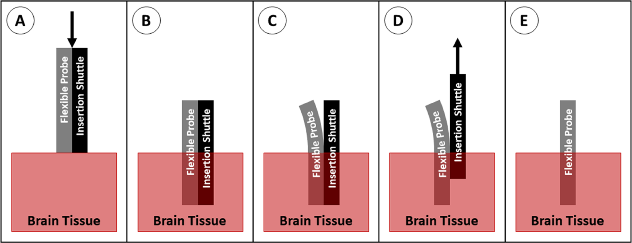
Insertion of a probe with a shuttle. (A) The probe and shuttle are positioned above the brain tissue and advanced downward. (B) The probe and shuttle are in place. (C) The probe is peeled away from the shuttle, usually using saline to separate them. (D) The shuttle is retracted out of the tissue, while the probe is held in place. (E) The probe retained in the brain.
6.3. Dissolvable stiffener
A dissolvable material can be used to coat one or all sides of the entire length of the probe or to fill a channel within the probe. Once the probe is in place, the stiffening material is dissolved and resorbed into the brain tissue, leaving the flexible probe behind (figure 23). Although not all stiffeners have a higher modulus than the probe material (see table 3), the stiff coating or filled channel increases the cross section, corresponding to a larger I value in the buckling equation. Many groups have tried different combinations of stiffeners and probe materials, with the most common stiffeners being polyethylene glycol (PEG) [58, 121, 144–146], silk [62, 112, 121, 147, 148], and various sugars [60, 61, 149–151]. Other materials have been used when unique properties are required, such as carboxymethylcellulose (CMC) [79, 126] and tyrosine-derived polymer [59, 106] which quickly soften to gels, then resorb after prolonged implantation in the body. This method is generally used for probes less than 6 or 7 mm in length [121]. At this length, the probe can be sufficiently stiffened to reach its target without a prohibitively thick coating that causes damage to surrounding tissue. The dissolvable stiffener method can be used to implant multiple probes simultaneously, however, if a coating is added to all sides of the probe, the individual probe shanks must be sufficiently far apart from each other to allow individual coating of each probe with the stiffener [58, 79, 126, 146] or the probe design must account for the clumping of individual probes during coating and insertion [126, 145, 152].
Figure 23.
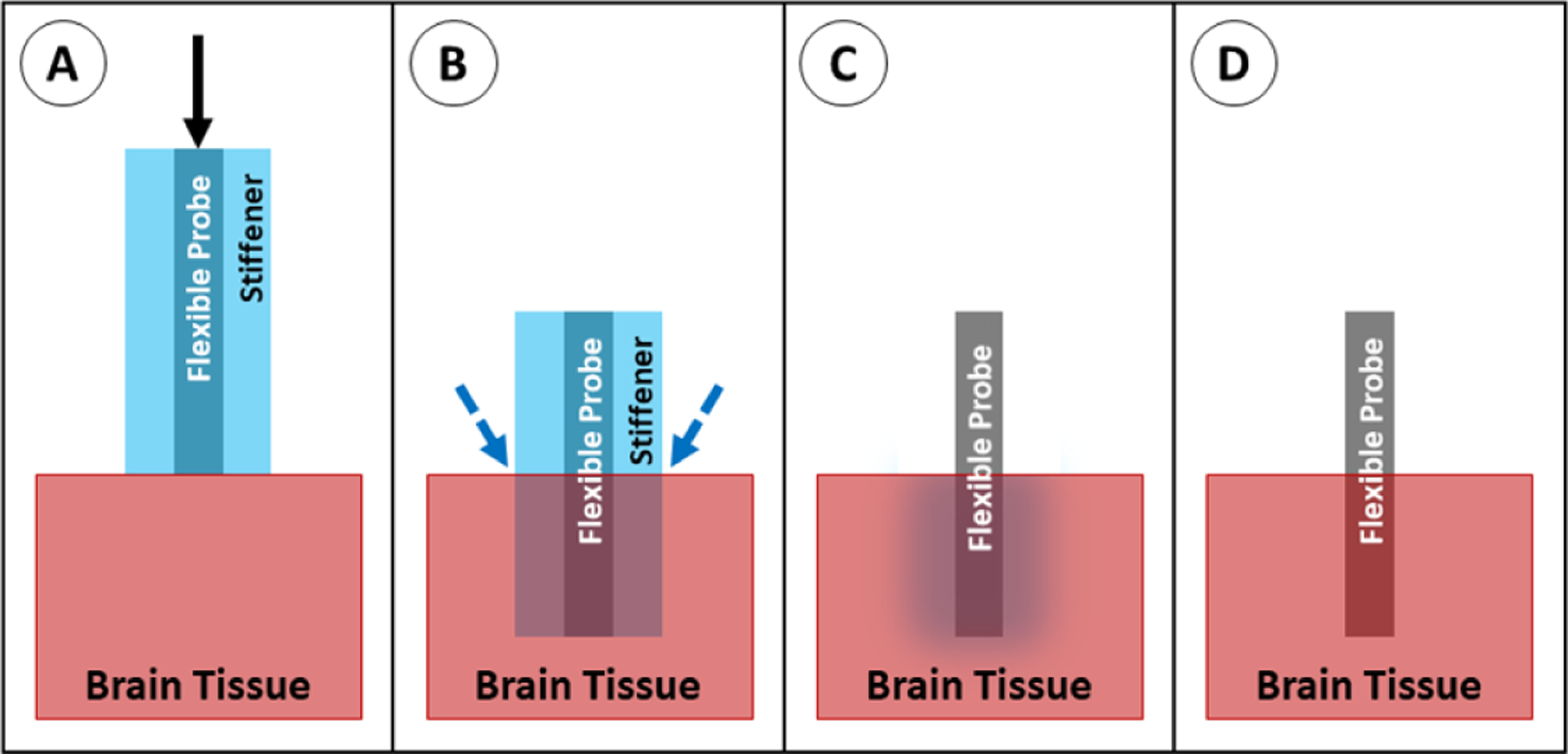
Insertion of a probe with a dissolvable stiffener. (A) The stiffened probe is positioned above the brain tissue and advanced downward. (B) The probe is in place; saline is applied to dissolve the stiffener. (C) The stiffener dissolves. (D) The probe is fully implanted.
Table 3.
Young’s moduli of common dissolvable stiffeners.
6.4. Surface guide
A rigid guide can be placed on the surface of the brain to support the probe from all sides during insertion and is removed after implantation (figure 24). The placement of this support at the tip of the probe in the region directly adjacent to the brain acts to support the probe’s distal end and shortens its effective length (the free length is prone to buckling), corresponding to smaller K and L values in the buckling equation. This method has not been widely studied, however a few groups have reported successful implantations using a guide in combination with actuation of the probe, with and without the removal/incision of the dura [9, 124]. This method is effective in limiting buckling while maintaining the original cross-sectional area of the probe, however the method may not scale well for use in placement of arrays of probes because of the large size of the guide on the brain surface. In addition, this method suffers from relatively poor targeting accuracy due to lack of probe support as the probe passes through the tissue.
Figure 24.
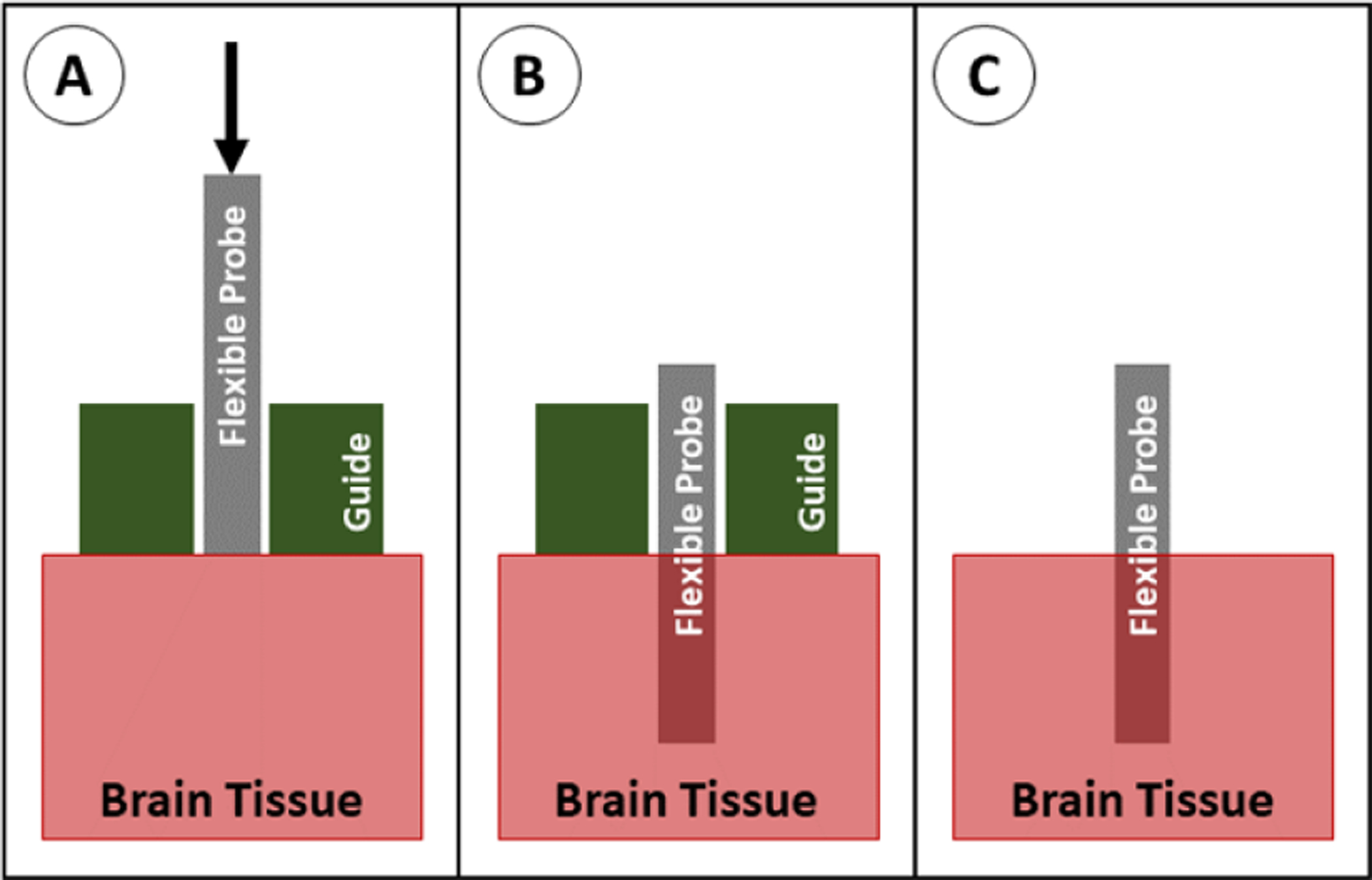
Insertion of a probe with a guide. (A) The probe is positioned above the brain tissue with the guide sitting on the brain, and the probe is advanced downward. (B) The probe is in place, and the guide is removed. (C) The probe is fully implanted.
6.5. Dissolvable brace
To support the probe during insertion, a dissolvable brace, most commonly made of silk [155] or PEG [34, 35, 54], can be molded around the probe, leaving only the tips exposed. The brace holds the proximal end of the probe in place as the probe tip inserts into the tissue, then the brace can be melted away from the distal end, exposing more of the probe length for insertion (figure 25). This method shortens the effective length of the probe to the exposed (non-braced) length, effectively decreasing the value of L in the buckling equation. This method is somewhat rare in the literature, but has been successfully used for in vivo implantation of carbon fiber [35] and parylene [54, 156] probes. This method prevents buckling and maintains the original probe cross-sectional area, but has relatively poor targeting accuracy because the probe is unsupported as it travels through the tissue. In addition, the method requires additional steps to add the brace during fabrication and to dissolve it during implantation.
Figure 25.

Insertion of a probe with a dissolvable brace. (A) The braced probe is positioned above the brain tissue and advanced downward. (B) Once the brace reaches the tissue, saline is applied at the brain/brace interface. (C) The bottom of the brace dissolves. (D) The probe is advanced again, and the dissolving/advancing steps are repeated until the target depth is reached. (E) Once the probe reaches the target depth, saline is applied to dissolve the remainder of the brace material. (F) The probe is fully implanted.
6.6. Stiff tipped
Rather than using a flexible polymer for the full length of the probe, a rigid tip (usually made of silicon) can be added to the end of the probe. The stiff tip makes it easier for the probe to penetrate into the tissue and decreases the length of the flexible cable, which is more susceptible to buckling (figure 26). This is effectively modeled as two beams in series, one of which has a larger E, and both of which have a smaller L in the buckling equation. Unlike other methods, these probes feature hybrid construction and contain a permanently stiff region that is chronically implanted in the tissue [157]. As with unaided insertion, the stiff-tipped insertion can easily be scaled to allow insertion of multiple probes simultaneously as long as the probes are sufficiently large, short, or stiff, and as such it can only be used when inserting probes into shallow brain areas (several mm into the cortex), and may have poor targeting accuracy.
Figure 26.
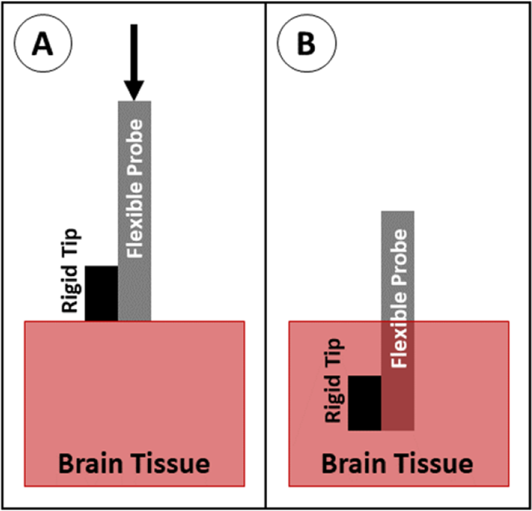
Insertion of a probe with a stiff tip. (A) The probe is positioned above the brain tissue and advanced downward. (B) The probe is fully implanted.
6.7. Stiffness changing coating or backbone
The stiffness of the probe can be temporarily increased to aid with insertion by using a stiffness-changing structure or material as a part of or as the entire probe backbone. This can be done in several ways: by adding a microfluidic channel to a polymer probe and filling the channel with a stiffness-changing material, such as pressurized and frozen gallium [158] or pressurized water [159], by coating a polymer probe with a stiffness-changing material, such as a shape memory polymer (see figure 27) [115, 160–163], or by building the probe itself out of a stiffness-changing material such as poly(vinyl acetate) nanocomposite (PVAc) [129, 131, 164, 165] or off-stoichiometry thiol-ene-epoxy (OSTE+) [166]. In each of these cases, the material is in a stiff state prior to and during implantation, then changes to a flexible state after warming up to body temperature or saturating with saline/water (see table 4 for the Young’s modulus of common materials and their mechanism of softening). Each of these scenarios correspond to a larger E and, in some cases, larger I in the buckling equation. This method can easily be scaled to allow insertion of multiple probes simultaneously. It is important to note, however, that the Young’s modulus of commonly used stiffness changing materials in the stiff state is still relatively low (comparable to other flexible materials used for probe construction—see table 2), so buckling is primarily prevented by increasing the cross-sectional area. As such, this method has similar targeting accuracy to probes inserted without an aid or with a dissolvable stiffener, and is only applicable to relatively short (less than 9 or 10 mm) probes.
Figure 27.
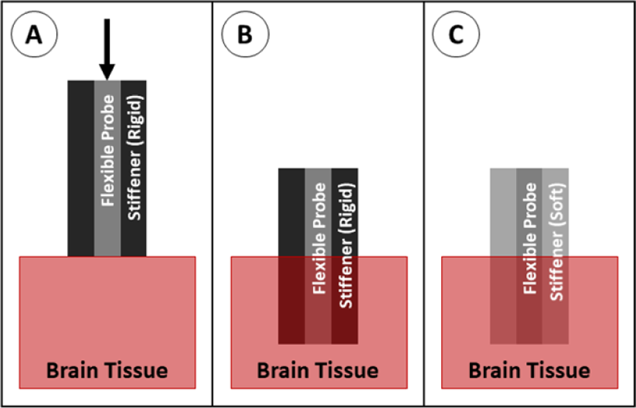
Insertion of a probe with a stiffness-changing coating. (A) The probe with stiffener is positioned above the brain tissue and advanced downward. (B) The probe is in place and begins to warm to body temperature or absorb fluid, softening the stiffener. (C) The probe is fully implanted.
Table 4.
Young’s moduli of common stiffness changing materials.
| Material | Softening mechanism | Young’s modulus (stiff) | Young’s modulus (soft) |
|---|---|---|---|
| Frozen/pressurized gallium [158] | Solid to liquid transition at ~37 °C Pressure dropped from 414 to 0 kPa | 10 GPa | N/a (liquid) |
| Pressurized water [159] | Pressure dropped from 60 to 0 kPa | N/a (liquid) | N/a (liquid) |
| Shape memory polymer [59, 160–163] | Saturation with saline at 37 °C | 0.7–2 GPa | 0.3–300 MPa |
| Poly(vinyl acetate) nanocomposite (PVAc) [129, 131, 163, 164] | Saturation with saline at 37 °C | 4–5 GPa | 10–12 MPa |
| Off-stoichiometry thiol-ene-epoxy (OSTE+) [166]. | Heating to 37 °C | 1.9 GPa | 50 MPa |
6.8. Engineered cross section
The shape of the probe cross section can be modified such that the probe cannot buckle as easily as it is being inserted. The modification of the cross section increases the second moment of area (I) in the buckling equation. This can be accomplished in several ways, including rolling the polymer probe into an arc shape [114, 167] or by adding polymer ‘struts’ perpendicular to the plane of the probe (figure 28) [128]. In some cases, the modified cross section reduces the flexibility of the probe. This method can be scaled to insert multiple probes simultaneously, however this would require very accurate alignment of the probes to prevent any twisting motion (which can lead to buckling). This method has not yet been widely studied, so it is difficult to discern the targeting accuracy as compared to other insertion methods and it is not used regularly for any particular type of probe or study.
Figure 28.
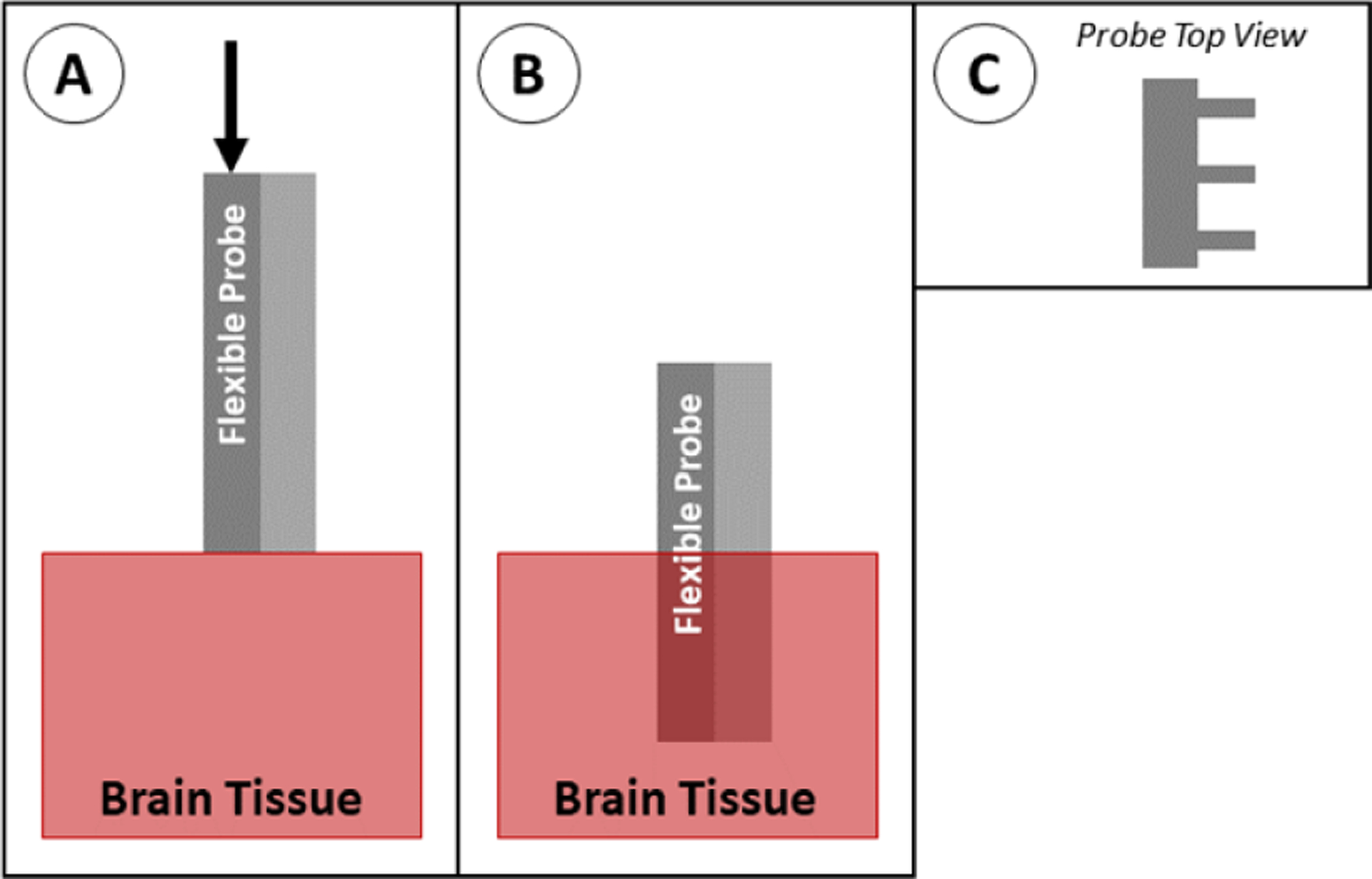
Insertion of a probe with engineered cross section. (A) The probe is positioned above the brain tissue and advanced downward. (B) The probe is fully implanted. The type of modified cross section shown here (C) has struts along the back of the probe for stability.
6.9. Magnetically guided
A probe can be steered into place using an external magnetic field if a small piece of magnetic material is attached to the tip of the shank (figure 29). In this system, the probe is no longer governed by the buckling equation because the force from the magnetic field is acting on the tip of the probe. In the in vivo applications of this method, the magnetic tip is fully encapsulated with a biocompatible material (such as parylene or polyimide) to prevent an immune reaction to the magnetic material (usually iron—which is toxic to the body) [123, 168, 169]. In recent studies, this has achieved good targeting accuracy of less than 1 mm [169]. Although this method is not currently widely used, it has great potential for applications in which accurate targeting is required. However, as is the case with the stiff-tipped method, magnetically guided probe tips contain a permanently stiff region at the tip that is chronically implanted in the tissue. This method can be scaled to implant multiple probes simultaneously if a sufficiently large magnetic field is used [168].
Figure 29.
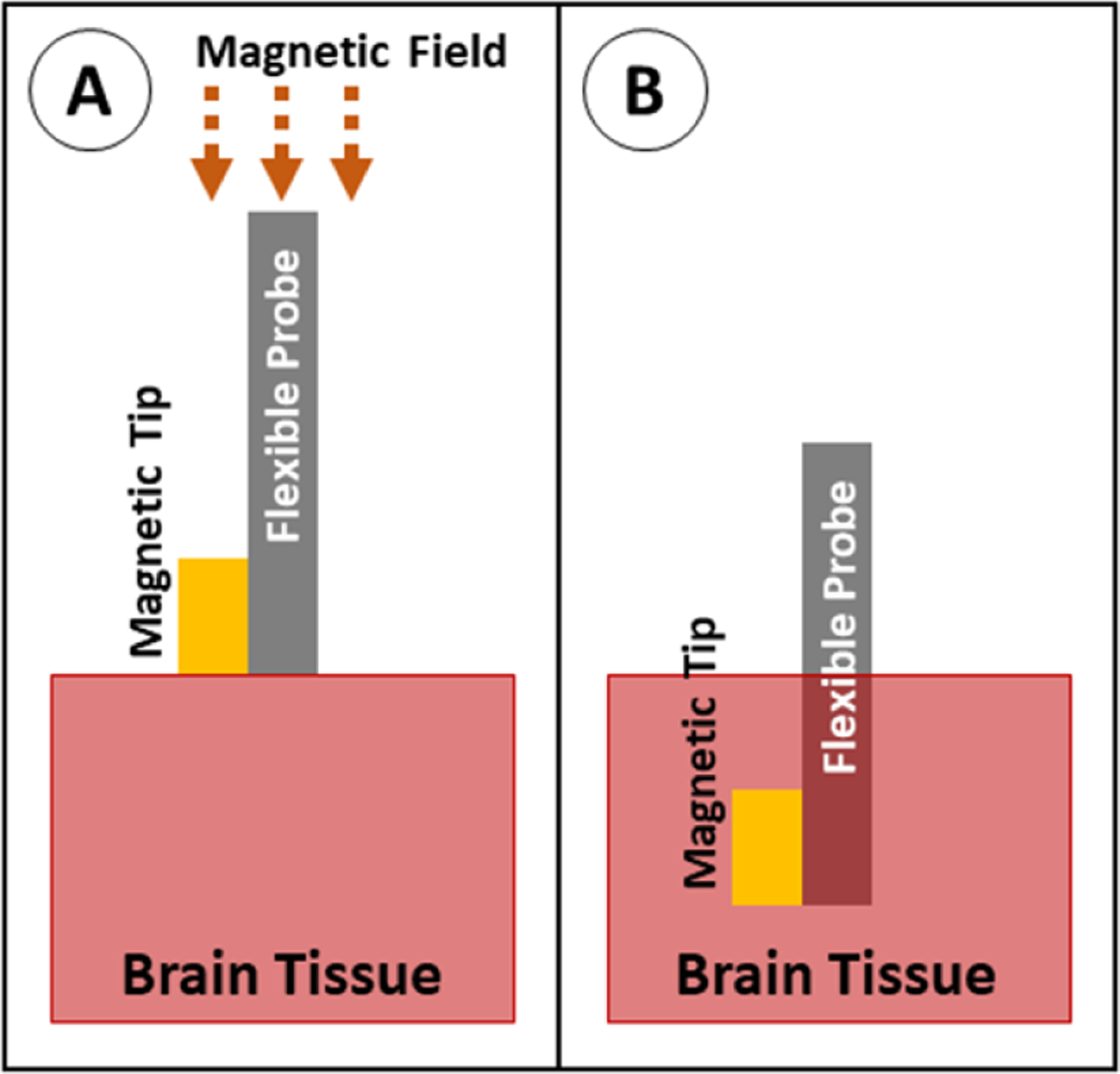
Insertion of a probe with magnetic guidance. (A) The probe with magnetic tip is positioned above the brain tissue, and a magnetic field is applied to force the tip downward. (B) The probe is fully implanted.
6.10. Injection
The probe can be inserted into a needle or cannula (suspended in saline), then injected into the relevant part of the brain. After the needle is inserted, the saline and probe are injected while the needle is withdrawn so that the device stays stationary in the target area (figure 30). The use of a needle means the device itself is no longer governed by the buckling equation, but rather the needle must be sufficiently strong to not buckle. This is accomplished either using stainless steel or glass needles ranging in size from 22 to 27 gauge (0.4–0.7 mm outer diameter). Because this method utilizes standard stereotaxic guidance, it can achieve similar targeting accuracy to SEEG or DBS probes (1.6–5.0 mm on average [5, 66, 67]). This method is used by a few groups, primarily for delicate, thread-like devices [170] or mesh devices [110, 111, 171, 172] which would not work well with other insertion methods.
Figure 30.
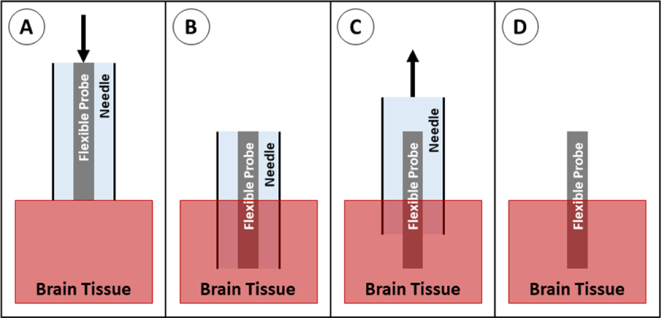
Insertion of a probe using injection. (A) The probe is suspended in a needle in saline, positioned above the brain tissue, and advanced downward. (B) The probe and needle are in place. (C) The needle is retracted at the same rate that fluid is pushed out of the needle, leaving the probe behind. (D) The probe is fully implanted.
7. Comparison of insertion methods
It is difficult to compare different insertion techniques from the current literature because of the wide variation in probe materials and geometries. In addition, evaluation methodologies differ greatly and specific materials in use are sourced from different suppliers and have widely varying properties. Each technique is typically reported by distinct groups of researchers and very limited comparison between methods has been reported. As a result, a comprehensive quantitative comparison between different insertion methods is not currently possible. Instead, qualitative comparisons are drawn between each of the methods relative to the insertion and buckling forces, surgical implantation difficulty, accuracy of probe targeting, the immune response of the tissue, and overall limitations (summarized in table 7). Where data are available, quantitative evaluations of each insertion method are given.
Table 7.
Comparison of insertion methods.
| Methoda | Surgical difficulty | Alignment and targeting | Tissue response | Limitations |
|---|---|---|---|---|
| No aid [7, 8, 125, 133–136] | Very easy | Inaccurate: Probe can easily be deviated by anatomical features | Minimal: Only due to probe size/material | Only works with short, stiff, and/or large cross section probes |
| Shuttle | Moderate: Requires some skill to separate probe from shuttle | Very accurate: Stiff shuttle unlikely to be bent/flexed during insertion | Moderate to high: Shuttle increases cross section, which increases trauma | Probe may shift as shuttle retracts |
| SS rod: [100, 142, 143] | ||||
| W rod: [55, 140, 141, 178, 179] | ||||
| Si plate: [118, 120, 130, 137–139, 180, 181] | ||||
| Diamond plate: [56] | ||||
| Dissolvable stiffener | Very easy to moderate: Stiffener may be brittle and require delicate handling | Semi-accurate: Probe can be deviated by anatomical features as stiffener dissolves during insertion | Moderate to high: Stiffener increases cross section, which increases trauma | Cannot retract and re-insert array if positioning is incorrect |
| PEG: [58, 121, 144–146] | ||||
| PEG/silk: [121] | ||||
| PEG/gelatin: [116] | ||||
| Silk: [62, 112, 121, 147, 148] | ||||
| Sugars: [60, 61, 149–151] | ||||
| CMC: [79, 126] | ||||
| TDP: [59, 106] | ||||
| Guide [9, 124] | Moderate to hard: Requires precise alignment of probe and guide | Inaccurate: Material can easily be deviated by anatomical features | Minimal: Only due to probe size/material | Only works with relatively short, stiff, and/or large cross section probes |
| Dissolvable brace | Easy to moderate: Dissolving brace requires close monitoring | Inaccurate: Material can easily be deviated by anatomical features | Minimal: Only due to probe size/material | Cannot retract and re-insert array if positioning is incorrect |
| PEG: [35, 54, 156] | ||||
| Silk: [155] | ||||
| Stiff tipped [157] | Very easy | Semi-accurate: The flexible shank can deviate during insertion | Moderate: Only due to probe size/material, but probe tip (where recordings occur) is a stiff material | Only works with relatively short, stiff, and/or large cross section probes |
| Stiffness changing material | Very easy to moderate: Can require removal of stiffener | Semi-accurate: Probe can be deviated by anatomical features as it warms and softens during insertion | Minimal: Only due to probe size/material | Current published materials are relatively soft—short and/or large cross section probes are required |
| SMP coating: [115, 160–163] | ||||
| PVAc backbone: [129, 131, 164, 165] | ||||
| Pressurized Gallium: [158] | ||||
| Pressurized Water: [159] | ||||
| Engineered cross section | Very easy | Semi-accurate: Probe can be slightly deviated by anatomical features | Minimal to moderate: May maintain stiffness after insertion | Fabrication can be prohibitively difficult |
| Rolled: [114, 167] | ||||
| Vertical Struts: [128] | ||||
| Magnetically guided [123, 168, 169] | Moderate to hard: Requires dedicated equipment and planning | Very accurate: Probe unlikely to deviate from planned path due to stiff tip and high speed insertion | Moderate: Only due to probe size/material, but probe tip (where recordings occur) is a stiff material | Most magnetic materials are not approved for long term implantation |
| Injection [110, 111, 170–172] | Easy to moderate: Requires simultaneous injection and retraction of needle | Accurate: Needle can be accurately placed, but small deviations may occur during needle retraction | High: Needle is generally large and stiff, causing increased trauma | Only works for devices with no bulky parts which can be fully inserted through a needle |
BCB = benzocyclobutene, CF = carbon fiber, CMC = carboxymethylcellulose, Ga = gallium, LCP = liquid crystal polymer, Pa = parylene, PE = polyethylene, PEG = polyethylene glycol, PI = polyimide, Pt = platinum, PVAc = polyvinyl acetate nanocomposite, Si = silicon, SMP = shape memory polymer, SS = stainless steel, TDP = tyrosine-derived polymer, W = tungsten.
7.1. Insertion medium
Insertion methods have been tested in various media. The most reliable insertion medium is live brain tissue, however other materials are commonly used to mimic the mechanical properties of the brain (otherwise known as brain phantom) so that live animals are not needed. The most common material used is 0.5%–0.6% agarose gel (because of its historical use and relatively low price), however other gels and emulsions have been evaluated more recently, some of which are better approximations of brain tissue [173, 174].
Thus far, no brain phantom is able to perfectly model brain tissue under all conditions. One major difference is the absence of the dura and pia in brain phantom; materials have been optimized to mimic certain properties of brain tissue, but the dura and pia are not included in most cases. Another major difference is the performance of brain tissue and phantom at varying insertion speeds. For example, in brain tissue, the maximum force during insertion tends to increase as insertion speed increases. In 0.6% agarose hydrogel, there is no significant change in maximum insertion force as insertion speed increases [119]. Some groups have reported better insertion rate dependence for two composite hydrogels (6% polyvinyl alcohol/0.85% phytagel in water, and 3% gelatin/1% agarose in water) and an oil-based emulsion (containing flax oil and soybean lecithin emulsified with water, gelatin, and borax) [174].
7.2. Insertion and buckling force
The insertion force and/or buckling force of the probe are straightforward to determine [57, 60, 62, 80, 85, 87, 101, 111, 113, 125, 148, 158]. These are measured by attaching the probe to a load cell and measuring the force as the probe is advanced downward into the brain tissue or phantom or into a hard surface until the probe buckles, respectively. The resulting force curve shows several properties, such as the force required to penetrate the tissue and the maximum force during insertion, or the maximum force on the probe prior to buckling. These provide information on the mechanical properties of the probe and an early indication of whether successful insertion into brain tissue can be achieved with a particular design.
In some studies, the repeatability of the insertion method is reported via the insertion success rate (number of successful insertions/number of attempted insertions) [46, 58, 122, 126], however this metric is rare in the published literature—most studies do not discuss failed insertions.
The wide variety of probe materials and geometries prohibits meaningful direct comparison of insertion methods used in different studies. When possible, some studies will compare the buckling or insertion force for a given insertion method to the force for unaided insertion, allowing some comparison between methods. A summary of several characteristic studies is shown in table 5. The data presented is the increase in buckling force between aided insertion (using an insertion technique) and unaided insertion (using a bare probe).
Table 5.
Summary of maximum buckling force increase between aided and unaided insertion for each insertion technique.
| Insertion technique | Material(s) | Buckling force increasea |
|---|---|---|
| Dissolvable stiffener [112, 121] | Parylene C (probe) 250 μm PEG (coatingb) | 18 |
| Parylene C (probe) 250 μm silk (coatingb) | 115 | |
| Polyimide (probe) 18–69 μm silk (coatingb) | 64–2498 | |
| Surface guide [124] | Polyethylene (probe) PMMA (guide) |
3.8–4.5 |
| Dissolvable brace [54] | Parylene C (probe) PEG (brace) |
3.5 |
| Engineered cross section [128] | Parylene (probe with struts) | 2.5–6.8 |
Force increase is defined as (force with insertion aid)/(unaided force).
Thickness refers to coating thickness, not full device thickness.
Although direct comparisons between the discussed insertion methods are not widely available, the comparison to unaided insertion provides some insight into the success of each insertion method on increasing the buckling force. Examples of force increases for each insertion method (where available) are given below and summarized in table 5.
Dissolvable stiffeners have potential to increase the buckling force dramatically. When coating a polyimide probe with silk, the buckling force has been shown to increase from 0.042 to 104.9 mN (a 2498-fold increase), however this required a very thick coating which yielded a total coating thickness of 123.7 μm (per side, not including the thickness of the probe). A more modest silk coating on the same probe, with a thickness of 21.4 μm, had a buckling force of 2.7 mN (a 64-fold increase over uncoated probes) [112]. Another common coating material, PEG, has been shown to increase buckling force on a parylene probe from 2.6 to 47 mN (an 18-fold increase) with a coating thickness of 236 μm. When using the same probe and coating dimensions with a silk coating, the force increases to 300 mN (a 115-fold increase) [121]. Although silk appears to be a more robust coating option on the basis of the force increase, it also requires a much longer dissolution time in the body. Depending on the preparation of silk, it can take a few days and up to 2 weeks for the silk coating to dissolve. In contrast, PEG coatings can dissolve in several minutes, allowing for immediate recording or stimulation on the electrodes and decreasing the severity of the immune response [121]. Force requirements, dissolution time, and cross-sectional area must all be balanced depending on the application of the probe.
Surface guides provide a more modest buckling force increase. When using a polyethylene probe with lengths ranging from 5 to 13 mm and a 1.6 mm guide, the buckling force increased from approximately 0.045 to 0.17 N (a 3.8-fold increase) [124]. This method is highly dependent on the supported length of the probe, with a higher buckling force increase as a larger portion of the probe is supported. In the same study, when the probe length was decreased to a maximum of 8 mm, the force increase rose to 4.5-fold over unsupported insertion [124].
Dissolvable braces provide a similar buckling force increase because they also rely on the principle of decreasing the effective length of the probe. When using a parylene probe, one study reported a buckling force increase from 0.13 mN for an unsupported probe to 0.45 mN for a braced probe (an increase of 3.5-fold) [54].
Devices using vertical struts (engineered cross section) also show a similar buckling force increase, depending on the number of struts used. In one study, parylene devices with no struts yielded a buckling force of 0.19 mN, while devices with one and four struts yielded buckling forces of 0.47 mN (a 2.5-fold increase) and 1.3 mN (a 6.8-fold increase) respectively [128].
Data is not available for stiff tipped insertion or stiffness changing material insertion because these methods require modification of the probe itself, so there is no equivalent unaided probe for comparison. Studies which use shuttles or injection for insertion rarely measure buckling force, likely because buckling is rare when using these methods. Magnetically guided insertion is not included because it is not governed by the buckling equation.
7.3. Accuracy of probe targeting
In addition to tests which describe the success of the insertion, some studies evaluate the accuracy of the probe placement. The alignment and targeting of the probe (whether it traveled in a straight path and reached the desired target in the brain) can be evaluated visually in a translucent gel, using fluorescent imaging, using MRI or CT imaging, using histology, or by comparing electrical recordings and physiological response. While each of these methods can be successful in determining the location of the probe, they each have inherent issues that prevent accurate evaluation of probe placement.
When probes are inserted into translucent gels (such as agarose), the path and final location of the probe can be easily observed with a standard camera [59, 79, 101, 120, 138, 148]. In addition, the retraction of the probe after insertion (due to retraction of the insertion shuttle or removal of the device from the insertion tool or equipment, such as the stereotactic stage), can be evaluated quantitatively via visual observation in a gel (see figure 31) [55, 118, 138, 139, 171]. When removing a shuttle, the probe generally retracts less than 300 μm when probes are able to successfully separate from the shuttle [55, 118, 138, 139]. When using the injection method, the retraction has been shown to be 20 μm [171], however only a single source is available for this method. Evaluation of insertion in a translucent gel allows for clear imaging of the resulting position of the probe, however the gels are a poor representation of the brain because they lack any inhomogeneities present in live tissue (such as blood vessels) which can deviate the path of the probe, thus it is unclear if these data are representative of in vivo use.
Figure 31.
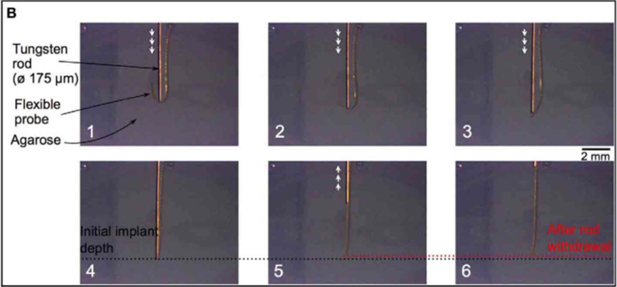
Insertion of a polyimide probe into agarose gel using a tungsten rod. The probe is easily visible through the gel, and the retraction of the probe after rod withdrawal (box 6) can be easily measured. Reproduced from [55]. CC BY 4.0.
Fluorescent imaging has been used in rare cases by coating the probes in a fluorescent dye, inserting the probes into live tissue, sacrificing the animal, then slicing and imaging the tissue parallel to the path of insertion [125]. This method shows promise for locating the probe in tissue, however the resolution is often too low to visualize a probe. In addition, probe location over time cannot be evaluated because the fluorescent dye is absorbed by the body if the tissue is not fixed shortly after insertion.
MRI and CT have been used to image the location of larger probes (such as SEEG or DBS probes, with average targeting accuracy of 1.6–5.0 mm), however they have not been widely used to locate flexible probes [5, 9, 66, 67]. When imaging probes, the MRI and CT detect the metal traces and electrodes in the probe, not the polymer backbone. Because there is such a small amount of metal in the devices and the resolution of the machines are not high enough, most flexible probes cannot be detected. Some work has been done using micro-CT to detect microelectrodes in tissue, however this method is not widely used at this time.
Histology has been used at the termination of in vivo experiments to determine the relative location of probes with respect to each other [10, 54] (figure 32). This provides valuable information within a single slice, however because of the distortion of the tissue during processing and slicing, it is difficult to get reliable location information from histology between different slices and with respect to the brain as a whole. In particular, it is difficult to determine the exact relationship of the electrode sites to adjacent neurons. Some probes have to be removed prior to slicing which further disrupts the tissue–device interface.
Figure 32.
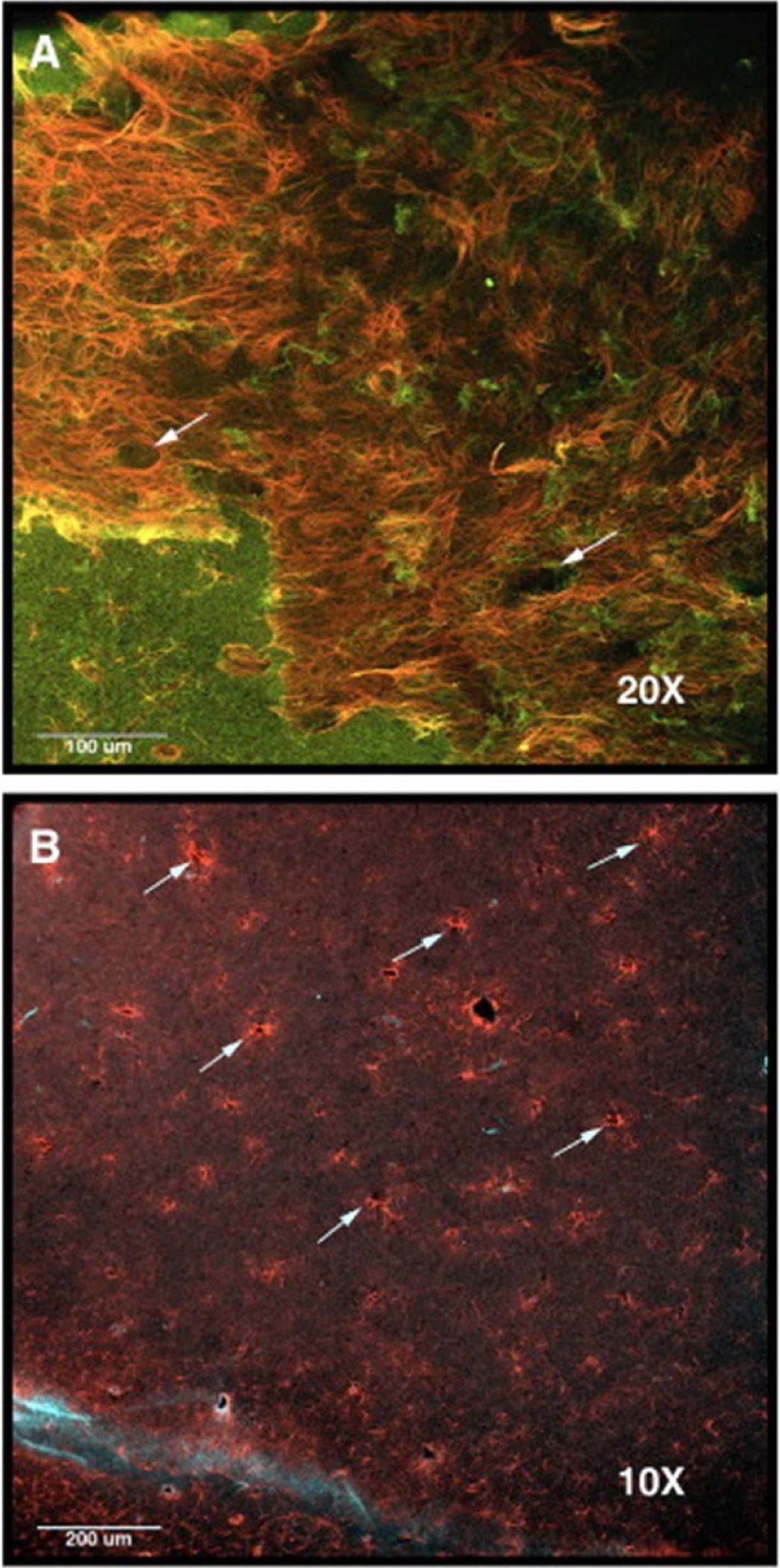
Histology image of a rat brain implanted with a multisite silicon array. Arrows point to holes in the tissue where the probe shanks were implanted. Images are stained to show (A) reactive astrocytes in red (anti-GFAP (glial fibrillary acidic protein)) and neurons in green (anti-beta-III tubulin), and (B) reactive astrocytes in red (anti-GFAP) and monocytes/macrophages in light blue (anti-CD68). Reprinted from [10], Copyright (2009), with permission from Elsevier.
For in vivo experiments with active electrical recordings or stimulation, electrical activity can be correlated with physiological response (for example, recording in brain areas which control breathing and simultaneously observing the breathing itself) [9]. This can be effective in some areas of the brain (when the physiological response is regular and easily recordable), but not possible for other areas (for example, the hippocampus where there is no observable physical response to brain activity).
Because most of these techniques are not optimized to view small, flexible probes, most studies do not evaluate probe targeting. The evaluations of targeting accuracy in the remainder of this section are theorized based on fundamental properties of the insertion technique.
The insertion methods which likely produce the most accurately located probes are the shuttle and injection methods, as they allows the probe to be guided to its target with a relatively rigid structure which is unlikely to bend or move during insertion. The magnetically guided insertion would also likely produce accurate placement of probes as it allows the surgeon to directly guide the tip, however there is no published data to support this hypothesis.
Slightly lower accuracy targeting is possible via insertion methods which have less support at the tip of the probe, such as the use of dissolvable stiffeners, stiffness changing materials, engineered cross sections, or stiff tipped probes. Each of these methods provides some support to the entire length of the shank, but to a lesser extent than a shuttle or magnetically guided probe. In the case of dissolvable stiffeners or stiffness changing materials, the probe can begin to soften as it is inserted, allowing it to deviate around any inhomogeneities in the tissue (such as blood vessels). In probes with engineered cross sections, any sort of torsion on the probe (again, caused by inhomogeneities in the tissue) can lead to bending of the probe away from its target. With stiff-tipped probes, the initial insertion is identical to that of a rigid probe insertion, but after the tip is fully inserted into the tissue, the flexible cable allows the probe to deviate inside the tissue.
The least accurate targeting is achieved through unaided, guided, and braced insertion. Each of these strategies functions by supporting the device above the tissue, so when the probe is inserted into the tissue, it is free to bend and deviate from its planned path. Even relatively stiff probes may experience some bending due to anatomical features.
7.4. Surgical difficulty
Surgical difficulty is characterized by the number of steps required for successful insertion and the overall difficulty of each step. The methods which are the easiest to implement surgically are those which do not require any extra steps or training, such as the unaided, stiff-tipped, and engineered cross section insertion methods. In each of these techniques, the probe itself is designed to allow for a standard, simple insertion.
Several insertion methods require more delicate handling, making them slightly more difficult to perform. For example, probes with a dissolvable stiffener may be brittle (depending on the properties of the stiffener) and require extra care to ensure there is no damage to the probe prior to insertion. Similarly, with a stiffness-changing material, the surgeon must work quickly in order to ensure the material remains sufficiently stiff during insertion (i.e. so it does not begin to soften prematurely upon exposure to body temperature or body fluid). Additionally, many of these coatings dissolve when exposed to water or saline, so they must be stored in a dry environment to prevent pre-surgical damage.
Some methods, while not inherently difficult, require extra training to ensure they are performed properly. When using a dissolvable brace, the probe is advanced in a standard way, but must be paused periodically to dissolve the bottom portion of the brace. Although each of the steps in this process is somewhat simple, it requires care to ensure it is done correctly and that too much of the brace is not dissolved away. For the injection method, after the needle is inserted, the device (suspended in saline) must be injected at the same rate that the needle is retracted to ensure no damage to the device and proper placement. For magnetic insertion, the magnetic field must be properly aligned prior to insertion to ensure the probe is inserted in the intended direction.
Finally, some methods are characteristically more difficult and require extra training to perform. One such example is the shuttle insertion method, which requires patience and training to learn to separate the shuttle from the probe and ensure that the probe is not retracted with the shuttle. The difficulty of this process relies heavily on the design of the probe/shuttle system. Another example of a more difficult insertion method is the use of an insertion guide. Depending on the design of the guide and insertion system, there are varying degrees of difficulty in aligning the probe to the guide and removing the guide after insertion.
7.5. Tissue immune response
Most insertion studies do not evaluate the immune response after insertion, however there is some supporting data for the more common insertion methods. In general, the methods which insert the bare probe on its own (unaided, guided, and braced) tend to have the smallest immune response because the material remains flexible during the entire insertion, allowing it to bend around features like blood vessels rather than cut through them. Histological evaluation of flexible probes implanted acutely (2 h duration) via the dissolvable brace method detected stab wounds matching the probe dimensions with no evidence of blood cells, indicating that very little or no bleeding occurred [54]. In contrast, a similar acute insertion for blunt-tipped wires of 0.24 mm diameter resulted in bleeding observable on histology images [119]. Methods which use small volumes of rigid materials (for example, small shuttles or thin dissolvable coatings) also show very minimal immune response in the immediate vicinity of the probe [60, 63, 175] as compared to methods which utilize larger rigid materials (such as larger shuttles or thick dissolvable coatings) [141].
After the initial acute response, the glial sheath begins to form, which can easily be seen using standard histology techniques. For the best recording and stimulation performance, the distance between the electrode and tissue should be as small as possible. Therefore, the thickness of the glial sheath should be minimized. Thicker glial sheaths tend to be associated with probes built from non-flexible materials. After implantation for 4–12 weeks, a thick glial scar in the range of 50–100 μm on each side of the probe was observed using rigid silicon probes of 14–130 μm thickness and 200 μm width [49, 108]. This is similar to the scarring observed for a magnetically inserted probe (with a semi-rigid cable consisting of FeNi alloy coated in polyimide) after 5 weeks, which yielded a scar of 100–200 μm thickness per side (probe cross section 6 × 20 μm2) [168]. When using thin dissolvable coatings, the glial sheath is generally thinner after 7–29 weeks implanted, ranging from 3 to 60 μm thick on each side of the probe (using parylene and polyimide probes with 1–14 μm thickness, saccharose, dextran, PLGA, or CMC coatings with 13–150 μm thickness) [60, 79, 151, 152]. A histological image following removal of a 14 μm thick parylene probe coated in 13 μm thick dextran after 4 months of implantation is shown in figure 33. One study evaluated the differences in glial scarring for implants and coatings of different sizes. Dissolvable CMC shuttles were molded with two different widths (100 and 300 μm) but identical thickness and length (125 μm and 1.5 mm), and then implanted for 12 weeks. Histology revealed a significantly larger glial scar, with a total thickness of 120 μm, when using the wider shuttle as compared to the narrow shuttle, with a total thickness of 3.6 μm, indicating that the overall cross section of all implanted materials plays a large role in glial scarring [79]. Parylene and polyimide probes (5–48 × 70–300 μm2 cross sections) inserted with rigid shuttles (of unknown dimensions) for 4–5 weeks exhibited thinner glial scars of approximately 25 μm thickness [141, 176]. Histology associated with a 200 μm thick polyimide probe inserted with a tungsten rod is shown in figure 34. Similar to shuttle-inserted probes, injected mesh structures (SU-8 with 0.5 × 5–20 μm2 threads) implanted for 2–5 weeks produced thin glial scars that were less than 50 μm thick [110, 111]. All data described in this section is summarized in table 6.
Figure 33.
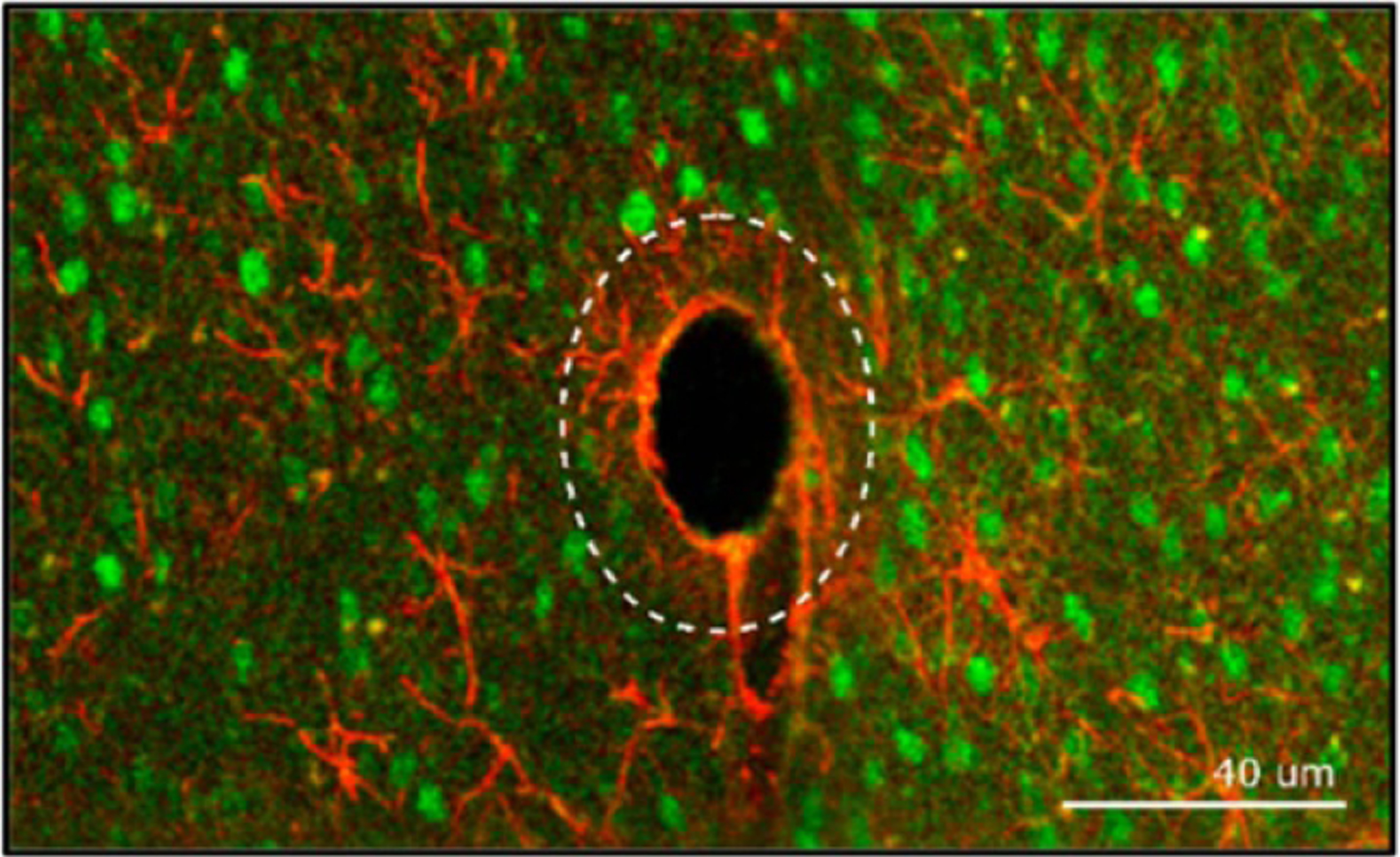
Confocal imaging of a flexible parylene probe (14 μm thickness, tapered 218–72 μm width) inserted using a dissolvable dextran stiffener. Image shows reactive astrocytes (anti-GFAP) in red and the neuronal nuclei in green. The dotted line represents the size of the coated electrode prior to dissolution of the stiffener. The presence of neurons (green) inside the dotted line indicates that the neurons were able to recover after dissolution of the coating. The thick line of astrocytes (red) shows the location of the glial scar, which is approximately 3 μm thick. Reproduced from [60]. CC BY 3.0.
Figure 34.
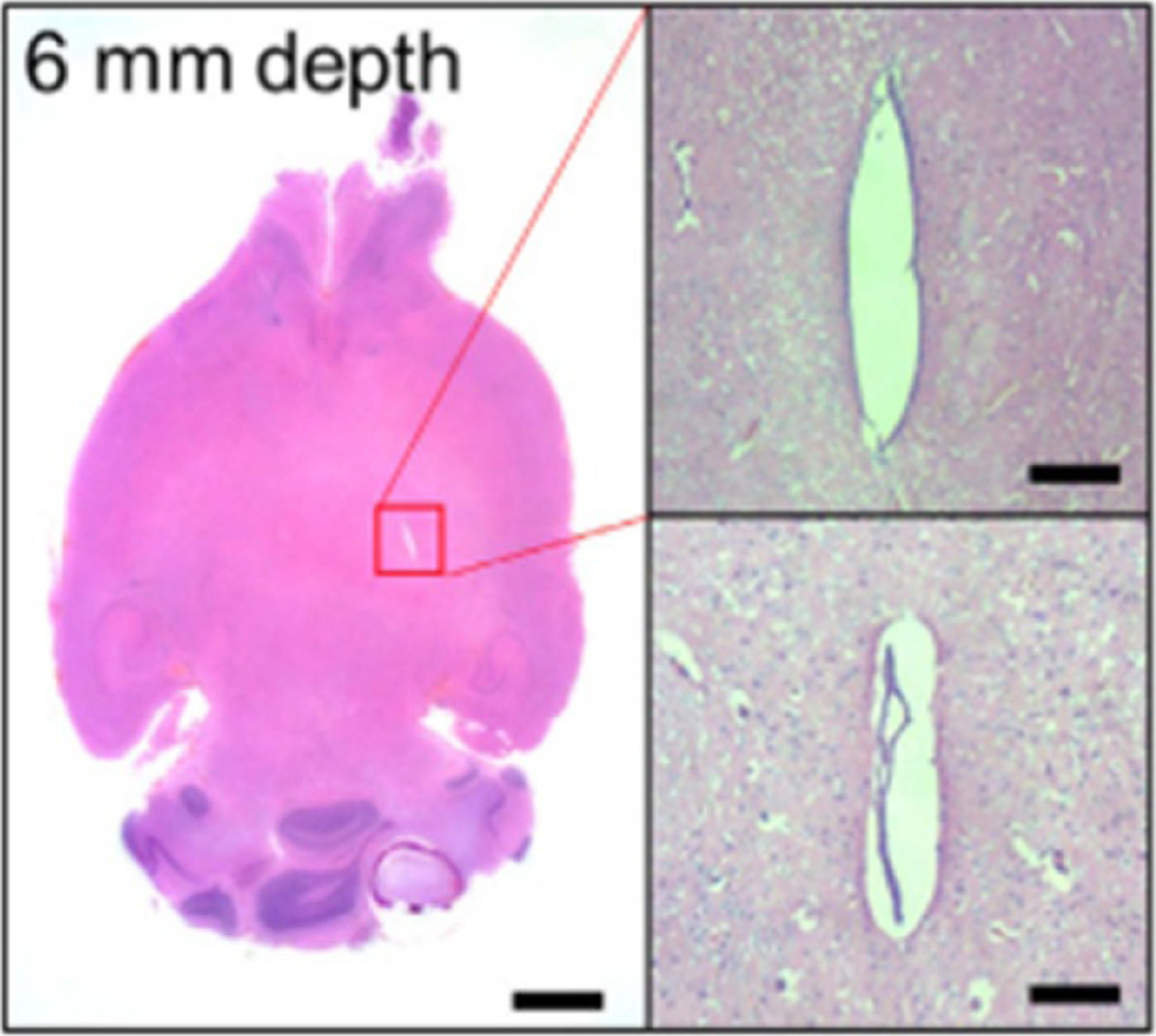
Histological analysis of a flexible polyimide probe (20 × 350 μm2 cross section) inserted using a tungsten shuttle. Image shows an H&E stained tissue slice at 6 mm depth 30 d after implant. There is no evidence if an ongoing immune reaction, however a fibrosis measuring approximately 50 × 350 μm2 is present. Scale bars are 500 μm (left) and 50 μm (right). Reprinted from [141], Copyright (2018), with permission from Elsevier.
Table 6.
Examples of typical glial scar thickness for each insertion technique.
| Insertion technique | Material(s) and cross section dimensions | Length of implant | Cross section dimensions | Glial scar thickness (each side of implant)a |
|---|---|---|---|---|
| Rigid probe [49, 108] | Silicon | 4–12 weeks | 14–130 × 200 μm2 | 50–500 μm |
| Magnetically guided [168] | Polyimide/FeNi alloy | 5 weeks | 6 × 20 μm2 | 100–200 μm |
| Dissolvable stiffener [60, 79, 151, 152] | Polyimide (probe) Saccharose (coating) |
7–29 weeks | 10 × 270 μm2 (probe) 20–45 μm thick (coating) |
50 μm |
| Polyimide (probe) PLGA polymer (coating) |
4 months | 1 × 350 μm2 (probe) 100 μm thick (coating) |
20 μm | |
| Parylene (probe) | 4 months | 14 × 218 μm2 (probe) 13 μm thick (coating) |
3 μm | |
| No probe CMC (shuttle) | 12 weeks | 125 × 100 μm2 (shuttle) | 1.8 μm | |
| 125 × 300 μm2 (shuttle) | 60 μm | |||
| Shuttle [141, 176] | Polyimide (probe) Tungsten rod (shuttle) |
30 d | 20 × 300 μm2 (probe) Unknown shuttle size |
25 μm |
| Parylene (probe) Metal (shuttle) | 4 weeks | 48 × 70 μm2 with 5 × 100 μm2 lateral structure (probe) Unknown shuttle size |
25 μm | |
| Injection [110, 111] | SU-8 (probe) Glass (needle) | 2 weeks | 0.5 × 5–30 μm2 (threads) 650 μm (needle diameter) | 20–50 μm |
Listed scar thickness is on either side of the implant, i.e. the distance to the target tissue. Total scar thickness is double the listed value.
Published research on stiff-tipped and engineered cross section probes do not currently include evaluation of the immune response. The immune response can be hypothesized by comparing to similar insertion methods (for example, stiff-tipped probes likely have a response magnitude between that of bare probes and probes inserted with a shuttle because of their similarities to these two methods), however there is currently no published data to support this claim.
In addition to the insertion method, the probe design itself impacts the immune response and resulting glial encapsulation. Most probes have a similar shape (a long, slender probe), however some groups have evaluated probes with open architecture or other features into which the microglia can travel and form a scar. The presence of perforations in the probe has not been shown to impact the magnitude of scarring, however the encapsulation does travel into the sheath of the probe (see figure 35) [176, 177]. This type of scarring likely makes removal of the device difficult, however further investigation is necessary to determine other effects of this geometry.
Figure 35.
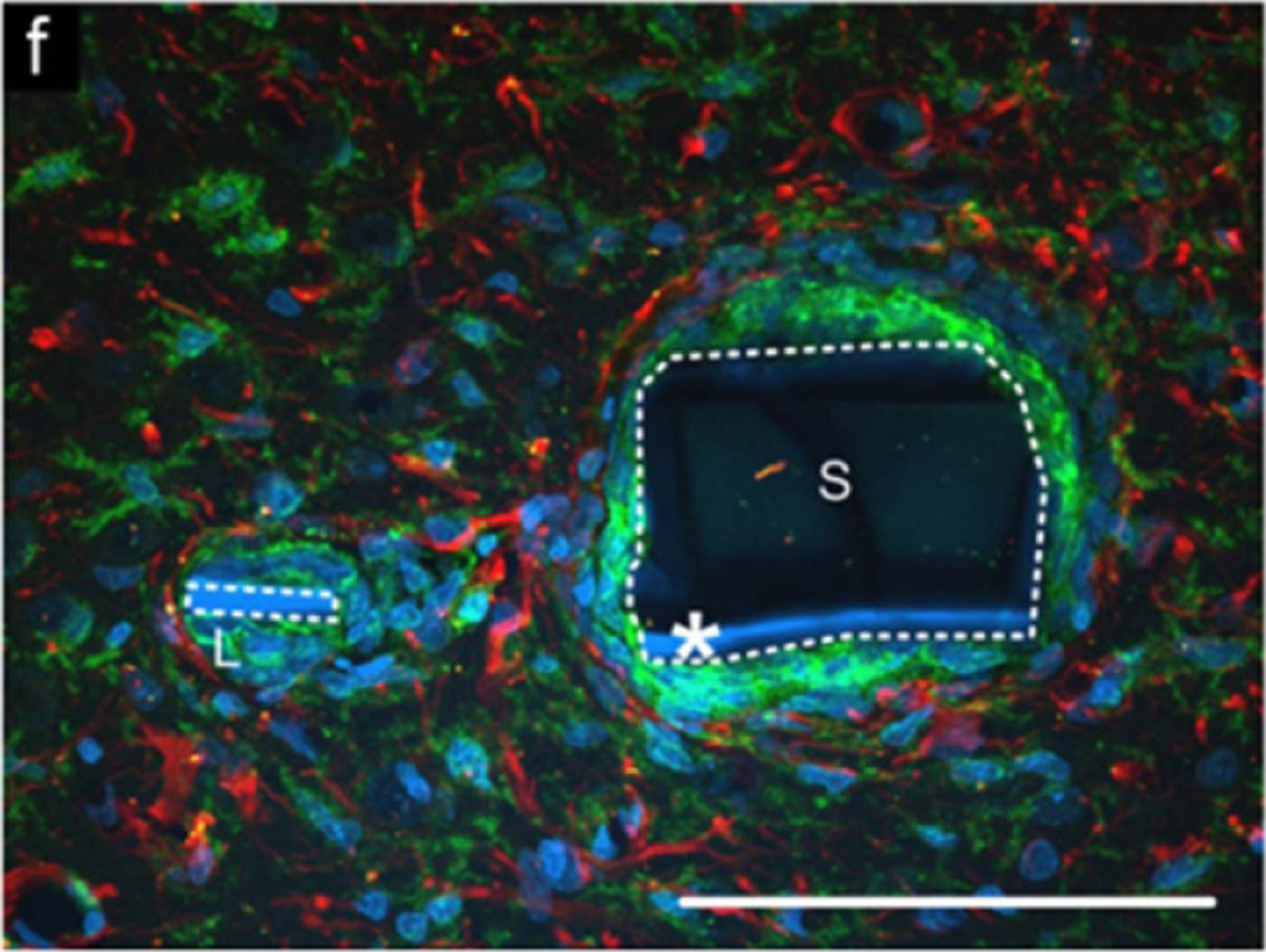
Immunohistochemical analysis of an open architecture probe. The white dotted line outlines the two parts of the probe, with the space between them being a perforation. The image shows an overlay of reactive astrocytes (anti-GFAP) in red and microglia and macrophages (OX-42) in green. Scale bar is 100 μm. Reprinted from [176], Copyright (2007), with permission from Elsevier.
7.6. Overall limitations
In the comparisons of surgical difficulty, targeting, and immune response, it is assumed that the probe is sized such that a successful insertion is possible (namely, that the cross section is large enough and/or the length is short enough to prevent buckling). In order to satisfy this assumption, there are certain limitations of each insertion method that must be considered. Many of these limitations are discussed in detail in the insertion techniques section of this review, but briefly summarized here and in table 7.
For unaided, guided, and stiff-tipped insertion, the probe itself must be sufficiently large (cross section), short, or stiff in order to be successfully inserted without buckling. Similarly, currently available stiffness changing materials are not sufficiently stiff when fabricated in thin layers, so the probes and/or coatings must be sufficiently large and short.
When inserting with a shuttle, a dissolvable adhesive (such as PEG) is often used to adhere the probe to the shuttle. It is often difficult to detach the probe from the shuttle, resulting in a slight retraction of the probe while the shuttle is removed. In most cases, this can be characterized and corrected by inserting the probe slightly past the target area.
When using dissolvable stiffeners or braces, the biggest limitation is the inability to retract and reinsert the device if it is incorrectly placed. In many cases, electrical recordings are collected during surgery to determine if the device is receiving a signal. If the device is not in the correct area, there is no way to re-insert it, because the brace or stiffener is dissolved during the first insertion. In addition, if the dissolvable coating is blocking the electrodes, recording during insertion is not possible.
Overall, devices with engineered cross sections have very few limitations, but the fabrication process can be prohibitively difficult. For devices built with vertical struts, highly anisotropic etching and very accurate alignment is required to achieve the desired geometry. For devices with curved cross sections, highly delicate fixturing and thermoforming (to achieve the desired shape) is necessary. Both of these processes are difficult and may suffer from low yield during fabrication.
Magnetically-guided devices rely on a magnetic material at the tip of the device, however the majority of biocompatible metals are non-magnetic. Published magnetically-guided devices use either a copper magnet wire or an iron alloy, neither of which are approved as a biocompatible implantable material. As such, devices using this technique would likely have a greater immune response and would not be functional for long term recording or stimulation.
For injectable devices, the main limitation is that the entire device must fit through a needle. As such, the device must not be packaged prior to insertion, which leads to more handling after insertion (and higher likelihood of shifting the device out of position).
7.7. Requirements for human use
Although flexible neural probes are currently exclusively used for research in animal models, it is important to keep the requirements for human use devices in mind. Currently, the only penetrating neural probes approved for human use are DBS and SEEG probes (FDA approved for chronic use) and the Utah array (FDA approved for investigational use for up to 30 d implantation). The main obstacles preventing flexible probes from FDA approval (and Utah arrays from full approval) are the low number of electrode sites per device, lack of efficacy over time, and poor targeting accuracy [182].
For devices to be effective in research or clinical purposes, multiple recording or stimulation electrodes are often needed. DBS and SEEG probes generally have 4–10 large electrodes, often with numerous additional microelectrodes along the length of the probe [6, 29, 32], while the most commonly used Utah array has 100 electrodes [43, 44]. Early versions of many research devices have only one electrode at the tip (such as microwires and carbon fibers), however more advanced devices (such as multisite silicon probes and most flexible probes) have multiple electrodes along the length of a single probe.
One of the biggest issues currently faced for research probes is the lack of efficacy over time. This is due to two major causes: glial scarring, and device wear and tear. Glial scarring, as discussed in section 7.5, is significantly less pronounced in flexible devices with small cross sections that are inserted using methods that do not cause significant bleeding. If the glial scar is sufficiently thin and the electrodes remain close to the target tissue, the device can continue to function over long periods of time. Device wear and tear is an issue that is commonly seen in neural devices. As an example, Utah arrays have an average recording lifetime of 12 months due to breakdown of the device by the immune system [182]. Flexible devices are often plagued with this issue as well due to the permeability of most polymers to water and ions in the body. Of the studies cited in this review, the flexible probe which remained functional for the longest period of time was implanted for only two years [100], while most other studies were terminated after weeks or months of implantation.
Another major issue with flexible devices is the poor targeting accuracy, which is discussed in sections 6 and 7.3. For devices to perform their function properly, they must be implanted in the correct area. For flexible devices with small electrode sizes, the targeting accuracy becomes even more critical, as the electrode can only stimulate or record from tissue within a small distance.
In addition to these issues specific to flexible probes, there are a host of issues encountered by all devices that must be met prior to FDA approval, such as biocompatibility of materials, surgical risk, and mechanical compatibility with surrounding tissue. Any devices which are implanted into neural tissue are considered a Class III (high risk) medical device, and are thus subject to the most stringent set of testing requirements [182].
8. Conclusion
Flexible microelectrode arrays have been shown to evoke a lesser immune response and to be more successful in chronic neural recording and stimulation. Without insertion aids, flexible probes are limited to accessing shallow cortical areas because of their low buckling force as compared to the force required to insert the probe into brain tissue.
To achieve successful and useful long term recordings in deep brain areas (and improve the efficacy of animal experiments), flexible microelectrode arrays with multiple electrodes must be developed alongside an insertion method that allows for accurate placement with minimal tissue response. The fabrication of arrays and response to chronic implantation has been widely studied and, more recently, insertion techniques are being advanced and published to allow flexible probes to be more widely used. Because this research is relatively new, however, it is important to review the many insertion techniques that have been developed to evaluate which method is best for any given application.
Moving forward, more research is needed to further refine the insertion methods discussed in this review. The majority of studies discuss the insertion of one probe at a time, however it is often more useful to implant many probes simultaneously in the targeted brain area to allow for high density recording and stimulation. In addition, more work is needed to evaluate if probes accurately reach their target locations via the imaging methods discussed in this review or other methods that have not yet been developed.
As more research is performed, more complex questions will arise, which will necessitate the use of larger animal models. The majority of in vivo flexible microelectrode array research thus far has been performed in rodent models because many brain areas can be reached with a short probe. As larger animal models are used, the need for deeper insertions (and more effective insertion methods) will become more critical.
Acknowledgments
This work was funded by the NSF under Award Number CBET-1343193 and the NIH under Award Number U01NS099703.
Data availability statement
No new data were created or analysed in this study.
References
- [1].Reif PS, Strzelczyk A and Rosenow F 2016. The history of invasive EEG evaluation in epilepsy patients Seizure 41 191–5 [DOI] [PubMed] [Google Scholar]
- [2].La Vaque TJ 1999. The history of EEG hans berger J. Neurother 3 1–9 [Google Scholar]
- [3].Hayne R, Meyers R and Knott JR 1949. Characteristics of electrical activity of human corpus striatum and neighboring structures J. Neurophysiol 12 189–95 [DOI] [PubMed] [Google Scholar]
- [4].Gildenberg PL 2006. History of electrical neuromodulation for chronic pain Pain Med 7 S7–S13 [Google Scholar]
- [5].D’Agostino E, Kanter J, Song Y and Aronson JP 2020. Stereoencephalography electrode placement accuracy and utility using a frameless insertion platform without a rigid cannula Oper. Neurosurg 18 409–16 [DOI] [PubMed] [Google Scholar]
- [6].Kahan J, Papadaki A, White M, Mancini L, Yousry T, Zrinzo L, Limousin P, Hariz M, Foltynie T and Thornton J 2015. The safety of using body-transmit MRI in patients with implanted deep brain stimulation devices PLoS One 10 e0129077. [DOI] [PMC free article] [PubMed] [Google Scholar]
- [7].ChunXiang T and Jiping H 2005. Monitoring insertion force and electrode impedance during implantation of microwire electrodes 2005 Int. Conf. IEEE Engineering in Medicine and Biology Society (Shanghai: IEEE; ) pp 7333–6 [DOI] [PubMed] [Google Scholar]
- [8].Musallam S, Bak MJ, Troyk PR and Andersen RA 2007. A floating metal microelectrode array for chronic implantation J. Neurosci. Methods 160 122–7 [DOI] [PubMed] [Google Scholar]
- [9].Arafat MA, Rubin LN, Jefferys JGR and Irazoqui PP 2019. A method of flexible micro-wire electrode insertion in rodent for chronic neural recording and a device for electrode insertion IEEE Trans. Neural Syst. Rehabil. Eng 27 1724–31 [DOI] [PubMed] [Google Scholar]
- [10].Ward MP, Rajdev P, Ellison C and Irazoqui PP 2009. Toward a comparison of microelectrodes for acute and chronic recordings Brain Res 1282 183–200 [DOI] [PubMed] [Google Scholar]
- [11].Tucker Davis Technologies 2021. Electrodes (https://www.tdt.com/components/electrodes/) (Accessed 13 3 2020)
- [12].Allen Institute for Brain Science 2021. Allen Brain Map (https://portal.brain-map.org/) (Accessed 13 3 2020)
- [13].Papp EA, Leergaard TB, Calabrese E, Johnson GA and Bjaalie JG 2014. Waxholm space atlas of the sprague dawley rat brain Neuroimage 97 374–86 [DOI] [PMC free article] [PubMed] [Google Scholar]
- [14].Nitzsche B, Frey S, Collins LD, Seeger J, Lobsien D, Dreyer A, Kirsten H, Stoffel MH, Fonov VS and Boltze J 2015. A stereotaxic, population-averaged T1w ovine brain atlas including cerebral morphology and tissue volumes Front. Neuroanat 9 69. [DOI] [PMC free article] [PubMed] [Google Scholar]
- [15].Franklin MS, Kraemer GW, Shelton SE, Baker E, Kalin NH and Uno H 2000. Gender differences in brain volume and size of corpus callosum and amygdala of rhesus monkey measured from MRI images Brain Res 852 263–7 [DOI] [PubMed] [Google Scholar]
- [16].Sahin B, Aslan H, Unal B, Canan S, Bilgic S, Kaplan S and Tumkaya L 2011. Brain volumes of the lamb, rat and bird do not show hemispheric asymmetry: a stereological study Image Anal. Stereol 20 9–13 [Google Scholar]
- [17].Lüders E, Steinmetz H and Jäncke L 2002. Brain size and grey matter volume in the healthy human brain Neuroreport 13 2371–4 [PubMed] [Google Scholar]
- [18].Cheung KC 2007. Implantable microscale neural interfaces Biomed. Microdevices 9 923–38 [DOI] [PubMed] [Google Scholar]
- [19].Schwartz AB, Cui XT, Weber DJ and Moran DW 2006. Brain-controlled interfaces: movement restoration with neural prosthetics Neuron 52 205–20 [DOI] [PubMed] [Google Scholar]
- [20].Blackrock Microsystems 2018. Utah Array (https://www.blackrockmicro.com/electrode-types/utah-array/) (Accessed 13 3 2020)
- [21].Neuronexus 2021. Probe Finder (https://neuronexus.com/products/probe-finder/) (Accessed 13 3 2020)
- [22].Jorfi M, Skousen JL, Weder C and Capadona JR 2015. Progress towards biocompatible intracortical microelectrodes for neural interfacing applications J. Neural Eng 12 011001. [DOI] [PMC free article] [PubMed] [Google Scholar]
- [23].Kook G, Lee SW, Lee HC, Cho I-J and Lee HJ 2016. Neural probes for chronic applications Micromachines 7 179. [DOI] [PMC free article] [PubMed] [Google Scholar]
- [24].Lacour SP, Courtine G and Guck J 2016. Materials and technologies for soft implantable neuroprostheses Nat. Rev. Mater 1 16063 [Google Scholar]
- [25].Bamford JA, Todd KG and Mushahwar VK 2010. The effects of intraspinal microstimulation on spinal cord tissue in the rat Biomaterials 31 5552–63 [DOI] [PMC free article] [PubMed] [Google Scholar]
- [26].Mueller M, De La Oliva N, Del Valle J, Delgado-Martinez I, Navarro X and Stieglitz T 2017. Rapid prototyping of flexible intrafascicular electrode arrays by picosecond laser structuring J. Neural Eng 14 066016. [DOI] [PubMed] [Google Scholar]
- [27].Larson CE and Meng E 2020. A review for the peripheral nerve interface designer J. Neurosci. Methods 332 108523. [DOI] [PubMed] [Google Scholar]
- [28].Tallgren P, Vanhatalo S, Kaila K and Voipio J 2005. Evaluation of commercially available electrodes and gels for recording of slow EEG potentials Clin. Neurophysiol 116 799–806 [DOI] [PubMed] [Google Scholar]
- [29].Ad-Tech Medical Instrument Corporation 2021. Depth Electrodes (https://adtechmedical.com/depth-electrodes) (Accessed 13 3 2020)
- [30].Dubey A and Ray S 2019. Cortical electrocorticogram (ECoG) is a local signal J. Neurosci 39 4299–311 [DOI] [PMC free article] [PubMed] [Google Scholar]
- [31].Choi J, Kim S-M, Ryu R-H, Kim S-P and Sohn J 2018. Implantable neural probes for brain-machine interfaces—current developments and future prospects Exp. Neurobiol 27 453–71 [DOI] [PMC free article] [PubMed] [Google Scholar]
- [32].NeuroPace, Inc. 2021. NeuroPace RNS System (https://www.neuropace.com/the-rns-system/) (Accessed 13 3 2020)
- [33].Connolly AT, Muralidharan A, Hendrix C, Johnson L, Gupta R, Stanslaski S, Denison T, Baker KB, Vitek JL and Johnson MD 2015. Local field potential recordings in a non-human primate model of Parkinsons disease using the Activa PC + S neurostimulator J. Neural Eng 12 066012. [DOI] [PMC free article] [PubMed] [Google Scholar]
- [34].Nevrotech 2017. Microwire Arrays—MMA (https://nevrotech.com/products/multichannel-arrays/microwire-arrays/) (Accessed 13 3 2020)
- [35].Patel PR, Na K, Zhang H, Kozai TDY, Kotov NA, Yoon E and Chestek CA 2015. Insertion of linear 8.4 μm diameter 16 channel carbon fiber electrode arrays for single unit recordings J. Neural Eng 12 046009. [DOI] [PMC free article] [PubMed] [Google Scholar]
- [36].Lourenço CF, Caetano M, Ledo A and Barbosa RM 2019. Platinized carbon fiber-based glucose microbiosensor designed for metabolic studies in brain slices Bioelectrochemistry 130 107325. [DOI] [PubMed] [Google Scholar]
- [37].Koh DS and Hille B 1999. Rapid fabrication of plastic-insulated carbon-fiber electrodes for micro-amperometry J. Neurosci. Methods 88 83–91 [DOI] [PubMed] [Google Scholar]
- [38].Nicolai EN, Michelson NJ, Settell ML, Hara SA, Trevathan JK, Asp AJ, Stocking KC, Lujan JL, Kozai TDY and Ludwig KA 2018. Design choices for next-generation neurotechnology can impact motion artifact in electrophysiological and fast-scan cyclic voltammetry measurements Micromachines 9 494. [DOI] [PMC free article] [PubMed] [Google Scholar]
- [39].Patel PR, Zhang H, Robbins MT, Nofar JB, Marshall SP, Kobylarek MJ, Kozai TDY, Kotov NA and Chestek CA 2016. Chronic in vivo stability assessment of carbon fiber microelectrode arrays J. Neural Eng 13 066002. [DOI] [PMC free article] [PubMed] [Google Scholar]
- [40].Peters JL, Miner LH, Michael AC and Sesack SR 2004. Ultrastructure at carbon fiber microelectrode implantation sites after acute voltammetric measurements in the striatum of anesthetized rats J. Neurosci. Methods 137 9–23 [DOI] [PubMed] [Google Scholar]
- [41].Armstrong-James M and Millar J 1979. Carbon fibre microelectrodes J. Neurosci. Methods 1 279–87 [DOI] [PubMed] [Google Scholar]
- [42].Malagodi MS, Horch KW and Schoenberg AA 1989. An intrafascicular electrode for recording of action potentials in peripheral nerves Ann. Biomed. Eng 17 397–410 [DOI] [PubMed] [Google Scholar]
- [43].Rousche PJ and Normann RA 1992. A method for pneumatically inserting an array of penetrating electrodes into cortical tissue Ann. Biomed. Eng 20 413–22 [DOI] [PubMed] [Google Scholar]
- [44].Maynard EM, Nordhausen CT and Normann RA 1997. The utah intracortical electrode array: a recording structure for potential brain-computer interfaces Electroencephalogr. Clin. Neurophysiol 102 228–39 [DOI] [PubMed] [Google Scholar]
- [45].Blackrock Microsystems 2018. Utah Rodent Array (https://www.blackrockmicro.com/utah-rodent-array/) (Accessed 13 3 2020)
- [46].Karumbaiah L, Saxena T, Carlson D, Patil K, Patkar R, Gaupp EA, Betancur M, Stanley GB, Carin L and Bellamkonda RV 2013. Relationship between intracortical electrode design and chronic recording function Biomaterials 34 8061–74 [DOI] [PubMed] [Google Scholar]
- [47].Scott KM, Du J, Lester HA and Masmanidis SC 2012. Variability of acute extracellular action potential measurements with multisite silicon probes J. Neurosci. Methods 211 22–30 [DOI] [PMC free article] [PubMed] [Google Scholar]
- [48].Barz F, Livi A, Lanzilotto M, Maranesi M, Bonini L, Paul O and Ruther P 2017. Versatile, modular 3D microelectrode arrays for neuronal ensemble recordings: from design to fabrication, assembly, and functional validation in non-human primates J. Neural Eng 14 036010. [DOI] [PubMed] [Google Scholar]
- [49].Biran R, Martin DC and Tresco PA 2007. The brain tissue response to implanted silicon microelectrode arrays is increased when the device is tethered to the skull J. Biomed. Mater. Res. A 82A 169–78 [DOI] [PubMed] [Google Scholar]
- [50].Inácio AR, Nasretdinov A, Lebedeva J and Khazipov R 2016. Sensory feedback synchronizes motor and sensory neuronal networks in the neonatal rat spinal cord Nat. Commun 7 13060. [DOI] [PMC free article] [PubMed] [Google Scholar]
- [51].Seo D, Carmena JM, Rabaey JM, Maharbiz MM and Alon E 2015. Model validation of untethered, ultrasonic neural dust motes for cortical recording J. Neurosci. Methods 244 114–22 [DOI] [PubMed] [Google Scholar]
- [52].Rabaey JM 2011. Brain-machine interfaces as the new frontier in extreme miniaturization 2011 Proc. European Solid-State Device Research Conf. (ESSDERC) (Helsinki: IEEE; ) pp 19–24 [Google Scholar]
- [53].Seo D, Neely RM, Shen K, Singhal U, Alon E, Rabaey JM, Carmena JM and Maharbiz MM 2016. Wireless recording in the peripheral nervous system with ultrasonic neural dust Neuron 91 529–39 [DOI] [PubMed] [Google Scholar]
- [54].Wang X, Hirschberg AW, Xu H, Slingsby-Smith Z, Lecomte A, Scholten K, Song D and Meng E 2020. A parylene neural probe array for multi-region deep brain recordings J. Microelectromech. Syst 29 499–513 [DOI] [PMC free article] [PubMed] [Google Scholar]
- [55].Richter A. et al. A simple implantation method for flexible, multisite microelectrodes into rat brains. Front. Neuroeng. 2013;6:6. doi: 10.3389/fneng.2013.00006. [DOI] [PMC free article] [PubMed] [Google Scholar]
- [56].Na K, Sperry ZJ, Lu J, Vöröslakos M, Parizi SS, Bruns TM, Yoon E and Seymour JP 2020. Novel diamond shuttle to deliver flexible neural probe with reduced tissue compression Microsyst. Nanoeng 6 37. [DOI] [PMC free article] [PubMed] [Google Scholar]
- [57].Kato Y, Saito I, Hoshino T, Suzuki T and Mabuchi K 2006. Preliminary study of multichannel flexible neural probes coated with hybrid biodegradable polymer 2006 Int. Conf. of the IEEE Engineering in Medicine and Biology Society (New York: IEEE; ) pp 660–3 [DOI] [PubMed] [Google Scholar]
- [58].Chen CH, Chuang SC, Lee YT, Yeh SR, Chang YC and Yao DJ 2010. Three-dimensional flexible microprobe for recording the neural signal J. Micro/Nanolithogr. MEMS MOEMS 9 031007 [Google Scholar]
- [59].Lo M, Wang S, Singh S, Damodaran VB, Kaplan HM, Kohn J, Shreiber DI and Zahn JD 2015. Coating flexible probes with an ultra fast degrading polymer to aid in tissue insertion Biomed. Microdevices 17 34. [DOI] [PMC free article] [PubMed] [Google Scholar]
- [60].Kil D, Carmona MB, Ceyssens F, Deprez M, Brancato L, Nuttin B, Balschun D and Puers R 2019. Dextran as a resorbable coating material for flexible neural probes Micromachines 10 61. [DOI] [PMC free article] [PubMed] [Google Scholar]
- [61].Xiang Z, Yen S-C, Xue N, Sun T, Tsang WM, Zhang S, Liao L-D, Thakor NV and Lee C 2014. Ultra-thin flexible polyimide neural probe embedded in a dissolvable maltose-coated microneedle J. Micromech. Microeng 24 065015 [Google Scholar]
- [62].Wu F, Im M and Yoon E 2011. A flexible fish-bone-shaped neural probe strengthened by biodegradable silk coating for enhanced biocompatibility 2011 16th Int. Solid-State Sensors, Actuators and Microsystems Conf (Beijing: IEEE; ) pp 966–9 [Google Scholar]
- [63].Luan L. et al. Ultraflexible nanoelectronic probes form reliable, glial scar–free neural integration. Sci. Adv. 2017;3:e1601966. doi: 10.1126/sciadv.1601966. [DOI] [PMC free article] [PubMed] [Google Scholar]
- [64].Richardson DE and Akil H 1977. Pain reduction by electrical brain stimulation in man. II. Chronic self administration in the periventricular gray matter J. Neurosurg 47 184–94 [DOI] [PubMed] [Google Scholar]
- [65].Elwassif MM, Datta A, Rahman A and Bikson M 2012. Temperature control at DBS electrodes using a heat sink: experimentally validated FEM model of DBS lead architecture J. Neural Eng 9 046009. [DOI] [PMC free article] [PubMed] [Google Scholar]
- [66].Burchiel KJ, McCartney S, Lee A and Raslan AM 2013. Accuracy of deep brain stimulation electrode placement using intraoperative computed tomography without microelectrode recording J. Neurosurg 119 301–6 [DOI] [PubMed] [Google Scholar]
- [67].Nowell M, Rodionov R, Diehl B, Wehner T, Zombori G, Kinghorn J, Ourselin S, Duncan J, Miserocchi A and McEvoy A 2014. A novel method for implementation of frameless stereoEEG in epilepsy surgery Oper. Neurosurg 10 525–33 [DOI] [PMC free article] [PubMed] [Google Scholar]
- [68].Sinnamon HM and Schwartzbaum JS 1973. Dorsal hippocampal unit and EEG responses to rewarding and aversive brain stimulation in rats Brain Res 56 183–202 [DOI] [PubMed] [Google Scholar]
- [69].Lee B, Zubair MN, Marquez YD, Lee DM, Kalayjian LA, Heck CN and Liu CY 2015. A single-center experience with the neuropace RNS system: a review of techniques and potential problems World Neurosurg 84 719–26 [DOI] [PubMed] [Google Scholar]
- [70].Frederick Haer Co. 2021. FHC Frame Stereotactic Microelectrodes and Insertion Tubes (https://www.fh-co.com/product/frame-stereotactic-microelectrodes-insertion-tubes/) (Accessed 4 3 2021)
- [71].Binder DK, Rau GM and Starr PA 2005. Risk factors for hemorrhage during microelectrode-guided deep brain stimulator implantation for movement disorders Neurosurgery 56 722–32 [DOI] [PubMed] [Google Scholar]
- [72].Jiman AA, Ratze DC, Welle EJ, Patel PR, Richie JM, Bottorff EC, Seymour JP, Chestek CA and Bruns TM 2020. Multi-channel intraneural vagus nerve recordings with a novel high-density carbon fiber microelectrode array Sci. Rep 10 15501. [DOI] [PMC free article] [PubMed] [Google Scholar]
- [73].Blackrock Microsystems 2018. Neuroport Array (https://www.blackrockmicro.com/neuroport-array/) (Accessed 4 6 2020)
- [74].Barrese JC, Aceros J and Donoghue JP 2016. Scanning electron microscopy of chronically implanted intracortical microelectrode arrays in non-human primates J. Neural Eng 13 026003. [DOI] [PMC free article] [PubMed] [Google Scholar]
- [75].Leber M, Shandhi MMH, Hogan A, Solzbacher F, Bhandari R and Negi S 2016. Different methods to alter surface morphology of high aspect ratio structures Appl. Surf. Sci 365 180–90 [DOI] [PMC free article] [PubMed] [Google Scholar]
- [76].Barrese JC, Rao N, Paroo K, Triebwasser C, Vargas-Irwin C, Franquemont L and Donoghue JP 2016. Failure mode analysis of silicon-based intracortical microelectrode arrays in non-human primates J. Neural Eng 10 066014. [DOI] [PMC free article] [PubMed] [Google Scholar]
- [77].Zeater N, Cheong SK, Solomon SG, Dreher B and Martin PR 2015. Binocular visual responses in the primate lateral geniculate nucleus Curr. Biol 25 3190–5 [DOI] [PubMed] [Google Scholar]
- [78].Polikov VS, Tresco PA and Reichert WM 2005. Response of brain tissue to chronically implanted neural electrodes J. Neurosci. Methods 148 1–18 [DOI] [PubMed] [Google Scholar]
- [79].Kozai TDY, Gugel Z, Li X, Gilgunn PJ, Khilwani R, Ozdoganlar OB, Fedder GK, Weber DJ and Cui XT 2014. Chronic tissue response to carboxymethyl cellulose based dissolvable insertion needle for ultra-small neural probes Biomaterials 35 9255–68 [DOI] [PubMed] [Google Scholar]
- [80].Kozai TDY, Marzullo TC, Hooi F, Langhals NB, Majewska AK, Brown EB and Kipke DR 2010. Reduction of neurovascular damage resulting from microelectrode insertion into the cerebral cortex using in vivo two-photon mapping J. Neural Eng 7 046011. [DOI] [PMC free article] [PubMed] [Google Scholar]
- [81].Elkin BS, Ilankovan A and Morrison BI 2010. Age-dependent regional mechanical properties of the rat hippocampus and cortex J. Biomech. Eng 132 011010. [DOI] [PubMed] [Google Scholar]
- [82].Elkin BS, Azeloglu EU, Costa KD and Morrison BI 2007. Mechanical heterogeneity of the rat hippocampus measured by atomic force microscope indentation J. Neurotrauma 24 812–22 [DOI] [PubMed] [Google Scholar]
- [83].Maikos JT, Elias RAI and Shreiber DI 2008. Mechanical properties of dura mater from the rat brain and spinal cord J. Neurotrauma 25 38–51 [DOI] [PubMed] [Google Scholar]
- [84].Taylor Z and Miller K 2004. Reassessment of brain elasticity for analysis of biomechanisms of hydrocephalus J. Biomech 37 1263–9 [DOI] [PubMed] [Google Scholar]
- [85].Green MA, Bilston LE and Sinkus R 2008. In vivo brain viscoelastic properties measured by magnetic resonance elastography NMR Biomed 21 755–64 [DOI] [PubMed] [Google Scholar]
- [86].Choi H-Y 2001. Numerical human head model for traumatic injury assessment KSME Int. J 15 995–1001 [Google Scholar]
- [87].McGarvey KA, Lee JM and Boughner DR 1984. Mechanical suitability of glycerol-preserved human dura mater for construction of prosthetic cardiac valves Biomaterials 5 109–17 [DOI] [PubMed] [Google Scholar]
- [88].Normand V, Lootens DL, Amici E, Plucknett KP and Aymard P 2000. New insight into agarose gel mechanical properties Biomacromolecules 1 730–8 [DOI] [PubMed] [Google Scholar]
- [89].Gent AN 1958. On the relation between indentation hardness and Young’s modulus Rubber Chem. Technol 31 896–906 [Google Scholar]
- [90].HD Microsystems 2013. HD MicroSystems Product Selection Guide (http://web.mit.edu/scholvin/www/nt245/Documents/resists.PI.ProductSelectorGuide.pdf) (Accessed 13 12 2019)
- [91].MatWeb 2021. Overview of Materials for Polyimide (http://www.matweb.com/search/datasheet_print.aspx?matguid=ab35b368ab9c40848f545c35bdf1a672) (Accessed 13 12 2019)
- [92].Xu T, Yoo JH, Babu S, Roy S, Lee J-B and Lu H 2016. Characterization of the mechanical behavior of SU-8 at microscale by viscoelastic analysis J. Micromech. Microeng 26 105001 [Google Scholar]
- [93].MatWeb 2021. Dow CYCLOTENE™ 3022–35 Bisbenzocyclobutene (BCB) Electronic Resin (http://www.matweb.com/search/datasheet_print.aspx?matguid=71ffed3308f24b5a91cfa101a0ca85fd) (Accessed 13 12 2019)
- [94].Specialty Coating Systems (SCS) 2021. SCS Parylene Properties (https://scscoatings.com/wp-content/uploads/2017/09/02-SCS-Parylene-Properties-1016.pdf) (Accessed 13 12 2019)
- [95].MatWeb 2021. Overview of Materials for Liquid Crystal Polymer (LCP), Unfilled (http://www.matweb.com/search/datasheet_print.aspx?matguid=f1436e63c0a44e80a6f116cb87cbbebf) (Accessed 13 12 2019)
- [96].The Engineering Toolbox 2003. Young’s Modulus—Tensile and Yield Strength for Common Materials (https://www.engineeringtoolbox.com/young-modulus-d_417.html) (Accessed 13 12 2019)
- [97].MEMSnet 1997. Material: Silicon (Si), Bulk (https://www.memsnet.org/material/siliconsibulk/) (Accessed 13 12 2019)
- [98].AZO Materials 2021. Platinum—Properties and Applications (https://www.azom.com/properties.aspx?ArticleID=601) (Accessed 13 12 2019)
- [99].Ohsawa T, Miwa M, Kawade M and Tsushima E 1990. Axial compressive strength of carbon fiber J. Appl. Polym. Sci 39 1733–43 [Google Scholar]
- [100].Sohal HS, Jackson A, Jackson R, Clowry GJ, Vassilevski K, O’Neill A and Baker SN 2014. The sinusoidal probe: a new approach to improve electrode longevity Front. Neuroeng 7 10. [DOI] [PMC free article] [PubMed] [Google Scholar]
- [101].Groothuis J, Ramsey NF, Ramakers GMJ and Van Der Plasse G 2014. Physiological challenges for intracortical electrodes Brain Stimul 7 1–6 [DOI] [PubMed] [Google Scholar]
- [102].Lind G, Linsmeier CE and Schouenborg J 2013. The density difference between tissue and neural probes is a key factor for glial scarring Sci. Rep 3 2942. [DOI] [PMC free article] [PubMed] [Google Scholar]
- [103].Kozai TDY, Vazquez AL, Weaver CL, Kim S-G and Cui XT 2012. In vivo two-photon microscopy reveals immediate microglial reaction to implantation of microelectrode through extension of processes J. Neural Eng 9 066001. [DOI] [PMC free article] [PubMed] [Google Scholar]
- [104].Scott A, Weir K, Easton C, Huynh W, Moody WJ and Folch A 2013. A microfluidic microelectrode array for simultaneous electrophysiology, chemical stimulation, and imaging of brain slices Lab Chip 13 527–35 [DOI] [PMC free article] [PubMed] [Google Scholar]
- [105].Bjornsson CS, Oh SJ, Al-Kofahi YA, Lim YJ, Smith KL, Turner JN, De S, Roysam B, Shain W and Kim SJ 2006. Effects of insertion conditions on tissue strain and vascular damage during neuroprosthetic device insertion J. Neural Eng 3 196–207 [DOI] [PubMed] [Google Scholar]
- [106].Lewitus D, Smith KL, Shain W and Kohn J 2011. Ultrafast resorbing polymers for use as carriers for cortical neural probes Acta Biomater 7 2483–91 [DOI] [PubMed] [Google Scholar]
- [107].Wang J, Wagner F, Borton DA, Zhang J, Ozden I, Burwell RD, Nurmikko AV, Van Wagenen R, Diester I and Deisseroth K 2012. Integrated device for combined optical neuromodulation and electrical recording for chronic in vivo applications J. Neural Eng 9 016001. [DOI] [PubMed] [Google Scholar]
- [108].Turner JN, Shain W, Szarowski DH, Andersen M, Martins S, Isaacson M and Craighead H 1999. Cerebral astrocyte response to micromachined silicon implants Exp. Neurol 156 33–49 [DOI] [PubMed] [Google Scholar]
- [109].Chung K et al. 2013. Structural and molecular interrogation of intact biological systems Nature 497 332–7 [DOI] [PMC free article] [PubMed] [Google Scholar]
- [110].Zhou T, Hong G, Fu T-M, Yang X, Schuhmann TG, Viveros RD and Lieber CM 2017. Syringe-injectable mesh electronics integrate seamlessly with minimal chronic immune response in the brain Proc. Natl Acad. Sci 114 5894–9 [DOI] [PMC free article] [PubMed] [Google Scholar]
- [111].Liu J et al. 2015. Syringe injectable electronics Nat. Nanotechnol 10 629–36 [DOI] [PMC free article] [PubMed] [Google Scholar]
- [112].Tien LW, Wu F, Tang-Schomer MD, Yoon E, Omenetto FG and Kaplan DL 2013. Silk as a multifunctional biomaterial substrate for reduced glial scarring around brain-penetrating electrodes Adv. Funct. Mater 23 3185–93 [Google Scholar]
- [113].Jensen W, Yoshida K and Hofmann UG 2006. In-vivo implant mechanics of flexible, silicon-based ACREO microelectrode arrays in rat cerebral cortex IEEE Trans. Biomed. Eng 53 934–40 [DOI] [PubMed] [Google Scholar]
- [114].Pothof F, Bonini L, Lanzilotto M, Livi A, Fogassi L, Orban GA, Paul O and Ruther P 2016. Chronic neural probe for simultaneous recording of single-unit, multi-unit, and local field potential activity from multiple brain sites J. Neural Eng 13 046006. [DOI] [PubMed] [Google Scholar]
- [115].Zátonyi A. et al. A softening laminar electrode for recording single unit activity from the rat hippocampus. Sci. Rep. 2019;9:2321. doi: 10.1038/s41598-019-39835-6. [DOI] [PMC free article] [PubMed] [Google Scholar]
- [116].Agorelius J, Tsanakalis F, Friberg A, Thorbergsson PT, Pettersson LME and Schouenborg J 2015. An array of highly flexible electrodes with a tailored configuration locked by gelatin during implantation-initial evaluation in cortex cerebri of awake rats Front. Neurosci 9 331. [DOI] [PMC free article] [PubMed] [Google Scholar]
- [117].Lai H-Y, Liao L-D, Lin C-T, Hsu J-H, He X, Chen Y-Y, Chang J-Y, Chen H-F, Tsang S and Shih Y-Y I 2012. Design, simulation and experimental validation of a novel flexible neural probe for deep brain stimulation and multichannel recording J. Neural Eng 9 036001. [DOI] [PubMed] [Google Scholar]
- [118].Yoshida Kozai TD and Kipke DR 2009. Insertion shuttle with carboxyl terminated self-assembled monolayer coatings for implanting flexible polymer neural probes in the brain J. Neurosci. Methods 184 199–205 [DOI] [PMC free article] [PubMed] [Google Scholar]
- [119].Casanova F, Carney PR and Sarntinoranont M 2014. In vivo evaluation of needle force and friction stress during insertion at varying insertion speed into the brain J. Neurosci. Methods 237 79–89 [DOI] [PMC free article] [PubMed] [Google Scholar]
- [120].Chung JE. et al. Chronic implantation of multiple flexible polymer electrode arrays. J. Vis. Exp. 2019;152:e59957. doi: 10.3791/59957. [DOI] [PMC free article] [PubMed] [Google Scholar]
- [121].Lecomte A, Castagnola V, Descamps E, Dahan L, Blatché MC, Dinis TM, Leclerc E, Egles C and Bergaud C 2015. Silk and PEG as means to stiffen a parylene probe for insertion in the brain: toward a double time-scale tool for local drug delivery J. Micromech. Microeng 25 125003 [Google Scholar]
- [122].Wester BA, Lee RH and LaPlaca MC 2009. Development and characterization of in vivo flexible electrodes compatible with large tissue displacements J. Neural Eng 6 024002. [DOI] [PMC free article] [PubMed] [Google Scholar]
- [123].Jaroch DB, Irazoqui P and Rickus JL 2014. Flexible Neural Probe for Magnetic Insertion 8,761,898 B2 [DOI] [PubMed]
- [124].Shoffstall AJ, Srinivasan S, Willis M, Stiller AM, Ecker M, Voit WE, Pancrazio JJ and Capadona JR 2018. A mosquito inspired strategy to implant microprobes into the brain Sci. Rep 8 122. [DOI] [PMC free article] [PubMed] [Google Scholar]
- [125].Lee SE, Jun SB, Lee HJ, Kim J, Lee SW, Im C, Shin H-C, Chang JW and Kim SJ 2012. A flexible depth probe using liquid crystal polymer IEEE Trans. Biomed. Eng 59 2085–94 [DOI] [PubMed] [Google Scholar]
- [126].Khilwani R, Gilgunn PJ, Kozai TDY, Ong XC, Korkmaz E, Gunalan PK, Cui XT, Fedder GK and Ozdoganlar OB 2016. Ultra-miniature ultra-compliant neural probes with dissolvable delivery needles: design, fabrication and characterization Biomed. Microdevices 18 97. [DOI] [PubMed] [Google Scholar]
- [127].Sharp AA, Ortega AM, Restrepo D, Curran-Everett D and Gall K 2009. In vivo penetration mechanics and mechanical properties of mouse brain tissue at micrometer scales IEEE Trans. Biomed. Eng 56 45–53 [DOI] [PMC free article] [PubMed] [Google Scholar]
- [128].Egert D, Peterson RL and Najafi K 2011. Parylene microprobes with engineered stiffness and shape for improved insertion 2011 16th Int. Solid-State Sensors, Actuators and Microsystems Conf (Beijing: IEEE; ) pp 198–201 [Google Scholar]
- [129].Capadona JR, Tyler DJ, Zorman CA, Rowan SJ and Weder C 2012. Mechanically adaptive nanocomposites for neural interfacing MRS Bull 37 581–9 [DOI] [PMC free article] [PubMed] [Google Scholar]
- [130].Joo HR. et al. A microfabricated, 3D-sharpened silicon shuttle for insertion of flexible electrode arrays through dura mater into brain. J. Neural Eng. 2019;16:066021. doi: 10.1088/1741-2552/ab2b2e. [DOI] [PMC free article] [PubMed] [Google Scholar]
- [131].Hess AE, Capadona JR, Shanmuganathan K, Hsu L, Rowan SJ, Weder C, Tyler DJ and Zorman CA 2011. Development of a stimuli-responsive polymer nanocomposite toward biologically optimized, MEMS-based neural probes J. Micromech. Microeng 21 054009 [Google Scholar]
- [132].Obaid A, Wu Y-W, Hanna M, Jáidar O, Nix W, Ding J and Melosh N 2020. Ultra-sensitive measurement of brain penetration mechanics and blood vessel rupture with microscale probes bioRxiv 2020.09.21.306498 (Accessed 16 3 2021) [Google Scholar]
- [133].Lu L et al. 2018. Wireless optoelectronic photometers for monitoring neuronal dynamics in the deep brain Proc. Natl Acad. Sci 115 E1374–83 [DOI] [PMC free article] [PubMed] [Google Scholar]
- [134].Burton A et al. 2020. Wireless, battery-free subdermally implantable photometry systems for chronic recording of neural dynamics Proc. Natl Acad. Sci 117 2835–45 [DOI] [PMC free article] [PubMed] [Google Scholar]
- [135].Tijero M, Gabriel G, Caro J, Altuna A, Hernández R, Villa R, Berganzo J, Blanco FJ, Salido R and Fernández LJ 2009. SU-8 microprobe with microelectrodes for monitoring electrical impedance in living tissues Biosens. Bioelectron 24 2410–6 [DOI] [PubMed] [Google Scholar]
- [136].Mercanzini A, Cheung K, Buhl DL, Boers M, Maillard A, Colin P, Bensadoun J-C, Bertsch A and Renaud P 2008. Demonstration of cortical recording using novel flexible polymer neural probes Sensors Actuators A 143 90–96 [Google Scholar]
- [137].Chung JE et al. 2019. High-density, long-lasting, and multi-region electrophysiological recordings using polymer electrode arrays Neuron 101 21–31 [DOI] [PMC free article] [PubMed] [Google Scholar]
- [138].Felix SH, Shah KG, Tolosa VM, Sheth HJ, Tooker AC, Delima TL, Jadhav SP, Frank LM and Pannu SS 2013. Insertion of flexible neural probes using rigid stiffeners attached with biodissolvable adhesive J. Vis. Exp 79 e50609. [DOI] [PMC free article] [PubMed] [Google Scholar]
- [139].Felix S, Shah K, George D, Tolosa V, Tooker A, Sheth H, Delima T and Pannu S 2012. Removable silicon insertion stiffeners for neural probes using polyethylene glycol as a biodissolvable adhesive 2012 Int. Conf. IEEE Engineering in Medicine and Biology Society (San Diego, CA: IEEE; ) pp 871–4 [DOI] [PubMed] [Google Scholar]
- [140].Kim BJ, Kuo JTW, Hara SA, Lee CD, Yu L, Gutierrez CA, Hoang TQ, Pikov V and Meng E 2013. 3D Parylene sheath neural probe for chronic recordings J. Neural Eng 10 045002. [DOI] [PubMed] [Google Scholar]
- [141].Kim JH, Lee GH, Kim S, Chung HW, Lee JH, Lee SM, Kang CY and Lee SH 2018. Flexible deep brain neural probe for localized stimulation and detection with metal guide Biosens. Bioelectron 117 436–43 [DOI] [PubMed] [Google Scholar]
- [142].Wei X, Luan L, Zhao Z, Li X, Zhu H, Potnis O and Xie C 2018. Nanofabricated ultraflexible electrode arrays for high-density intracortical recording Adv. Sci 5 1700625. [DOI] [PMC free article] [PubMed] [Google Scholar]
- [143].Zhang S. et al. A removable insertion shuttle for ultraflexible neural probe implantation with stable chronic brain electrophysiological recording. Adv. Mater. Interfaces. 2020;7:1901775. [Google Scholar]
- [144].Takeuchi S, Ziegler D, Yoshida Y, Mabuchi K and Suzuki T 2005. Parylene flexible neural probes integrated with microfluidic channels Lab Chip 5 519–23 [DOI] [PubMed] [Google Scholar]
- [145].Guan S. et al. Elastocapillary self-assembled neurotassels for stable neural activity recordings. Sci. Adv. 2019;5:eaav2842. doi: 10.1126/sciadv.aav2842. [DOI] [PMC free article] [PubMed] [Google Scholar]
- [146].Seo KJ, Artoni P, Qiang Y, Zhong Y, Han X, Shi Z, Yao W, Fagiolini M and Fang H 2019. Transparent, flexible, penetrating microelectrode arrays with capabilities of single-unit electrophysiology Adv. Biosyst 3 1800276. [DOI] [PubMed] [Google Scholar]
- [147].Wu F, Tien LW, Chen F, Berke JD, Kaplan DL and Yoon E 2015. Silk-backed structural optimization of high-density flexible intracortical neural probes J. Microelectromech. Syst 24 62–69 [Google Scholar]
- [148].Lecomte A, Degache A, Descamps E, Dahan L and Bergaud C 2017. In vitro and in vivo biostability assessment of chronically-implanted parylene C neural sensors Sensors Actuators B 251 1001–8 [Google Scholar]
- [149].Singh A, Zhu H and He J 2004. Improving mechanical stiffness of coated benzocyclobutene (BCB) based neural implant 2004 Int. Conf. of the IEEE Engineering in Medicine and Biology Society (San Francisco, CA: IEEE; ) pp 4298–301 [DOI] [PubMed] [Google Scholar]
- [150].Kil D, Brancato L and Puers R 2017. Dextran as a fast resorbable and mechanically stiff coating for flexible neural probes J. Phys. Conf. Ser 922 012016 [Google Scholar]
- [151].Hassler C, Guy J, Nietzschmann M, Plachta DTT, Staiger JF and Stieglitz T 2016. Intracortical polyimide electrodes with a bioresorbable coating Biomed. Microdevices 18 81. [DOI] [PubMed] [Google Scholar]
- [152].Ceyssens F, Bovet Carmona M, Kil D, Deprez M, Tooten E, Nuttin B, Takeoka A, Balschun D, Kraft M and Puers R 2019. Chronic neural recording with probes of subcellular cross-section using 0.06 mm2 dissolving microneedles as insertion device Sensors Actuators B 284 369–76 [Google Scholar]
- [153].Ramos KJ and Bahr DF 2007. Mechanical behavior assessment of sucrose using nanoindentation J. Mater. Res 22 2037–45 [Google Scholar]
- [154].Tabari M. Investigation of carboxymethyl cellulose (CMC) on mechanical properties of cold water fish gelatin biodegradable edible films. Foods. 2017;6:41. doi: 10.3390/foods6060041. [DOI] [PMC free article] [PubMed] [Google Scholar]
- [155].Yagi S, Yamagiwa S, Kubota Y, Sawahata H, Numano R, Imashioya T, Oi H, Ishida M and Kawano T 2015. Dissolvable base scaffolds allow tissue penetration of high-aspect-ratio flexible microneedles Adv. Healthc. Mater 4 1949–55 [DOI] [PubMed] [Google Scholar]
- [156].Xu H, Hirschberg AW, Scholten K, Berger TW, Song D and Meng E 2018. Acute in vivo testing of a conformal polymer microelectrode array for multi-region hippocampal recordings J. Neural Eng 15 016017. [DOI] [PMC free article] [PubMed] [Google Scholar]
- [157].Andrei A, Tutunjyan N, Verbinnen G, VanPut S, Krylychkina O, Eberle W and Musa S 2012. Fabrication and successful in-vivo implantation of a flexible neural implant with a hybrid polyimide-silicon design 2012 Int. Conf. of the IEEE Engineering in Medicine and Biology Society (San Diego, CA: IEEE; ) pp 3890–3 [DOI] [PubMed] [Google Scholar]
- [158].Wen X et al. 2019. Flexible, multifunctional neural probe with liquid metal enabled, ultra-large tunable stiffness for deep-brain chemical sensing and agent delivery Biosens. Bioelectron 131 37–45 [DOI] [PMC free article] [PubMed] [Google Scholar]
- [159].Rezaei S, Xu Y and Pang SW 2019. Control of neural probe shank flexibility by fluidic pressure in embedded microchannel using PDMS/PI hybrid substrate PLoS One 14 e0220258. [DOI] [PMC free article] [PubMed] [Google Scholar]
- [160].Stiller AM. et al. Chronic intracortical recording and electrochemical stability of thiol-ene/acrylate shape memory polymer electrode arrays. Micromachines. 2018;9:500. doi: 10.3390/mi9100500. [DOI] [PMC free article] [PubMed] [Google Scholar]
- [161].Arreaga-Salas DE, Avendaño-Bolívar A, Simon D, Reit R, Garcia-Sandoval A, Rennaker RL and Voit W 2015. Integration of high-charge-injection-capacity electrodes onto polymer softening neural interfaces ACS Appl. Mater. Interfaces 7 26614–23 [DOI] [PubMed] [Google Scholar]
- [162].Ware T, Simon D, Arreaga-Salas DE, Reeder J, Rennaker R, Keefer EW and Voit W 2012. Fabrication of responsive, softening neural interfaces Adv. Funct. Mater 22 3470–9 [Google Scholar]
- [163].Simon DM et al. 2017. Design and demonstration of an intracortical probe technology with tunable modulus J. Biomed. Mater. Res. A 105A 159–68 [DOI] [PMC free article] [PubMed] [Google Scholar]
- [164].Hess-Dunning A and Tyler DJ 2018. A mechanically-adaptive polymer nanocomposite-based intracortical probe and package for chronic neural recording Micromachines 9 583. [DOI] [PMC free article] [PubMed] [Google Scholar]
- [165].Harris JP, Capadona JR, Miller RH, Healy BC, Shanmuganathan K, Rowan SJ, Weder C and Tyler DJ 2011. Mechanically adaptive intracortical implants improve the proximity of neuronal cell bodies J. Neural Eng 8 066011. [DOI] [PMC free article] [PubMed] [Google Scholar]
- [166].Ejserholm F, Stegmayr J, Bauer P, Johansson F, Wallman L, Bengtsson M and Oredsson S 2015. Biocompatibility of a polymer based on off-stoichiometry thiol-enes + epoxy (OSTE+) for neural implants Biomater. Res 19 19. [DOI] [PMC free article] [PubMed] [Google Scholar]
- [167].Hoffmann R. Verfahren zur Kortex-Insertion von Polyimid-Mikroelektroden. Albert Ludwigs Universität Freiburg; 2008. Ph.D. dissertation. [Google Scholar]
- [168].Gao L, Wang J, Guan S, Du M, Wu K, Xu K, Zou L, Tian H and Fang Y 2019. Magnetic actuation of flexible microelectrode arrays for neural activity recordings Nano Lett 19 8032–9 [DOI] [PubMed] [Google Scholar]
- [169].Dryg ID, Ward MP, Qing KY, Mei H, Schaffer JE and Irazoqui PP 2015. Magnetically inserted neural electrodes: tissue response and functional lifetime IEEE Trans. Neural Syst. Rehabil. Eng 23 562–71 [DOI] [PubMed] [Google Scholar]
- [170].Yang X, Zhou T, Zwang TJ, Hong G, Zhao Y, Viveros RD, Fu T-M, Gao T and Lieber CM 2019. Bioinspired neuron-like electronics Nat. Mater 18 510–7 [DOI] [PMC free article] [PubMed] [Google Scholar]
- [171].Hong G, Fu T-M, Zhou T, Schuhmann TG, Huang J and Lieber CM 2015. Syringe injectable electronics: precise targeted delivery with quantitative input/output connectivity Nano Lett 15 6979–84 [DOI] [PubMed] [Google Scholar]
- [172].Schuhmann TG, Zhou T, Hong G, Lee JM, Fu T-M, Park H-G and Lieber CM 2018. Syringe-injectable mesh electronics for stable chronic rodent electrophysiology J. Vis. Exp 137 e58003. [DOI] [PMC free article] [PubMed] [Google Scholar]
- [173].Forte AE, Galvan S, Manieri F, Rodriguez Y Baena F and Dini D 2016. A composite hydrogel for brain tissue phantoms Mater. Des 112 227–38 [Google Scholar]
- [174].Lozoya M. Development of a Tissue-Mimicking Brain Phantom for Neurosurgical Pre-Operative Planning and Training. Clemson University; 2016. [Google Scholar]
- [175].Zhao Z, Li X, He F, Wei X, Lin S and Xie C 2019. Parallel, minimally-invasive implantation of ultra-flexible neural electrode arrays J. Neural Eng 16 035001. [DOI] [PMC free article] [PubMed] [Google Scholar]
- [176].Seymour JP and Kipke DR 2007. Neural probe design for reduced tissue encapsulation in CNS Biomaterials 28 3594–607 [DOI] [PubMed] [Google Scholar]
- [177].Hara SA, Kim BJ, Kuo JTW, Lee CD, Meng E and Pikov V 2016. Long-term stability of intracortical recordings using perforated and arrayed parylene sheath electrodes J. Neural Eng 13 066020. [DOI] [PubMed] [Google Scholar]
- [178].Hanson TL, Diaz-Botia CA, Kharazia V, Maharbiz MM and Sabes PN 2019. The ‘sewing machine’ for minimally invasive neural recording bioRxiv 578542 (Accessed 16 10 2019) [Google Scholar]
- [179].Musk E and Neuralink 2019. An integrated brain-machine interface platform with thousands of channels J. Med. Internet Res 21 e16194. [DOI] [PMC free article] [PubMed] [Google Scholar]
- [180].Ma J, Zhao Z, Cui S, Liu F-Y, Yi M and Wan Y 2019. A novel 3D-printed multi-drive system for synchronous electrophysiological recording in multiple brain regions Front. Neurosci 13 1322. [DOI] [PMC free article] [PubMed] [Google Scholar]
- [181].Viviani R 2016. A digital atlas of middle to large brain vessels and their relation to cortical and subcortical structures Front. Neuroanat 10 1–9 [DOI] [PMC free article] [PubMed] [Google Scholar]
- [182].Obidin N, Tasnim F and Dagdeviren C 2020. The future of neuroimplantable devices: a materials science and regulatory perspective Adv. Mater 32 1901482. [DOI] [PubMed] [Google Scholar]
Associated Data
This section collects any data citations, data availability statements, or supplementary materials included in this article.
Data Availability Statement
No new data were created or analysed in this study.


