

Abstract
There have been several orthodontic modalities for maxillary transverse control with most addressing symmetric control. The asymmetric transverse control of maxillary dentition is challenging to orthodontists due to the lack of certain modalities and possible dental side effects. Skeletal anchorages provide biomechanics without orthodontic side effects, but reports of their utilization for transverse control of maxillary dentition are scarce. The purpose of this article is to introduce a novel method utilizing two midpalatal orthodontic miniscrews and a connecting wire system for the asymmetric transverse control of maxillary dentition. Records of two patients consecutively treated with this system are reported, and the related biomechanical considerations are presented.
Keywords: Orthodontic miniscrew, Maxillary transverse control, Asymmetry
INTRODUCTION
A transverse discrepancy of the upper and lower dentition can cause a unilateral posterior crossbite, unilateral large posterior overjet, or both. Transverse asymmetry can be classified into skeletal and dental origins. Burstone1 insisted that the axial inclination of molars can be used as the basis of classification. According to him, a skeletal transverse asymmetry is a transverse discrepancy with a normal axial inclination of the molars, while a dental transverse asymmetry involves the unilateral abnormal axial inclination of the molars.1
The symmetric transverse discrepancy of upper and lower dentition can be treated with various proposed modalities: transpalatal arch (TPA), palatal expander, lingual arch, etc.2,3 If the patient is an adult with a skeletal transverse discrepancy, surgically assisted expansion or constriction of the maxilla is a viable option.4 However, if the nature of the transverse discrepancy is unilateral, which is the asymmetric transverse dimension of the dentition, the abovementioned modalities may not be optimal or valid methods. To overcome such a challenging situation, the sophisticated application of TPA or the use of unilateral posterior cross elastics has been suggested.3 If the asymmetric transverse dimension is of skeletal origin, a unilateral corticotomy or segmental osteotomy can be performed.5 However, orthodontic biomechanics always involve unwanted tooth movement in instances of dental anchorage, such as when pure unilateral expansion or constriction with a transpalatal arch or lingual arch is not possible and cross elastics may cause the extrusion of teeth and may induce side effects on the normal opposing dentition. Surgical options place a heavy burden on patients and have a poor cost-to-benefit ratio when the amount of discrepancy is small.
Skeletal anchorages have been actively used in clinical orthodontics in recent years. They provide absolute anchorage and avoid unwanted tooth movement. Adapting skeletal anchorage to correct the asymmetric transverse dimension of dentition can be an excellent biomechanical option. The aim of this report is to present a biomechanical method to control maxillary dentition transverse dimension in an asymmetrical way using two orthodontic miniscrews implanted in the palatal bone. In addition, two patients with asymmetric posterior overjet treated with the method are presented.
Two Midpalatal Miniscrews Connecting a Wire System
The authors have reported on midpalatal miniscrews connected to a wire system for the three-dimensional control of maxillary dentition in a previous article.6 The midpalatal area is suitable for miniscrew implantation with high stability and low failure rates7 because of the following reasons: (1) the absence of important anatomic structures including major nerves or blood vessels, (2) no risk of contacting dental roots, and (3) adequate cortical bone thickness for the primary stability of the miniscrews.8,9 The placement of miniscrews and the fabrication of connecting wire is described in detail in a previous report.6 Briefly, the procedure is as follows: (1) Implantation of two miniscrews (screw size: 1.6 mm in diameter, 6 mm in length) with a slot on its head design that can accommodate a 0.215 × 0.250-inch rectangular wire. Miniscrews are placed approximately 2 mm to the left and right of the midpalatal suture. (2) A rubber impression is taken to create a plaster model with analog miniscrews. (3) A 0.215 × 0.250-inch stainless steel wire is bent to passively fit the miniscrew slots. (4) The wire is shaped to perform desired tooth movement and placed in the patient's oral cavity. Since the wire is removable, changing the wire with different designs for different tooth movements is possible without replanting or implanting additional miniscrews. Therefore, this is a multifunctional versatile system for the control of maxillary dentition.
Maxillary Dentition Transverse Control
We have developed two different miniscrew-connecting-wire designs for the transverse control of maxillary dentition: a TPA type and lingual arch type (Figures 1 and 2). The major difference is whether the wire is extended to the anterior part, which means that the horizontal transverse vector of force is weighted in the lingual arch type. Expansion or constriction can be performed by bending the wire arm in the desired direction. This activation can be done unilaterally or in opposing directions (eg, expansion on the right side and constriction on the left side).
Figure 1. .
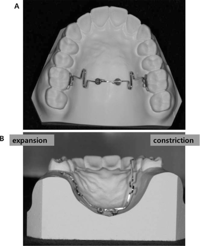
Transpalatal arch-type midpalatal miniscrews connecting wire. (A) Occlusal view of the appliance with the wires inserted into the lingual sheath of the first molars. (B) Coronal view from the posterior side of wire activated.
Figure 2. .
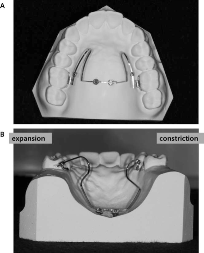
Lingual arch type midpalatal miniscrews connecting wire. (A) Occlusal view of the appliance with the wires inserted into the lingual sheath of the first molars. (B) Coronal view from the posterior side of wire activated.
The TPA type shown in Figure 1 has a short horizontal loop that allows for vertical control of the tooth. When performing expansion or constriction activation of the wire, a vertical vector will be created (Figure 1B). The horizontal loop is incorporated to control this intrusion or extrusion vector. This design also enables the simultaneous vertical control of teeth while performing transverse control (eg, extrusion with expansion).
The insertion angle of the wire into the lingual slot of the first molar can be adjusted differently. Burstone10 classified his precision lingual arch into nonparallel and parallel types on the basis of the insertion angle at expansion activation. When expansion activation is applied, the nonparallel type forms an angle with the bracket attached to the lingual side of the first molar where the wire arm will be tied. The parallel type is defined in cases where, when the wire is activated, its end is parallel to the bracket. For the parallel type, when the expanded wire arm is constricted for insertion into the brackets, the arm crosses the bracket at an angle creating equal and opposite couples that rotate the molars outward mesially. An opposite biomechanical situation happens for the nonparallel type: the expansion activation of the passively fit wire arms will create no rotation couples when they are constricted and tied into the brackets.
The same principles of biomechanics can be applied for the lingual arch-type appliance (Figure 3). When expansion activation is given with a bend on the wire to make its end parallel to the lingual sheath where the wire will be inserted, both expansion and mesial-out rotation will occur. If the wire arms expand without a bend so that the wire creates an angulation with the lingual sheath, only expansion occurs. For parallel-type expansion activation with the whole arch tied in a continuous arch wire, molar mesial-out rotation may result in greater expansion on the anterior part of the dentition, thereby making the arch form into a square shape. For nonparallel expansion activation, less expansion is expected on the anterior part of the dentition. This type of activation could be applied according to the extent of the posterior crossbite. If the crossbite involves only the first molar, then nonparallel activation that creates minor expansion on the premolars and canines will be more suitable. If the crossbite is more extensive and involves the mesial teeth, then parallel-type expansion activation that causes mesial-out rotation of the first molar resulting in more expansion of the premolars and canines is indicated.
Figure 3. .

Lingual arch type midpalatal miniscrews connecting wire. (A) Nonparallel type expansion. (B) Parallel type expansion activation. (C) Nonparallel type constriction activation. (D) Parallel type constriction activation.
In the case of constriction, the same principle, but an opposite direction of tooth movement compared to the expansion case, is expected.
Case 1
A 17-year-old man visited the Department of Orthodontics, Kyung Hee University Hospital at Gangdong, Seoul, Korea complaining of occlusal disharmony after he experienced the reduction of a maxillary fracture caused by a traffic accident a month ago. A postero-anterior (PA) cephalogram showed mandibular deviation to the right side, and intraoral examination showed an anterior open bite with crossbites on the posterior dentition (Figure 4). The open bite was planned to be corrected first by the intrusion of upper molars and subsequently control of the maxillary arch width to coordinate with the mandibular dentition.
Figure 4. .

Pretreatment intraoral photo of case 1.
The patient at the initial visit to the Department of Orthodontics exhibited a bilateral posterior crossbite that was supposedly due to the bilateral constriction of the maxilla. Therefore, a rapid palatal expander was delivered to bilaterally expand the maxilla. After 1 month of expansion, however, the expansion mainly occurred on the left side resulting in a large posterior overjet in the left posterior dentition and edge-to-edge overjet in the right posterior dentition. A 2-month period of bone consolidation was given before brackets were bonded and the palatal expander was removed. After aligning and leveling, two miniscrews with a rectangular slot on its head were implanted in the midpalatal area. Treatment of the transverse discrepancy by expansion of the upper right posterior dentition and simultaneous constriction of upper left posterior dentition was performed using a lingual arch type midpalatal miniscrews connecting wire engaged to the upper first molar sheaths. Since both expansion and constriction were needed to the anterior (canine) region, parallel activation was performed (Figure 5). A midpalatal wire with expansion activation for the right side and constriction activation for the left side was engaged. After 6 months of midpalatal wire application, the transverse discrepancy was resolved. Finishing and detailing of the occlusion was then performed (Figure 6). The total treatment duration was 19 months. Three-dimensional (3D) superimposition of the pretreatment and posttreatment maxillary cast models using palatal rugae as the reference point showed the expansion of the right molars and constriction of the left molars (Figure 6A). Pretreatment and posttreatment arch width measurements from the midpalatal suture to the right and left side of the first molars revealed 2- to 3-mm expansion and constriction that occurred after treatment (Table 1). The cast models showed that the expansion and constriction was mainly achieved by tipping of the posterior teeth. Also, the pretreatment and posttreatment PA cephalograms showed that the tipping of the posterior teeth occurred after treatment (Figure 7; Table 2).
Figure 5. .

Case 1 during treatment. (A) Lingual arch type midpalatal miniscrew connecting wire for asymmetric transverse control of maxillary dentition. Right side was expanded and left side was constricted. (B) Intraoral photos during treatment.
Figure 6. .

Case 1 after treatment. (A) Superimposition of 3D models before and after treatment (yellow: before treatment, green: after treatment). (B) Intraoral photos after completion of treatment.
Table 1. .
Summary of Transverse Width Changes (in mm) After Treatmenta

Figure 7. .

Postero-anterior cephalogram of before (left) and after (right) treatment of case 1. Note that the inclination of maxillary molars was changed after treatment. Right and left foramen rotundum connecting line was used as horizontal reference line.
Table 2. .
Summary of Buccolingual Inclination (in Degrees) Changes Before and After Treatment of the Case 1 Measured From Postero-Anterior Cephalograma

Case 2
A 28-year-old woman visited the Department of Orthodontics, Kyung Hee University, complaining of lower teeth spacing. The intraoral features showed mild crowding in the upper dentition, lower teeth spacing, and crossbite of the right molars (Figure 8). The treatment objectives were to close the lower anterior spacing and to correct the crossbite of the right molars.
Figure 8. .

Pretreatment intraoral photo of case 2.
After aligning and leveling, asymmetric transverse control of the maxillary dentition was performed. Two midpalatal miniscrews were implanted and a connecting wire was engaged using these miniscrews. A TPA-type midpalatal wire was used and activated to expand the upper right molars, which showed a crossbite, and to constrict the left side, which showed excessive overjet (Figure 9). After correcting the posterior overjet, finishing and detailing of the occlusion was performed. The total treatment duration was 11 months, including 6 months of alignment, leveling, and lower anterior retraction, 5 months of correcting the transverse discrepancy, and 1 month of detailing. Three-dimensional superimposition of the pretreatment and posttreatment maxillary models featured the expansion of the right molars and constriction of the left molars (Figure 10). As in the previous case, the arch width changes at the first molar at pretreatment and posttreatment were approximately 2–3 mm on both sides (Table 1).
Figure 9. .

Case 2 during treatment. (A) Transpalatal arch-type midpalatal miniscrew connecting wire for asymmetric transverse control of maxillary dentition. Right side was expanded and left side was constricted. (B) Intraoral photos during treatment.
Figure 10. .

Case 2 after treatment. (A) Superimposition of 3D models before and after treatment (yellow: before treatment, green: after treatment). (B) Intraoral photos after completion of treatment.
DISCUSSION
Two types of miniscrew connecting wires are introduced: TPA type and lingual arch type. In most cases, the lingual arch type is used because the TPA type creates a vertical vector of force when activated. Therefore, its usage may be limited to cases where vertical control is required simultaneously with transverse control. Lingual arch type is free of vertical vectors and is used for most asymmetric transverse control cases where simultaneous vertical control is rarely needed. Also, the parallel and nonparallel activation of the lingual arch-type miniscrew connecting wire is described for the possible correction of premolar and canine transverse width. If a posterior overjet discrepancy is present in the premolar and canine region, parallel activation would be ideal. If there is no or minor overjet discrepancy in the premolar and/or canine region, nonparallel activation would be better. The two cases presented in this article showed approximately 2–3 mm of expansion or constriction after asymmetric transverse control. The amount of transverse changes is summarized in Table 1. For the second case, the expansion or constriction amount peaks at the first molar and decreases in a gradient toward the anterior region. This is thought to occur because TPA type acts as a nonparallel activation manner. Parallel activation was applied for the first case; greater transverse changes are shown in the premolar and canine region (Table 1). The measured expansion and constriction amounts are actually a combination of the effects of both aligning and transverse control. Therefore, values of Table 1 do not purely explain the effect of the midpalatal miniscrew assisted transverse control. Nevertheless, the asymmetric transverse changes were clearly shown, and the pattern of changes was almost as expected.
In Table 2, the inclination changes of the upper molar before and after treatment are summarized. Inclination was defined as the tangent line connecting the buccal prominence of the first molar crown and root. The reference line was set as the horizontal line connecting the right and left foramen rotundum. The inclination angle was measured as the outer angle formed by the first molar inclination line and the horizontal reference line. Reduction in the angle represents buccal inclination of the molar and vice versa. Since the posttreatment PA cephalogram for the second case was missing, measurements were not performed for the second case. This was a rough measurement and may not be accurate, but the study models and the cephalogram measurements confirmed that most of the transverse changes were obtained through tipping movements. The authors' experiences on these series of cases gave the impression that expansion or constriction greater than 3 mm may result in severe tipping and may create functional and/or periodontal problem. Cases depicted in this article showed an opening in the buccal occlusal contact on the expansion side, while the posterior overbite on the constriction side was deepened. Such movements may cause premature contact of the molar cusps during lateral excursion movement of the mandible. Therefore, less than 3 mm of transverse discrepancy, especially when the issue is from dental origin and not skeletal origin, would be the indication for this biomechanical treatment. Transverse asymmetries greater than 3 mm, especially of skeletal origin, would be better treated with surgical options. Also, this might be a good treatment modality to remove transverse dental compensation before orthognathic surgery of skeletal asymmetric patients.
To reduce such tipping movement, a 0.022-inch sized bracket may be used for the lingual attachment instead of the Goshgarian lingual sheath. The miniscrew connecting wire is a full-sized rectangular wire, which is 0.215 × 0.250-inch and stainless steel. When root movement torque is given on the wire, the tipping movement can be reduced.
Relapse of tooth movement after such tipping movements can be a problem. The second case was followed for 26 months, and the first case was followed for 18 months after completion of active treatment with the prescription of a wrap-around removable retainer for the first case and a canine-to-canine bonded lingual wire for the second case. No relapse was observed and the occlusal relationship was maintained. This may be a result of the firm occlusal contact of the maxillary palatal cusps to the mandibular central grooves resisting the return of the maxillary molar to its original inclination. More cases with prolonged follow-up are required to understand and analyze the functional tolerance limit of this asymmetric transverse control and stability of the results.
As seen in Figure 6, a 3D model superimposition of case 1, molar mesial movement of the right side occurred, likely due to tight ligation of the midpalatal screw-connecting wire to the lingual sheath of 16. This ligation was performed to avoid dislodging the connecting wire from the sheath. The degree of tightness of this ligation was hard to control: weak ligation would fail to hold the wire, while excessive ligation would generate sagittal force on the tooth. Tight ligation generated mesial force on the right posterior dentition and resulted in mesial tooth movement. This movement was unintended and, after several experiences, the authors stopped performing ligation and instead formed a bend at the distal end of the connecting wire to prevent dislodging.
Parallel activation results in rotation of the molar due to angulated insertion of the wire into the bracket. Our results do not reveal obvious rotation of the molar, which may be due to following reasons: (1) A continuous wire engaging the whole dentition was inserted; therefore, rotation of the molar was not as dramatic as expected. (2) The wire was inserted into the lingual sheath, which has a great deal of play; therefore, rotation occurred less than expected. (3) Tooth rotation was affected both by the midpalatal screw-connecting wire and by the buccal bracket engaged to the continuous archwire. We theorize that the abovementioned reasons are why molar rotation is not so apparent on the 3D model superimposition. Furthermore, it appears that only a small amount of molar rotation is necessary to achieve transverse control of the mesial teeth, which may not be easily confirmed with the naked eye.
For case 2, the right-side first premolar and canine were constricted in spite of expansion in the first molar and second premolar. TPA-type expansion is a nonparallel type of expansion and mainly focusing on first molar expansion: influence on the mesial teeth was intended to be small. As seen in Figure 10 and Table 1, the first premolar and canine of both sides were constricted, thus reducing intercanine and interpremolar width. The authors prefer a relatively small intercanine width archform, as increased intercanine width may lead to instability of posttreatment alignment. Therefore, constriction of the first premolar and canine was due to archwire form, and the difference in the amount of constriction between the constriction side (left) and the expansion side (right) was likely due to the influence of molar expansion and constriction from the midpalatal screw-connecting wire.
REFERENCES
- 1.Burstone CJ. Diagnosis and treatment planning of patients with asymmetries. Semin Orthod. 1998;4:153–164. doi: 10.1016/s1073-8746(98)80017-0. [DOI] [PubMed] [Google Scholar]
- 2.Anhoury PS. Nonsurgical treatment of an adult with mandibular asymmetry and unilateral posterior crossbite. Am J Orthod Dentofacial Orthop. 2009;135:118–126. doi: 10.1016/j.ajodo.2006.12.024. [DOI] [PubMed] [Google Scholar]
- 3.Rebellato J. Two-couple orthodontic appliance systems: transpalatal arches. Semin Orthod. 1995;1:44–54. doi: 10.1016/s1073-8746(95)80088-3. [DOI] [PubMed] [Google Scholar]
- 4.Suri L, Taneja P. Surgically assisted rapid palatal expansion: a literature review. Am J Orthod Dentofacial Orthop. 2008;133:290–302. doi: 10.1016/j.ajodo.2007.01.021. [DOI] [PubMed] [Google Scholar]
- 5.Hassan AH, AlGhamdi AT, Al-Fraidi AA, Al-Hubail A, Hajrassy MK. Unilateral cross bite treated by corticotomy-assisted expansion: two case reports. Head Face Med. 2010;6:6. doi: 10.1186/1746-160X-6-6. [DOI] [PMC free article] [PubMed] [Google Scholar]
- 6.Kang YG, Kim JY, Nam JH. Control of maxillary dentition with 2 midpalatal orthodontic miniscrews. Am J Orthod Dentofacial Orthop. 2011;140:879–885. doi: 10.1016/j.ajodo.2010.02.040. [DOI] [PubMed] [Google Scholar]
- 7.Karagkiolidou A, Ludwig B, Pazera P, Gkantidis N, Pandis N, Katsaros C. Survival of palatal miniscrews used for orthodontic appliance anchorage: a retrospective cohort study. Am J Orthod Dentofacial Orthop. 2013;143:767–772. doi: 10.1016/j.ajodo.2013.01.018. [DOI] [PubMed] [Google Scholar]
- 8.Gracco A, Lombardo L, Cozzani M, Siciliani G. Quantitative cone-beam computed tomography evaluation of palatal bone thickness for orthodontic miniscrew placement. Am J Orthod Dentofacial Orthop. 2008;134:361–369. doi: 10.1016/j.ajodo.2007.01.027. [DOI] [PubMed] [Google Scholar]
- 9.Park J, Cho HJ. Three-dimensional evaluation of interradicular spaces and cortical bone thickness for the placement and initial stability of microimplants in adults. Am J Orthod Dentofacial Orthop. 2009;136:314.e1–12. doi: 10.1016/j.ajodo.2009.01.023. discussion 314–315. [DOI] [PubMed] [Google Scholar]
- 10.Burstone CJ. Precision lingual arches. Active applications. J Clin Orthod. 1989;23:101–109. [PubMed] [Google Scholar]