Abstract
Objective:
To describe, using a three-dimensional finite element (FE) model, the initial force system generated during bodily movement of upper canines with plastic aligners with and without composite attachments.
Materials and Methods:
A CAD model of an upper right canine, its alveolar bone and periodontal ligament, thermoformed plastic aligner, and two light-cured composite attachments were constructed. A FE model was used to analyze the effects of imposing a distal movement condition of 0.15 mm on the aligner (simulating the mechanics used to produce a distal bodily movement) with and without composite attachments.
Results:
In terms of tension and compression stress distribution, without composite attachments a compression area in the cervical third of the distal root surface and a tension area in the apical third of the mesial surface were observed. With composite attachments, uniform compression areas in the distal root surface and uniform tension area in the mesial root surface were observed. Compression areas in the active surfaces of the composite attachments were also observed. In terms of movement patterns, an uncontrolled distal inclination, with rotation axis between the middle and cervical root thirds, was observed without composite attachment. Distal bodily movement (translation) was observed with composite attachment.
Conclusions:
In a three-dimensional FE analysis of a plastic aligner system biomechanically supplementary composite attachments generate the force system required to produce bodily tooth movement; the absence of biomechanically supplementary composite attachments favors the undesired inclination of the tooth during the translation movements.
Keywords: Finite element, Bodily movement, Plastic aligners
INTRODUCTION
Using a mathematical model derived from the CAD discretization of solids in three dimensions, finite element (FE) models contribute to the understanding of biomechanics of the orthodontic devices as they permit the estimation of the stresses generated within the different tissue structures, such as alveolar bone, periodontal ligament (PDL), and teeth, during the treatment. Likewise, with the use of FE models it is possible to determine loading and displacement patterns according to the appliance used.1–4
Bodily tooth movement in orthodontics has been widely studied and is acknowledged for its complexity, since it implies that the applied force must pass through the center of resistance of the tooth or, alternatively, require a sophisticated equivalent system of forces and moments applied to the tooth crown.5,6 FE models have been used to simulate bodily tooth movements using bracket-based orthodontic mechanotherapy.7–9
Thermoformed plastic aligner–based orthodontic movement techniques have demonstrated limitations in the configuration of complex force systems, such as extrusion of central incisors and rotation and inclination of the canines,10 as well as bodily tooth movement. The need to overcome these limitations has led to the development of biomechanically “enhancing” composite attachments bonded to the dental surface. These applications increase the aligners' biomechanical capabilities by enabling the construction of more complex force systems, usually including couples or pairs. It is necessary to understand the biomechanical nature of these innovative tools in order to support their use protocols based on reliable evidence. FE models applied to new aligner-based orthodontic techniques allow a better understanding of their theoretical performance, allowing us to infer this understanding with regard to the clinical setting.
For clear understanding of thermoformed aligner orthodontics, two fundamental differences between bracket-based and aligner-based biomechanics must be recognized:
In conventional orthodontic tooth movement, a force is applied to the bracket, which transmits this force to tooth structures, generating the mechanical-biological chain of events that results in displacement of the tooth.
In aligner-based tooth movement, an intentional, predetermined “mismatch” between the aligner and the tooth is programmed in each treatment stage, using a cast or virtual model set-up (alignment). The aligner, which corresponds to the new desired tooth position, is fitted on the dental arch, producing in each mismatch a force system that is directly transmitted to the tooth, generating a similar chain of events that results in a new position of the teeth.
Although aligner-based rotation11 and torque12,13 movement have been explored, neither the mechanics of bodily tooth movement nor the role of the biomechanically enhancing composite attachments has been considered.
The goal of this study is to describe, using a FE model, the force system and displacement patterns produced by plastic aligners in mechanics intended to produce bodily tooth movement with and without composite attachments.
MATERIALS AND METHODS
Two FE models were constructed, one model with composite attachments and a second model without composite attachments. A comparison was established between the two models, considering tension-compression stress patterns in PDL and tooth displacement patterns.
For simulation of the involved structures, their physical characteristics were determined in the following manner:
Alveolar bone: A linear elastic isotropic and homogeneous behavior was assumed and mechanical properties were obtained from cancellous bone values from previous studies.13 Differences in rigidity between different bone types were not contemplated, as they were not considered relevant to the objectives of the study (Table 1).
Tooth (upper right canine): A linear elastic isotropic and homogeneous behavior was assumed and mechanical properties were obtained from previous studies.13 Differences in rigidity among enamel, dentin, and cement were not contemplated, as they were not considered relevant to the objectives of the study (Table 1).
Composite attachments: Assumed as an isotropic homogeneous linear elastic behavior, with mechanical properties referred by the manufacturer14 (Filtek™P60, 3M ESPE, 3M, St. Paul, MN, USA) (Table 1). Their location, size, and shape were determined by simulating a case of attachments designed for root control (Optimized Root Control Attachments®) of an upper right canine from a randomly selected Invisalign® (Align Technology, San Jose, Calif) case.
PDL: Assumed to be a nonlinear isotropic elastic and homogeneous material, with a stress-strain function based on the data reported in Toms and Eberhardt15 as MP1 (Figure 1).
Thermoplastic aligner: A linear elastic isotropic and homogeneous behavior was assumed. The value of Young's Modulus (Table 1) was established after performing compression tests (using an Instron® Universal Testing Machine) on flat samples extracted from a plastic aligner. The Poisson Ratio was assumed to be 0.36, which is typical of polymers.16
Table 1. .
Properties Assigned to the Alveolar Bone, Tooth, Composite Attachments, and Plastic Aligner
Figure 1. .
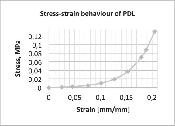
Nonlinear properties of the periodontal ligament.
Construction of the Model
CAD model
The CAD model of the tooth was obtained from three-dimensional (3D) scanning digitalization of an upper right human canine.
The CAD geometry of bone, PDL, attachments, and aligner was constructed, using a top-down assembly feature of SolidWorks® software, from the CAD model of the tooth, as shown in Figure 2. The aligner segment was modeled following the tooth anatomy, with an average thickness of 0.3 mm. The average thickness of the modeled PDL was 0.2 mm. Subsequently the CAD assembly was imported to ANSYS 14.5® FE software.
Figure 2. .
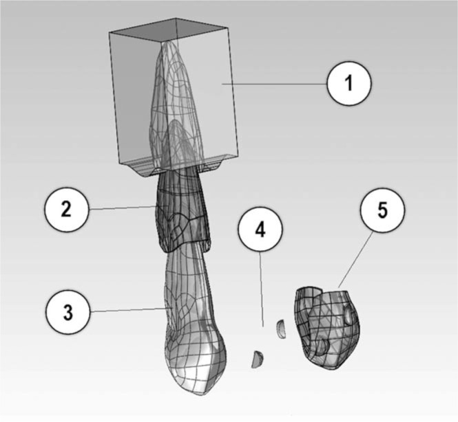
CAD model assembly: (1) Alveolar bone, (2) Periodontal ligament, (3) Tooth, (4) Composite attachments, and (5) Plastic aligner.
Meshing
The model meshing was constructed with tetrahedral elements. The number of nodes and elements for each component of the model are shown in Table 2.
Table 2. .
Number of Nodes and Elements of the Components of the Finite Element Model
Contact conditions
A rigid union condition without relative displacement (bonded) was established in ANSYS 14.5® in the following interfaces: ligament-bone, tooth-ligament, and tooth-attachments. A Coulomb friction condition was established in contact interfaces between the aligner and tooth crown surface and attachments, with a friction coefficient of μ = 0.2, similar to values reported by Ramalho and Vale17 in an in vitro wear test for enamel against composite.17
Boundary Conditions and Restrictions
A fixed support condition was established at the bone base, away from the areas of interaction between the surrounding bone and the tooth.
Simulation of tooth movement
For coherent FE simulation of the effect of one of the treatment stages with plastic aligners on an individual tooth, one must consider a sequential difference between the FE model and the clinical setting.
In a clinical setting, for effective aligner-based tooth movement a predetermined mismatch between the tooth and the aligner (in this case, a distal bodily movement of the canine) would be “programed” in the plastic aligner, which is subsequently positioned actively on the dental arch, initiating the force system that produces the desired tooth movement, strictly limited to the preset mismatch.
In this FE simulation of a clinical event, a displacement of 0.15 mm in the distal direction was imposed on the simulated thermoplastic aligner segment that was previously incorporated passively on the tooth crown (Figure 3).
Figure 3. .
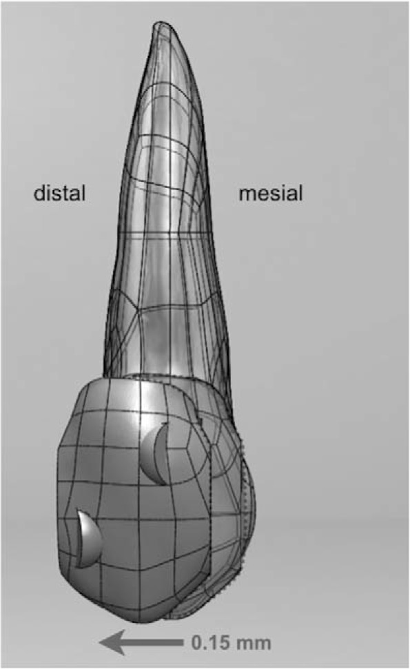
The effect of one treatment stage (aligner) was simulated by distally displacing the aligner segment 0.15 mm in the FE model.
RESULTS
The 3DFE model showed the following:
Tension-compression patterns at the PDL, in the model without composite attachments: (a) Two localized compression areas (blue in Figure 4a) in disto-cervical and meso-apical areas. (b) Two localized tension areas (red in Figure 4a) in meso-cervical and disto-apical areas.
Tension-compression patterns at the PDL with composite attachments: (a) A broad compression area (blue in Figure 4b) in all distal surfaces. (b) A broad tension area (red in Figure 4b) in all mesial surface.
Displacement patterns without composite attachments: The displacement of the model without attachments was equivalent to typical uncontrolled distal crown tipping (Figure 5a).
Displacement pattern with composite attachments: The displacement of the model with attachments was equivalent to typical distal bodily movement, as shown in Figure 5b.
Figure 4. .

(a) Tension-compression patterns at PDL, in a model without composite attachments. (b) Tension-compression patterns at PDL, in a model with composite attachments.
Figure 5. .
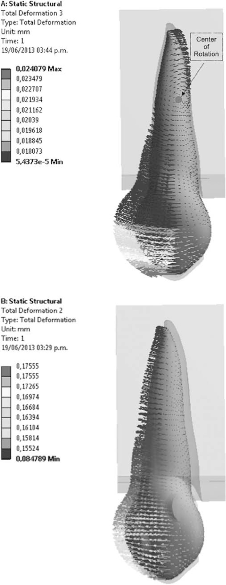
(a) Displacement patterns at the PDL in a model without composite attachments. (b) Displacement patterns at the PDL in a model without composite attachments.
DISCUSSION
The results of this study validate the proposal that composite attachments help generate a force system that approximates bodily movement of the studied tooth. When the aligner segment is displaced distally without attachments, a clockwise moment and distal inclination are produced on the tooth. The presence of composite attachments helps counteract this inclination, producing a counter-moment that in turn favors a bodily movement of the canine. The magnitude of this counter-moment is dependent on the amount of displacement imposed on the aligner segment and is produced by a complex force system that includes forces on the active surfaces of the attachments. Supporting this concept, compression zones (Figure 6) were observed at the active surface of attachments (mesial aspect of the gingival attachment and distal aspect of the incisal attachment).
Figure 6. .
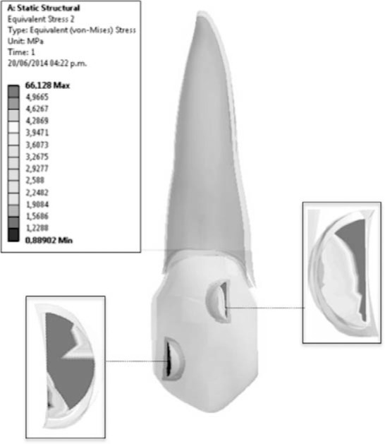
Equivalent stress patterns produced by aligner on active surfaces of attachments.
According to the model, the force system produced on the canine as a result of displacement imposed on the aligner consists of a 2.8-N (286-g) net force in the distal direction and a 30-N × mm (3062-g × mm) counterclockwise net moment (Figure 7). Both magnitudes are considered acceptable in the current clinical setting, generating a moment to force ratio of 10.7:1, in the optimal range reported by Cattaneo et al.18 It is important to acknowledge that the net moment is the result of the sum of moments generated in the whole system, including the moment produced by forces on the active surfaces of the attachments, which is of particular relevance to the present study.
Figure 7. .
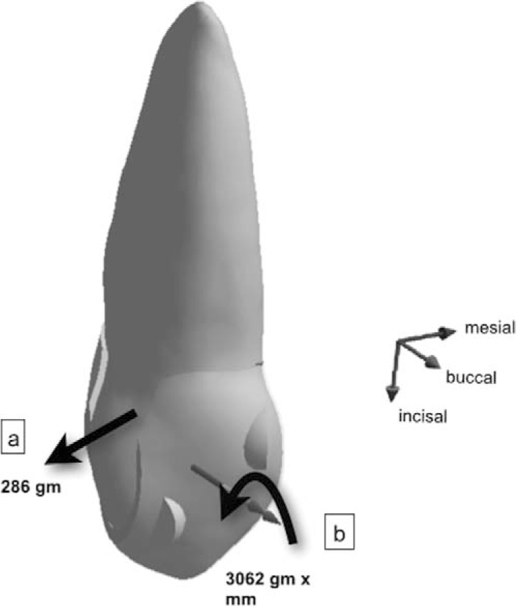
Resultant force system acting on the tooth; 286 g net force (a) in distal direction, 3062 g × mm net counterclockwise moment (b).
Reinforcing the previous reasoning, the absence of composite attachments (and, consequently, the absence of the counterclockwise moment they help produce) in the same type of aligner movement generates a tipping movement (clockwise rotation) in which the center of rotation is located approximately between the middle and apical thirds of the root, as seen in Figure 5a.
Concurring with the objectives of the present study, this basic, single-tooth model permits an initial exploration of poorly understood aligner-based force systems, grounded on simplified inferences. Supported by this work, the inclusion of additional dental units in future FE models will permit the analysis of the complex interaction of forces between multiple teeth and the aligner that acts upon them simultaneously.
An unexpected finding with this model was a marked tendency of “flaring” of the buccal and palatal flanks of the aligner segment during distal displacement (Figure 8). This finding is interesting because it could suggest an intrusive effect on the tooth and/or an expulsive tendency of the aligner during its function. Because of the important clinical implications of both tendencies, attention to these findings in future studies is recommended.
Figure 8. .
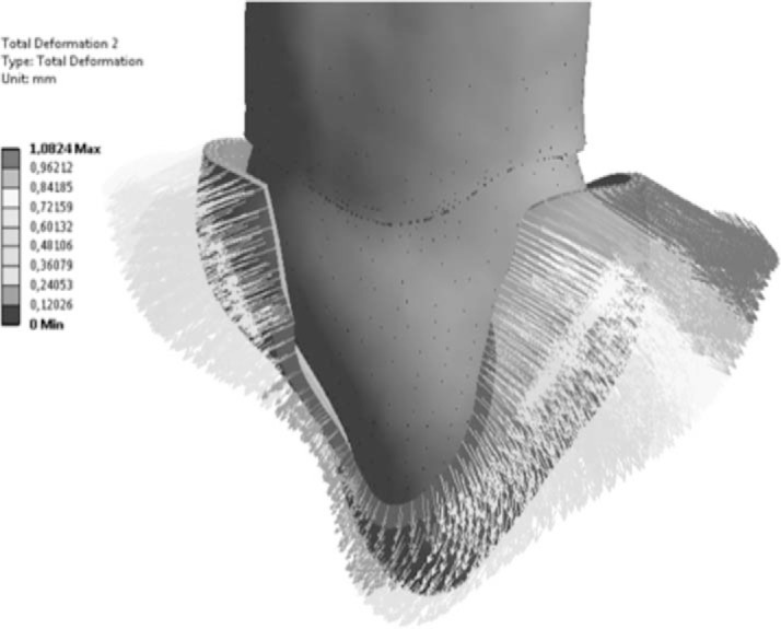
Bucco-lingual flaring of the aligner segment during distal displacement.
Recommendations
This study offers valuable information from the theoretical point of view, but its findings must be clinically validated to support the new systems of plastic aligners with more solid evidence. One of the limitations of the current FE model lies in the difficulty associated with simulating the large displacements on the tooth as a result of the long-term application of orthodontic forces. This occurs because such effects depend on biological events (resorption-apposition) present in variable time frames. The ability to simulate these events has not yet been incorporated into FE simulation models. The possibility of developing this application to current FE models should be explored.
The experience obtained with the present “one-tooth” FE model suggests that a complete model of the dental arch would enable the exploration of the complex interaction of forces generated during simultaneous movement of multiple dental units, allowing for a better understanding of the clinical performance within different systems of orthodontic therapy.
CONCLUSIONS
In a 3D FE model, the force system resulting from imposing a distal displacement on a plastic aligner segment incorporated onto an upper canine with composite attachments closely resembles bodily tooth movement.
The absence of composite attachments in the simulation of the same displacement produced a force system compatible with uncontrolled tooth inclination.
REFERENCES
- 1.Hayashia K, Araki Y, Uechi J, Hiroki Ohno H, Mizoguchi I. A novel method for the three-dimensional (3-D) analysis of orthodontic tooth movement calculation of rotation about and translation along the finite helical axis. J Biomech. 2002;35:45–51. doi: 10.1016/s0021-9290(01)00166-x. [DOI] [PubMed] [Google Scholar]
- 2.Jones ML, Hickman J, Middleton J, Knox J, Volp C. A validated finite element method study of orthodontic tooth movement in the human subject. J Orthod. 2001;28:29–38. doi: 10.1093/ortho/28.1.29. [DOI] [PubMed] [Google Scholar]
- 3.Cattaneo PM, Dalstra M, Melsen B. The finite element method: a tool to study orthodontic tooth movement. J Dent Res. 2005;84:428–433. doi: 10.1177/154405910508400506. [DOI] [PubMed] [Google Scholar]
- 4.McGuinness BN, Wilson AN, Jones M, Middleton J, Robertson NR. Stresses induced by edgewise appliances in the periodontal ligament—a finite element study. Angle Orthod. 1992;62:15–22. doi: 10.1043/0003-3219(1992)062<0015:SIBEAI>2.0.CO;2. [DOI] [PubMed] [Google Scholar]
- 5.Kusy RP. Influence of force systems on archwire-bracket combinations. Am J Orthod Dentofacial Orthop. 2005;127:333–342. doi: 10.1016/j.ajodo.2004.07.037. [DOI] [PubMed] [Google Scholar]
- 6.Smith RJ, Burstone CJ. Mechanics of tooth movement. Am J Orthod Dentofacial Orthop. 1984;85:294–307. doi: 10.1016/0002-9416(84)90187-8. [DOI] [PubMed] [Google Scholar]
- 7.Geramy A. Bodily labializing lateral incisors: 3D analysis using finite element method. Acta Odontol Scand. 2013;71:570–576. doi: 10.3109/00016357.2012.700059. [DOI] [PubMed] [Google Scholar]
- 8.Tominaga JY, Chiang PC, Ozaki H, et al. Effect of play between bracket and archwire on anterior tooth movement in sliding mechanics: a three-dimensional finite element study. J Dent Biomech. 2012;3 doi: 10.1177/1758736012461269. 1758736012461269. [DOI] [PMC free article] [PubMed] [Google Scholar]
- 9.Qian Y, Fan Y, Liu Z, Zhang M. Numerical simulation of tooth movement in a therapy period. Clin Biomech (Bristol Avon) 2008;23(suppl 1):S48–S52. doi: 10.1016/j.clinbiomech.2007.08.023. Epub 2007 Oct 17. [DOI] [PubMed] [Google Scholar]
- 10.Kravitz ND, Kusnoto B, BeGole E, Obrez A, Agran B. How well does Invisalign work? A prospective clinical study evaluating the efficacy of tooth movement with Invisalign. Am J Orthod Dentofacial Orthop. 2009;135:27–35. doi: 10.1016/j.ajodo.2007.05.018. [DOI] [PubMed] [Google Scholar]
- 11.Hahn W, Engelke B, Jung K, et al. Initial forces and moments delivered by removable thermoplastic appliances during rotation of an upper central incisor. Angle Orthod. 2010;80:239–246. doi: 10.2319/033009-181.1. [DOI] [PMC free article] [PubMed] [Google Scholar]
- 12.Hahn W, Zapf A, Dathe H, et al. Torquing an upper central incisor with aligners—acting forces and biomechanical principles. Eur J Orthod. 2010;32:607–613. doi: 10.1093/ejo/cjq007. [DOI] [PubMed] [Google Scholar]
- 13.Liang W, Rong Q, Lin J, Xu B. Torque control of the maxillary incisors in lingual and labial orthodontics: a 3-dimensional finite element analysis. Am J Orthod Dentofacial Orthop. 2009;135:316–322. doi: 10.1016/j.ajodo.2007.03.039. [DOI] [PubMed] [Google Scholar]
- 14. Filtek™ P60 Posterior Restorative Material—Mechanical Properties (n.d.). MatWeb online. Available at: http://www.matweb.com/search/datasheet.aspx?matguid=296bb60009ce4284a72b7771a6569bb1&ckck=1 Accessed March 2014. [Google Scholar]
- 15.Toms SR, Eberhardt AW. A nonlinear finite element analysis of the periodontal ligament under orthodontic tooth loading. Am J Orthod Dentofacial Orthop. 2003;123:657–665. doi: 10.1016/s0889-5406(03)00164-1. [DOI] [PubMed] [Google Scholar]
- 16.Osswald TA, Menges G. Materials Science of Polymers for Engineers 2nd ed. Kempton, Germany: Honser Publishing; 2003. p. 391. [Google Scholar]
- 17.Ramalho A, Vale Antunes P. Reciprocating wear test of dental composites against human teeth and glass. Wear. 2007;263:1095–1104. [Google Scholar]
- 18.Cattaneo PM, Dalstra M, Melsen B. Moment-to-force ratio, center of rotation, and force level: a finite element study predicting their interdependency for simulated orthodontic loading regimens. Am J Orthod Dentofacial Orthop. 2008;133:681–689. doi: 10.1016/j.ajodo.2006.05.038. [DOI] [PubMed] [Google Scholar]


