Abstract
Objective:
To evaluate the immediate effects of rapid maxillary expansion (RME) on the transverse skeletal and dentoalveolar changes with bone-borne (C-expander) and tooth-borne type expanders using cone-beam computed tomography (CBCT) in late adolescents.
Materials and Methods:
A sample of 28 female late-adolescent patients was divided into two groups according to the type of expander: bone-borne (C-expander, n = 15, age = 18.1 ± 4.4 years) and tooth-borne (hyrax, bands on premolars and molars, n = 13, age = 17.4 ± 3.4 years). CBCT scans were taken at 0.2-mm voxel size before treatment (T1) and 3 months after RME (T2). Transverse skeletal and dental expansion, alveolar inclination, tooth axis, vertical height of tooth, and buccal dehiscence were evaluated on maxillary premolars and molars. Paired t-test, independent t-test, one-way analysis of variance, and Scheffé post hoc analysis were performed.
Results:
The C-expander group produced greater skeletal expansion, except in the region of the first premolar (P < .05 or < .01), which showed slight buccal tipping of the alveolar bone. The Hyrax group had more buccal tipping of the alveolar bone and the tooth axes, except in the region of the second molar (P < .05 or < .01 or < .001). Dental expansion at the apex level was similar in the banded teeth (the first premolar and the first molar). Vertical height changes were apparent on the second premolar in the hyrax group (P < .05 or < .01). Significant buccal dehiscence occurred at the first premolar in the hyrax group (P < .01 or < .001). There were no significant differences between tooth types for any variables in the C-expander group.
Conclusions:
For patients in late adolescence, bone-borne expanders produced greater orthopedic effects and fewer dentoalveolar side effects compared to the hyrax expanders.
Keywords: Rapid maxillary expansion, Hyrax expander, Bone-borne expander, Cone-beam computed tomogram, C-implant, Alveolar bone
INTRODUCTION
Transverse maxillary deficiency is a common orthodontic problem and is often accompanied by unilateral or bilateral posterior crossbite and crowding.1 The best treatment timing to correct a transverse discrepancy of the maxilla is critical because growth in the transverse dimension typically precedes antero-posterior or vertical growth.2 Rapid maxillary expansion (RME) has been a widely accepted and well-established method for children with constricted maxillary arches, and correction is recommended before the peak in skeletal growth.3
The most common design of RME is a tooth-anchored expander with or without an acrylic plate.4,5 Common undesirable results in conventional RME are limited skeletal movement, dentoalveolar tipping, root resorption, detrimental periodontal effects such as dehiscence, and lack of long-term stablility.4–7 To moderate these side effects, clinicians have utilized bone-borne expanders, supported by the use of temporary skeletal anchorage devices (TSADs).8–11
There have been a few reports about the treatment effects of bone-borne expanders. A case report10 applied a combined design incorporating miniscrews placed in the paramedian area with bands on the teeth showed a successful treatment outcome. On the other hand, Lagravère et al.11 reported that there was no significant difference between bone-borne and tooth-borne RME. They used two onplants on the posterior region and a different expansion protocol and expansion screw design, compared with that used in the conventional RME group. Three-dimensional (3D) finite-element analysis study demonstrated that different designs of bone-borne expanders with microimplants had different characteristics of stress distribution.12–14 For example, a TSAD-supported hybrid hyrax showed the most transverse expansion, whereas TSADs on the palatal slope showed minimal rotational movement of the dentoalveolar unit.12 Inconsistent protocols among the studies, especially with regard to the design of the bone-borne expander and the period of time between comparisons, make clinically useful conclusions difficult.
Orthodontists have increased their use of cone-beam computed tomography (CBCT). This technology has been used for quantitative analyses of RME effects.5,7,11 Previous studies6,15 using two-dimensional cephalometric radiographs or dental models provide imprecise identification of dentoskeletal structures and limited information about skeletal changes in the maxillary region. CBCT images with adequate resolution can offer accurate evaluation of a target area with no distortion or overlapping.16 The purpose of this study is to evaluate and compare, in late adolescence, the immediate skeletal and dental effects after RME with bone-borne or tooth-borne type expanders using high-resolution CBCT.
MATERIALS AND METHODS
Subjects
The subjects consisted of 28 female adolescent patients. They were divided into two groups according to the type of RME used: bone-borne (group 1, C-expander, n = 15, age = 18.1 ± 4.4 years) and tooth-borne (group 2, hyrax, n = 13, age = 17.4 ± 3.4 years). The inclusion criteria for sampling were as follows: The initial CBCT shows an almost or completely closed midpalatal suture (suture area less than 2 mm2), a transverse maxillary deficiency with unilateral or bilateral posterior crossbite, permanent dentition including second molar eruption, >7 mm of activation, and no surgical or other treatment that might influence the RME outcome during the expansion period. This retrospective study was performed under approval from the Institutional Review Board of Kyung Hee University, Dental Hospital (IRB number: IRB-1312-01).
RME Design and Activation Protocol
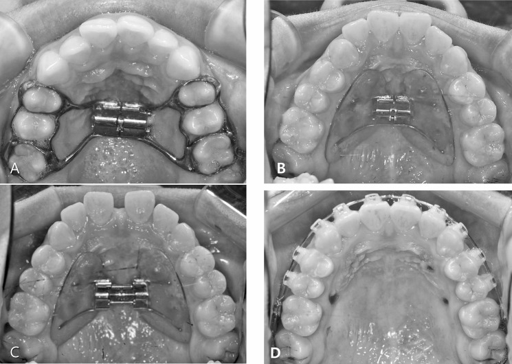
The tooth-borne expander used in our study was the hyrax type with bands on the first premolars and the first molars (Figure 1A). Buccal and lingual stainless steel bars of 1.0-mm diameter were used to stabilize the posterior dental segment. The bone-borne type was the C-expander (Figure 1B–D), supported with four TSADs (Cimplant Co, Seoul, Korea) of 1.8-mm diameter and 8.5-mm length and placed 8 mm beneath the alveolar ridge on the palatal slope: two between the canines and first premolars and two between the second premolars and first molars. The TSADs were connected to the expander through the hole of an acrylic resin cover. The 10-mm palate split-screw (Forestadent Co, Pforzheim, Germany) was activated over 7 mm after placement, followed by one-quarter turn per day (0.25-mm widening).
Figure 1.
Expander design used in the study: tooth-borne (A) and bone-borne (B). Intraoral photos after expansion (C) and 1 week after removal of C-expander in bone-borne group (D).
CBCT Protocol
CBCT scans were taken with a 0.2-mm voxel size level before treatment (T1) and 3 months after activation (T2) (group 1, Implagraphy, Vatech, Seoul, Korea; 12 × 9-cm FOV, 90 kV, 4.0-mA tube current, and 24-second scan time; group 2, Alphad vega, Asahi Roentgen, Kyoto, Japan: 10 mA, 80 kV, and 30-second scan time). The obtained data were analyzed by InVivoDental (Anatomage, San Jose, Calif). To set an identical reference plane in the T1 and T2 stages, the CBCT images were oriented along the palatal suture (x-plane), parallel to the palatal plane (y-plane) and tangent to the nasal floor (z-plane) (Figure 2). Transverse skeletal expansion was evaluated at the suture and with linear measurements at three different levels: nasal floor, hard palate, and hard palate below 5 mm. Transverse dental expansion was measured at the tooth apex and crown level (Figure 3). Alveolar inclination, tooth axis, vertical height of tooth, and buccal dehiscence on both sides were evaluated (Figures 4 and 5). All measurements were performed on each maxillary premolar and molar area. It was impossible to measure the data using blind methods because the appliance was inevitably shown in the CBCT images.
Figure 2.
Reorientation of CBCT scans: reoriented as perpendicular to midpalatal suture (axial section, x-plane), parallel to palatal plane (sagittal section, y-plane), and tangent to nasal floor at its most inferior level, where both of the palatal roots of the maxillary first molars are shown (coronal section, z-plane).
Figure 3.
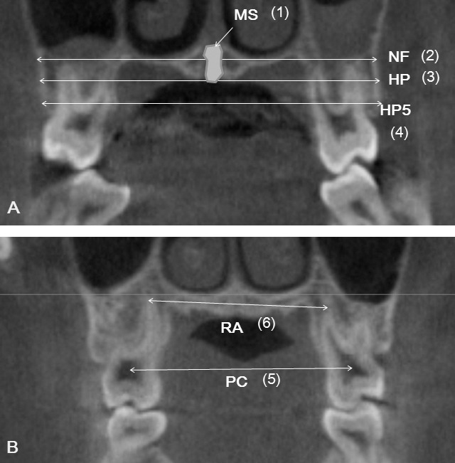
Definition of measurements. Skeletal (A) and dental (B) transverse distances. NF indicates maxillary width tangent to the nasal floor at its most inferior level; HP, maxillary width tangent to the hard palate at the most inferior level; HP5, maxillary width parallel to the line NF and 5 mm below the line HP; MS, area of midpalatal suture; RA, distance between palatal root apices; and PC, distance between pulp chambers.
Figure 4.

Alveolar bone inclination (A) (between the palatal alveolar slop and NF. Alr, right side; All, left side) and tooth inclination (B) (between the palatal root axis and NF. Tor, right side; Tol, left side).
Figure 5.

(A) Vertical dental heights from NF to mesiobuccal cusp (Br, right side; Bl, left side) or mesiopalatal cusp (Pr, right side; Pl, left side); (B) Alveolar bone dehiscence measured from the cemento-enamel junction (CEJ) to the alveolar crest on buccal side. Crr indicates right side; Crl, left side.
Statistical Analysis
Normality of the data distribution was confirmed using the Shapiro-Wilk test. All of the measurements were repeated by the same operator after 2 weeks. The difference ranged from 0.23 mm to 0.35 mm for linear measurements, from 0.35° to 0.42° for angular measurements, and from 0.37 mm2 to 0.45 mm2 for area measurements, according to Dahlberg's formula. The mean of the two measurements was used for this study. A paired t-test was done for comparison between the T1 and T2 stages in each group, and an independent t-test was performed for comparison of the mean differences between the two groups. One-way analysis of variance (ANOVA) and Scheffé post hoc analysis were performed for comparison between tooth types in each group. A P-value of <.05 was considered to indicate a statistically significant difference.
RESULTS
Comparison Between Tooth-Borne and Bone-Borne Expanders (Figure 6 and Table 1)
Figure 6.
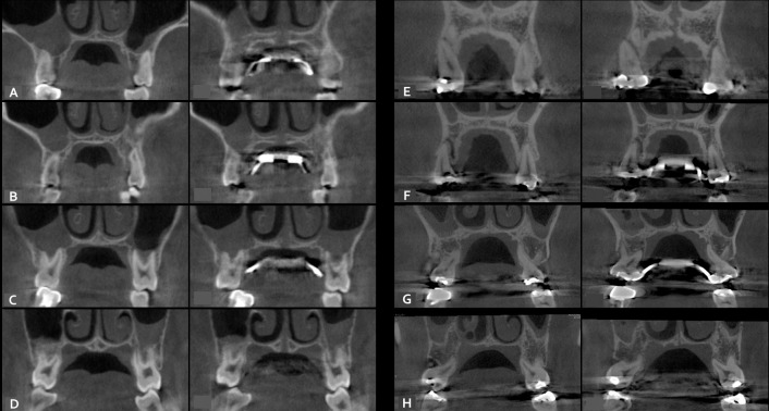
The examples of rapid maxillary expansion with bone-borne (A–D) and tooth-borne (E–H) expanders, compared between pretreatment period and after expansion at the first premolar (A and E), the second premolar (B and F), the first molar (C and G), and the second molar (D and H).
Table 1.
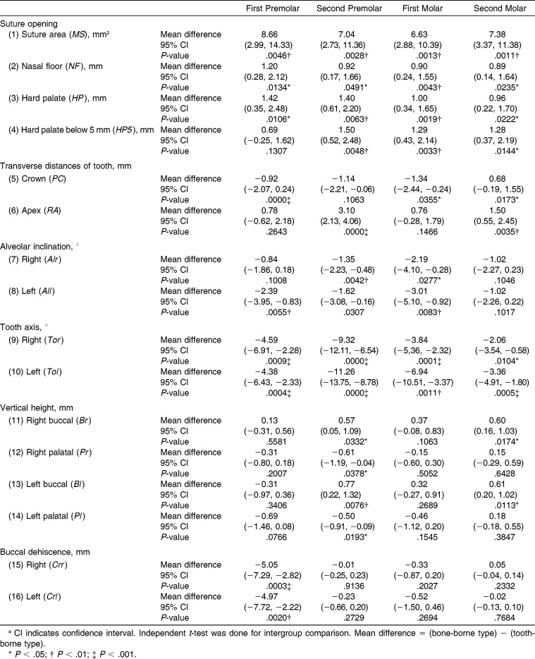
Comparison of the Immediate Changes After Rapid Maxillary Expansion Between Bone-Borne (Group 1) and Tooth-Borne (Group 2) According to the Tooth Typea
Skeletal changes
The midpalatal sutures were successfully opened both in hyrax and C-expander groups in a triangular pattern, with the least increase at the nasal floor and the greatest increase at the hard palate below 5 mm (P < .001). There was less expansion at the skeletal than at the dental level. The C-expander group showed greater statistically significant increases in the suture expansion than did the hyrax group, except for the linear measurements in the first premolar region (P < .05 or < .01).
Dentoalveolar changes
Angular changes of the alveolus and tooth axes were apparent in both groups. The hyrax group showed more buccal tipping of the tooth axes than did the C-expander group in all areas (P < .01 or < .001). Alveolar bending was more pronounced in the hyrax group, except in the second molar region (P < .05 or < .01). Transverse dental expansion at the dental apices was similar in both groups at the first premolar and the first molar; however, less dental expansion occurred in the hyrax group at the second premolar and the second molar. At the crown level, expansion was similar between the groups only at the second premolar. The hyrax group produced more crown expansion at the first premolar and the first molar, and the C-expander produced more at the second molar. There was no difference between the groups in terms of vertical change at the first premolar and the first molar. Intrusion of the buccal cusp and extrusion of the palatal cusp in the second premolar region was more apparent in the hyrax group than in the C-expander group (P < .05 or < .01). In the second molar area there was a statistical difference only in the amount of intrusion of the buccal cusp (P < .05). There was no significant difference in the amount of vertical alveolar bone loss between groups, except that buccal dehiscence at the first premolar was obvious in the hyrax group (P < .01 or < .001).
Comparison Between Molars and Premolars in Each Expander (Table 2)
Table 2.
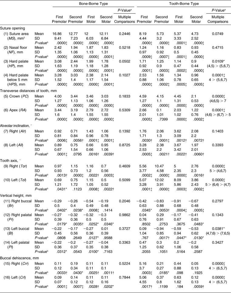
The Immediate Changes After Rapid Maxillary Expansion With Bone-Borne or Tooth-Borne Appliance and the Comparison Results According to the Tooth Type in Each Group
Table 2.
Continued.
In the C-expander group, there were no significant differences between molars and premolars in any of the skeletal or dentoalveolar variables. In the hyrax group, the amount of skeletal transverse expansion at the hard palate 5 mm below to the hard palate at the most inferior level was significantly increased at the first premolar compared with other regions (P < .001). Buccal tipping of the tooth axis was the most apparent at the second premolar (P < .001). The amount of dental expansion at the crown level was significantly less at the second molar area (P < .001); meanwhile, more expansion at the apex level was observed in the first premolar and the first molar area (P < .001). Vertical alveolar bone loss was significantly increased at the first premolar area compared with other posterior teeth (P < .001).
DISCUSSION
The subjects recruited into our study were late adolescents, which is a bit older, given the general perception that the predictability of orthopedic expansion is greatly decreased after 15 years of age.3 The CBCT T1 images showed an almost or completely closed midpalatal suture. However, many studies have shown that the obliteration of the midpalatal suture in x-rays does not correlate with chronologic age,17,18 and nearly identical histological results are shown in individuals aged 10 to 30 years.19 In our study, skeletal transverse expansion was achieved with the tooth-borne RME group, although much less than was observed with the bone-borne group. The resistance to expansion at the suture is only one consideration when evaluating RME. One must also consider the influence of the zygomatic buttress and the pterygopalatine junction as well as subsequent relapse.20
With regard to the maxillary transverse dimension, the bone-borne expander group increased almost twice as much at the skeletal level than did the hyrax group (except in the first premolar area). In agreement with previous studies,21,22 the skeletal expansion pattern in the hyrax group was triangular, with a wider base at the anterior portion of maxilla, whereas the pattern was rather parallel in the bone-borne expander group. This explains the similar amount of expansion between the two groups in the first premolar area. Weissheimer et al.5 reported that the immediate skeletal gain at the hard palate level after conventional RME (hyrax) treatment accounted for approximately 54.7% of the dental crown expansion in the anterior region and for 39.2% in the posterior region. In our study, the C-expander group showed skeletal gain of about 57.5% to 77.0% of the dental crown expansion, whereas the hyrax group showed a skeletal gain of 25.6% to 42.9%.
Unlike the skeletal effects, dental expansion differed at the molar area compared to the premolar area, regardless of whether the molars were banded. No significant differences between the groups were found at the apex of the first premolar or the first molar; however, less expansion was observed at the crowns in the C-expander group. At the second premolar in the hyrax group, which was not banded, the expansion amount at the root apex was almost negligible, whereas with the C-expander group, crown and apex expansion were similar. At the second molar, more expansion was apparent in the C-expander group at both the crown and apex level. The expansion pattern of the buccal sections with this device was close to parallel. In the hyrax group, the rigidity of the appliance resisted the buccal tipping of the banded teeth, resulting in significant expansion of the apex. While both the first premolar and the first molar were banded, the direction of the force is located anterior to the center of resistance of each maxillary half, and the RME flexes in response to the resistance value difference between molar and premolar areas.23
Alveolar bending is inevitable with RME because the maxillary two halves are rotated, with the expansion vector centered on the frontonasal suture in the coronal plane.21,24 Weissheimer et al.5 reported that the expansion at the alveolar level accounted for 70% of the total expansion, 36% of which represents sutural expansion and 34% of which is purely alveolar bending toward the buccal aspect. In our study, the amount of alveolar bone bending in the hyrax group was more than twice that observed in the C-expander group. The ratio of dental tipping to alveolar bone bending (except at the second molar) was 0.92 to 1.30 in the C-expander group, which represents a negligible change of tooth axis in the alveolar housing during expansion. On the other hand, the hyrax appliance produced a greater buccal inclination of the posterior teeth that exceeded the amount of alveolar bending. The amount of dental tipping was 1.8 to 5.1 times that of the alveolar bending. In the hyrax group there was a significant difference of buccal inclination between the molar and the premolar. The unbanded second premolar tipped buccally almost twice as much as the banded teeth, which is in accordance with the findings of Garib et al.24 The second premolar showed controlled tipping without any expansion at the apex level because the force was applied by the lingual bar, which was located far from the center of resistance. This simple force on the crown generates a buccal tipping moment, whereas more bodily movement was obtained on the banded teeth.25 The angular change of tooth axis between the left and right sides in the hyrax group showed a difference of less than 3°, and this difference was even more insignificant in the C-expander group, which suggested symmetrical expansion.
The expansion force delivered during RME produces compression of the periodontal ligament on the buccal surfaces of the supporting teeth. Garib et al.26 reported that RME reduced the buccal bone plate thickness of supporting teeth 0.6 to 0.9 mm and increased the lingual bone plate thickness 0.8 to 1.3 mm. Bone dehiscences were induced on the buccal aspect of the anchor teeth (7.1 ± 4.6 mm at the first premolars and 3.8 ± 4.4 mm at the mesiobuccal area of the first molars), especially in subjects. These results confirmed the presence of significant vertical alveolar bone loss at the first premolar area in the hyrax group, which was associated with more dental expansion relative to the skeletal expansion. Although there was statistically significant vertical bone loss in the C-expander group, the real amount of loss was less than 0.3 mm, which was not clinically important.
The only clinical trial study11 that compares bone-anchored to conventional RME reports that both appliances provided similar outcomes. No difference was found in the apical expansion of the molars. More expansion at the crown level of the first premolar was shown in the conventional RME group. However, they did not evaluate the skeletal level above the root apex for transverse expansion, and they did not differentiate between alveolar bending and tipping of the teeth axes. Furthermore, discordant results can be caused by the use of different designs of bone-borne expanders. Variation in design, such as that associated with the anchorage site, the stress distribution, and the expansion pattern of the bone-anchored-RME, will make a difference in the outcome. In the study of Lagravère et al.,11 two implants were positioned on the palatal slope between the second premolar and the first molar area, which concentrated the force on the posterior region. In our study, the C-expander was supported by four implants, two placed between the canine and the first premolar and two between the second premolar and the first molar area, providing a force distribution similar to that of the four-point hyrax appliance. Use of the acrylic plate distributed the stress throughout the palate, decreasing the concentration of the stress around the implants. A 3D finite-element analysis revealed parallel expansion of the midpalatal suture and negligible dental tipping using the C-expander, in accordance with the results of our study.12
CONCLUSIONS
In late-adolescent patients, bone-borne expanders produced greater transverse skeletal expansion when compared to tooth-borne hyrax expanders.
In the bone-borne expander group there was less alveolar bending, less dental tipping, and less vertical alveolar bone loss at the first premolar.
Dental expansion at the root apices in the C-expander group was similar to that of the banded teeth of the hyrax group but greater than that of the nonbanded teeth.
The bone-borne expander used without surgical assistance can be an effective treatment modality for maxillary skeletal deficiency in late adolescents.
ACKNOWLEDGMENT
This study is based in part on a research thesis completed at Kyung Hee University. This work was supported by the National Research Foundation of Korea (NRF), funded by the Korean government (MEST) (2012R1A5A2051388).
REFERENCES
- 1.Ramires T, Maia RA, Barone JR. Nasal cavity changes and the respiratory standard after maxillary expansion. Braz J Otorhinolaryngol. 2008;74:763–769. doi: 10.1016/S1808-8694(15)31388-4. [DOI] [PMC free article] [PubMed] [Google Scholar]
- 2.Bishara SE, Jakobsen JR, Treder J, Nowak A. Arch width changes from 6 weeks to 45 years of age. Am J Orthod Dentofacial Orthop. 1997;111:401–409. doi: 10.1016/s0889-5406(97)80022-4. [DOI] [PubMed] [Google Scholar]
- 3.Baccetti T, Franchi L, Cameron CG, McNamara JA., Jr Treatment timing for rapid maxillary expansion. Angle Orthod. 2001;71:343–350. doi: 10.1043/0003-3219(2001)071<0343:TTFRME>2.0.CO;2. [DOI] [PubMed] [Google Scholar]
- 4.Erverdi N, Okar I, Kucukkeles N, Arbak S. A comparison of two different rapid palatal expansion techniques from the point of root resorption. Am J Orthod Dentofacial Orthop. 1994;106:47–51. doi: 10.1016/S0889-5406(94)70020-6. [DOI] [PubMed] [Google Scholar]
- 5.Weissheimer A, de Menezes LM, Mezomo M, Dias DM, de Lima EM, Rizzatto SM. Immediate effects of rapid maxillary expansion with Haas-type and hyrax-type expanders: a randomized clinical trial. Am J Orthod Dentofacial Orthop. 2011;140:366–376. doi: 10.1016/j.ajodo.2010.07.025. [DOI] [PubMed] [Google Scholar]
- 6.Gurel HG, Memili B, Erkan M, Sukurica Y. Long-term effects of rapid maxillary expansion followed by fixed appliances. Angle Orthod. 2010;80:5–9. doi: 10.2319/011209-22.1. [DOI] [PMC free article] [PubMed] [Google Scholar]
- 7.Baysal A, Uysala T, Velia I, et al. Evaluation of alveolar bone loss following rapid maxillary expansion using cone-beam computed tomography. Korean J Orthod. 2013;43:83–95. doi: 10.4041/kjod.2013.43.2.83. [DOI] [PMC free article] [PubMed] [Google Scholar]
- 8.Winsauer H, Vlachojannis J, Winsauer C, Ludwig B, Walter A. A bone-borne appliance for rapid maxillary expansion. J Clin Orthod. 2013;47:375–381. [PubMed] [Google Scholar]
- 9.Wilmes B, Nienkemper M, Drescher D. Application and effectiveness of a mini-implant- and tooth-borne rapid palatal expansion device: the hybrid hyrax. World J Orthod. 2010;11:323–330. [PubMed] [Google Scholar]
- 10.Lee KJ, Park YC, Park JY, Hwang WS. Miniscrew-assisted nonsurgical palatal expansion before orthognathic surgery for a patient with severe mandibular prognathism. Am J Orthod Dentofacial Orthop. 2010;137:830–839. doi: 10.1016/j.ajodo.2007.10.065. [DOI] [PubMed] [Google Scholar]
- 11.Lagravère MO, Carey J, Heo G, Toogood RW, Major PW. Transverse, vertical, and anteroposterior changes from bone-anchored maxillary expansion vs traditional rapid maxillary expansion: a randomized clinical trial. Am J Orthod Dentofacial Orthop. 2010;137:304.e1–304.e12. doi: 10.1016/j.ajodo.2009.09.016. [DOI] [PubMed] [Google Scholar]
- 12.Lee HK, Bayome M, Ahn CS, et al. Stress distribution and displacement by different bone-borne palatal expanders with micro-implants: a three-dimensional finite-element analysis. Eur J Orthod. In press doi: 10.1093/ejo/cjs063. [DOI] [PubMed] [Google Scholar]
- 13.Lee SC, Park JH, Bayome M, Kim KB, Araujo EA, Kook YA. Effect of bone-borne rapid maxillary expanders with and without surgical assistance on the craniofacial structures using finite element analysis. Am J Orthod Dentofacial Orthop. 2014;145:638–648. doi: 10.1016/j.ajodo.2013.12.029. [DOI] [PubMed] [Google Scholar]
- 14.Ludwig B, Baumgaertel S, Zorkun B, et al. Application of a new viscoelastic finite element method model and analysis of miniscrew-supported hybrid hyrax treatment. Am J Orthod Dentofacial Orthop. 2013;143:426–435. doi: 10.1016/j.ajodo.2012.07.019. [DOI] [PubMed] [Google Scholar]
- 15.Handelman CS, Wang L, BeGole EA, Haas AJ. Nonsurgical rapid maxillary expansion in adults: report on 47 cases using the Haas expander. Angle Orthod. 2000;70:129–144. doi: 10.1043/0003-3219(2000)070<0129:NRMEIA>2.0.CO;2. [DOI] [PubMed] [Google Scholar]
- 16.Lagravère MO, Carey J, Toogood RW, Major PW. Three-dimensional accuracy of measurements made with software on cone-beam computed tomography images. Am J Orthod Dentofacial Orthop. 2008;134:112–116. doi: 10.1016/j.ajodo.2006.08.024. [DOI] [PubMed] [Google Scholar]
- 17.Persson M, Thilander B. Palatal suture closure in man from 15 to 35 years of age. Am J Orthod. 1977;72:42–52. doi: 10.1016/0002-9416(77)90123-3. [DOI] [PubMed] [Google Scholar]
- 18.Korbmacher H, Schilling A, Püschel K, Amling M, Kahl-Nieke B. Age-dependent three-dimensional microcomputed tomography analysis of the human midpalatal suture. J Orofac Orthop. 2007;68:364–376. doi: 10.1007/s00056-007-0729-7. [DOI] [PubMed] [Google Scholar]
- 19.Knaup B, Yildizhan F, Wehrbein H. Age-related changes in the midpalatal suture. A histomorphometric study. J Orofac Orthop. 2004;65:467–474. doi: 10.1007/s00056-004-0415-y. [DOI] [PubMed] [Google Scholar]
- 20.Bell WH, Epker BN. Surgical orthodontic expansion of the maxilla. Am J Orthod. 1976;70:517–528. doi: 10.1016/0002-9416(76)90276-1. [DOI] [PubMed] [Google Scholar]
- 21.Garrett BJ, Caruso JM, Rungcharassaeng K, Farrage JR, Kim JS, Taylor GD. Skeletal effects to the maxilla after rapid maxillary expansion assessed with cone-beam computed tomography. Am J Orthod Dentofacial Orthop. 2008;134:8.e1–8.e11. doi: 10.1016/j.ajodo.2008.06.004. [DOI] [PubMed] [Google Scholar]
- 22.Lione R, Ballanti F, Franchi L, Baccetti T, Cozza P. Treatment and posttreatment skeletal effects of rapid maxillary expansion studied with low-dose computed tomography in growing subjects. Am J Orthod Dentofacial Orthop. 2008;134:389–392. doi: 10.1016/j.ajodo.2008.05.011. [DOI] [PubMed] [Google Scholar]
- 23.Braun S, Bottrel JA, Lee KG, Lunazzi JJ, Legan HL. The biomechanics of rapid maxillary sutural expansion. Am J Orthod Dentofacial Orthop. 2000;118:257–261. doi: 10.1067/mod.2000.108254. [DOI] [PubMed] [Google Scholar]
- 24.Garib DG, Henriques JF, Janson G, Freitas MR, Coelho RA. Rapid maxillary expansion-tooth tissue-borne versus tooth-borne-expanders: a computed tomography evaluation of dentoskeletal effects. Angle Orthod. 2005;75:548–557. doi: 10.1043/0003-3219(2005)75[548:RMETVT]2.0.CO;2. [DOI] [PubMed] [Google Scholar]
- 25.Smith RJ, Burstone CJ. Mechanics of tooth movement. Am J Orthod. 1984;85:294–307. doi: 10.1016/0002-9416(84)90187-8. [DOI] [PubMed] [Google Scholar]
- 26.Garib DG, Henriques JF, Janson G, de Freitas MR, Fernandes AY. Periodontal effects of rapid maxillary expansion with tooth-tissue-borne and tooth-borne expanders: a computed tomography evaluation. Am J Orthod Dentofacial Orthop. 2006;129:749–758. doi: 10.1016/j.ajodo.2006.02.021. [DOI] [PubMed] [Google Scholar]


