Abstract
We report on efforts to improve the achievable spatial resolution in neutron imaging by centroiding the scintillation light from gadolinium oxysulfide scintillators. The current state-of-the-art neutron imaging spatial resolution is about 10 μm, and many applications of neutron imaging would benefit from at least an order of magnitude improvement in the spatial resolution. The detector scheme that we have developed magnifies the scintillation light from a gadolinium oxysulfide scintillator, calculates the center of mass of the scintillation event, resulting in an event-based imaging detector with spatial resolution of about 2 μm.
Keywords: Neutron imaging, Centroiding detector, Neutron time of flight, High resolution
1. Introduction
Neutron imaging methods continue to rapidly develop and to be applied in a wide array of research fields [1]. One aspect that has enabled neutron imaging to be more widely applied is the improvement in detector technology in terms of spatial and time resolution. Time resolution has two aspects. The first is directly related to the fluence rate and dictates the counting statistics of the image; that is the total exposure time. The other aspect is the ability to resolve the arrival time of a neutron from a pulsed neutron source, with timing resolution of at least 1 μs being required. The spatial resolution of most currently employed detector systems is primarily dictated by the range of the charged particle that results from the neutron capture reaction. In the case of gadolinium oxysulfide (GadOx) the range of the electrons and betas is about 5–10 μm (from Stopping and Range of Ions in Matter calculations [2]) so that the spatial resolution is 10–20 μm. Due to the high energy of the emitted alpha and triton, lithium-based scintillators have coarser resolution (~50 μm) although the light output typically is significantly greater than Gd-based materials. As well, more light is emitted in the Bragg peaks so that in order to improve the spatial resolution beyond the track of about 50 μm one must model the track shape. In neutron-sensitive microchannel plate (MCP) detectors, the spatial resolution is dictated by the charged particle range, micropore diameter, and bias angle with an ultimate spatial resolution of about 15 μm having been achieved in 2009 [3]. MCP systems have very high timing resolution (at least 750 ps) and are thus applicable to imaging at a pulsed source, but neutron sensitive MCP systems will not be able to significantly improve on the spatial resolution over the current state-of-the-art [3–6].
While a spatial resolution of ~15 μm is adequate for many applications, there are several high impact research areas that require finer spatial resolution. In particular, neutron imaging is the only technique that non-destructively measures the water content in an operating proton exchange membrane fuel cell (PEMFC). With a spatial resolution of 15 μm, neutron imaging can only measure the water concentration gradient in the 250 μm thick gas diffusion media of PEMFC and currently cannot provide detailed measures of the water content within an automotive-competitive membrane electrode assembly (MEA), which has a through-plane thickness of less than 50 μm.
There are a few efforts underway to improve neutron detectors with spatial resolution of about 1 μm. Tritk et al. developed an enriched Gd-157 GadOx scintillator that would have high stopping power with a thin scintillator to reduce the light blooming from scattering in the scintillator emulsion [7]. Since this method couples a custom lens to a charged coupled device (CCD), there is no possibility to apply it to pulsed neutron sources. Vavrik et al. coat ~1 μm thick coatings of LiF or B4C on Timepix-based detectors to look at light ion particle tracks, reporting resolution better than the Timepix pixel pitch, but the thin converter foils have low thermal neutron stopping power [8]. Song et al. report on simulation studies of a scintillation light track detector that is composed of ~1 μm diameter scintillator fibers interleaved with ~1 μm diameter capillaries. Their simulation shows resolution on the order of 1 μm with 3.7% stopping power [9]. There have been studies on photon event counting detectors with a primary application field of astronomy [10,11]. An imaging detector using a LiF scintillator coupled to an image intensifier was able to achieve 50 μm resolution but was strongly limited in event rate due to slow processing of image frames [12]. In this report, we present a proof-of-concept neutron detector system using a GadOx scintillator and describe the event center of mass algorithm that is based on many of these previous developments.
2. Experimental
The measurements were conducted at the NIST neutron imaging facility located at beam tube 2 (BT2) of the NIST Center for Neutron Research. BT2 has a thermal neutron spectrum and the ability to choose several collimation ratio settings (instrument length to beam-defining aperture size). For the work presented here, the beam-defining aperture was a 1 mm wide by 1 cm tall slit producing a neutron fluence rate of 7 × 105 cm−2 s−1 [13].
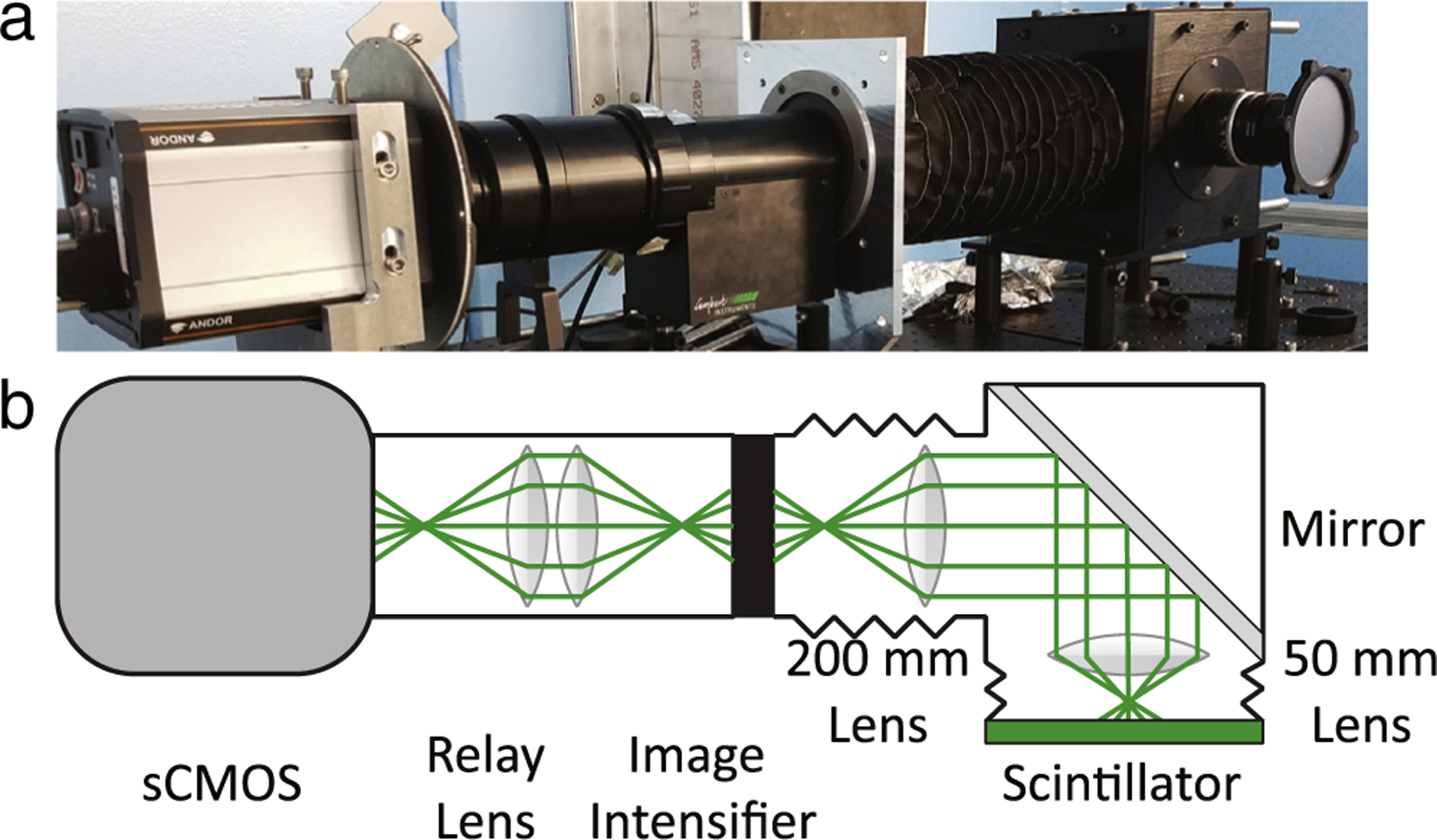
The detector is an intensified version of a macroscope [14]. A GadOx screen (P43 from Lexel Imaging) with areal mass density of 7.6 mg cm−2 (about 20 μm thickness) absorbs neutrons, and emits scintillation light with a peak wavelength of about 545 nm [15]. The light emission is proportional to the absorbed energy of the charged particles; for estimation purposes, the charged particles have on average 70 keV of energy which yields about 1000 photons emitted in all directions. The conversion electron spectrum has been measured, and there are two primary electron energy branches, centered at about 25 and 100 keV, for both Gd-157 and Gd-159, the two primary isotopes that account for neutron absorption in Gd [16].
As shown in Fig. 1 the macroscope is an optical, infinity corrected microscope that magnifies the image of the scintillation light. In the present design, a Nikon 50 mm f/1.2 lens serves as the objective lens, and a Nikon 200 mm f/4 lens serves as the ocular lens. A mirror at a 45° angle to the incident beam ensures that electronic components that are sensitive to radiation damage are kept out of the direct beam. The objective lens is placed about 46 mm from the scintillator screen. With a lens diameter of about 35 mm, the solid angle is about 2.3 steradian so that about 200 photons per neutron capture are focused onto the intensifier. Assuming a Gaussian distribution, one expects a centroiding algorithm to improve the spatial resolution by one order of magnitude for 100 photons; for a 10 μm spot size one would expect a resulting 1 μm spatial resolution [11].
Fig. 1.

Photo and layout sketch of the intensified macroscope.
A Lambert Instruments TRiCATT 25 GaAsP image intensifier (Hamamatsu microchannel plate with nominal 6 μm diameter channels) amplifies the scintillation photon signal by about 104. The image is transferred from the output phosphor screen of the intensifier to the camera by a 1:1 relay lens. The camera is an Andor NEO sCMOS cooled to −30 °C. With the magnification of 4, the field of view of the camera is about 4.1 × 3.5 mm, with effective pixel pitch of 1.625 μm. The field of view is sufficient to acquire information from two land/channel regions within a typical PEMFC test section. Three acquisition schemes were employed. In all, the camera was operated in 11-bit low noise mode. One data set employed a global shutter without pixel binning, the second (third) data set employed a rolling (global) shutter with 2 × 2 pixel binning. For the fluence rate employed, an exposure time of 3 ms was found to have events covering about 10% of the active area, so that there would be few overlapping events. Typical PEMFC measurements of the through-plane water content require an exposure time of about 20 min in order to reach liquid water thickness uncertainties of about 10 μm. Even though the spatial resolution is increased by a factor of 10, this effective exposure time was used as a guide for the number of frames to collect to obtain an image with reasonable counting statistics, which is about 4 × 10⁵ frames per condition. Depending on the readout mode employed and the size of the region of interest, individual frames could be read out at frame rates up to 150 Hz while capturing the active area of the PEMFC test section. At present time, the data acquisition system permitted saving frames directly to hard drive at only 70 Hz, so that a data set of 4 × 10⁵ frames can be acquired in about 95 min. Also, the after-glow of P43 is about 1.5 ms to 10 % and 20 ms to 0.01%, thus one frame is not greatly impacted by previous events [10]. As an aside, GadOx doped with praseodymium has a 7 μs decay time, providing suitable time resolution for spallation neutron sources.
For this demonstration, event reconstruction is performed in software, which also necessitates the storing of individual frames. The most time-consuming portion of the reconstruction is reducing noise in each frame. First, the instantaneous camera readout noise (which includes correcting for afterglow) is calculated by taking the median of 5 image frames centered on the frame of interest. A spatial median filter is then applied to both this offset and the frame of interest. The offset corrected image is binned with 2 × 2 binning (pixel values are averaged in the binning process) and subsequently spatially median filtered to improve event detection. This effectively blurs out any imaging of individual microchannel pores of the image intensifier. All pixels above a threshold are placed in a list (all below the threshold are set to zero), and each scintillation event is detected with the region growing algorithm of the Interactive Data Language (IDL), seeded by the next pixel in the list. Once a pixel is assigned to a scintillation event, it is removed from the list and set to zero for the region grow algorithm. In order to be considered valid, the scintillation event in the binned image must have an area and total number of gray values larger than a given threshold, a pixel area of at least 4 and total gray level value of at least 9. The center of mass for each scintillation event is then calculated from the pixels determined to be within the region. In other words, the centroiding algorithm is an all above threshold, center of gravity calculation with no windowing applied. On a DELL Precision T1650 desktop computer, for a frame size of 2560 × 700, the processing time is about 0.5 s, with about 0.3 s being devoted to the median filtering in time and space, 0.05 s loading the frame from disk into memory. As such, the optimization of the center of gravity calculation has not been pursued at this point.
3. Results
Two PEMFC test section were used in the reported measurements [17]. Both were aligned in the beam with an angular resolution of 0.001° by finding the angle at which the observed through plane thickness was a minimum using a spatial resolution of 20 μm. Since the width of the test section along the beam direction is about 2 cm, the uncertainty in alignment introduces an uncertainty of position of less than 0.2 μm. The test sections differed primarily in the flow field configuration, one was a parallel configuration, the other a serpentine configuration. The detector configuration for the serpentine channel was a global shutter, with no pixel binning. The detector configuration for the parallel flow field used a rolling and global shutter and 2 × 2 pixel binning, reducing the overall data size and the time to acquire 4 × 10⁵ frames.
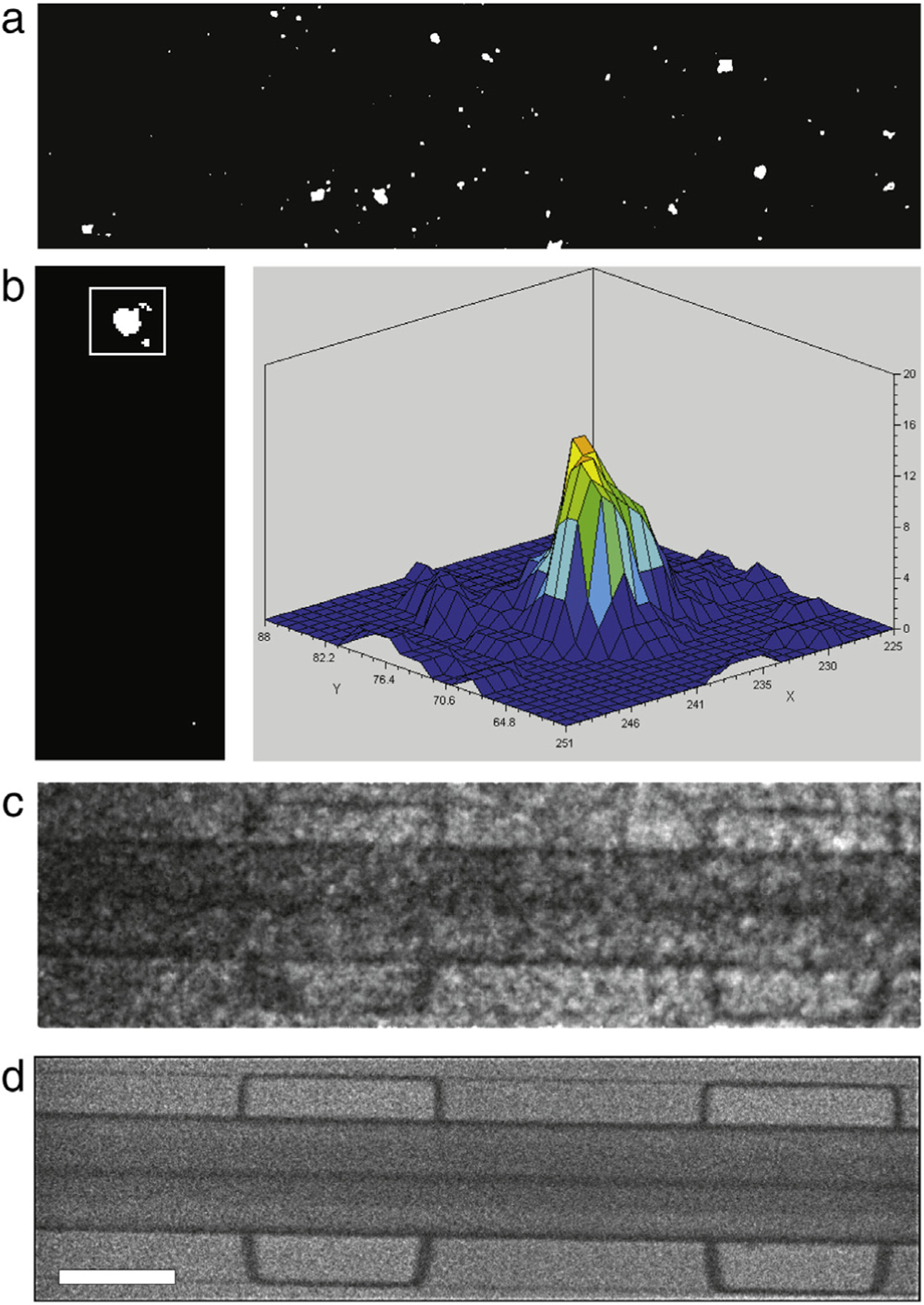
Shown in Fig. 2, are representative images from the image forming process. Shown in (a) is a binarized, single frame after threshold, shown in (b) is the spatial distribution of the captured light from one scintillation event, shown in (c) is the sum of 3000 frames from after the threshold is applied exhibiting 20 μm resolution, and (d) is the result of the centroiding algorithm from 80,000 frames exhibiting 2 μm resolution (see Fig. 4d). Due to the short exposure time of each frame and decay time of the scintillator, all pixels above the threshold are assumed to belong to the same scintillation event.
Fig. 2.

(a) Binarized frame after background subtraction, median filtering and rebinning. (b) Shape of a scintillation event. (c) Sum of 3000 frames after only thresholding is applied. (d) Centroided image from 80,000 frames, white scale bar length is 0.5 mm. In (a), (c), (d) the full height of the frame is 0.975 mm and the width is 3.51 mm.
Fig. 4.

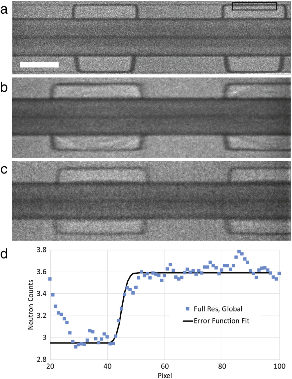
Image quality comparison between three acquisition strategies. (a) Full pixel depth, global shutter 80,000 frames, the length of the white scale bar is 0.5 mm, (b) 2×2 pixel binning, global shutter 400,000 frames, (c) 2×2 pixel binning, rolling shutter, 400,000 frames. Different fuel cell test sections were used for the three images, (d) error function fit to the intensity averaged in the vertical direction in the box shown in (a), the standard deviation of the fit is 1.7 pixels, the pixel pitch is 0.8 μm, the resolution is 1.98 μm.
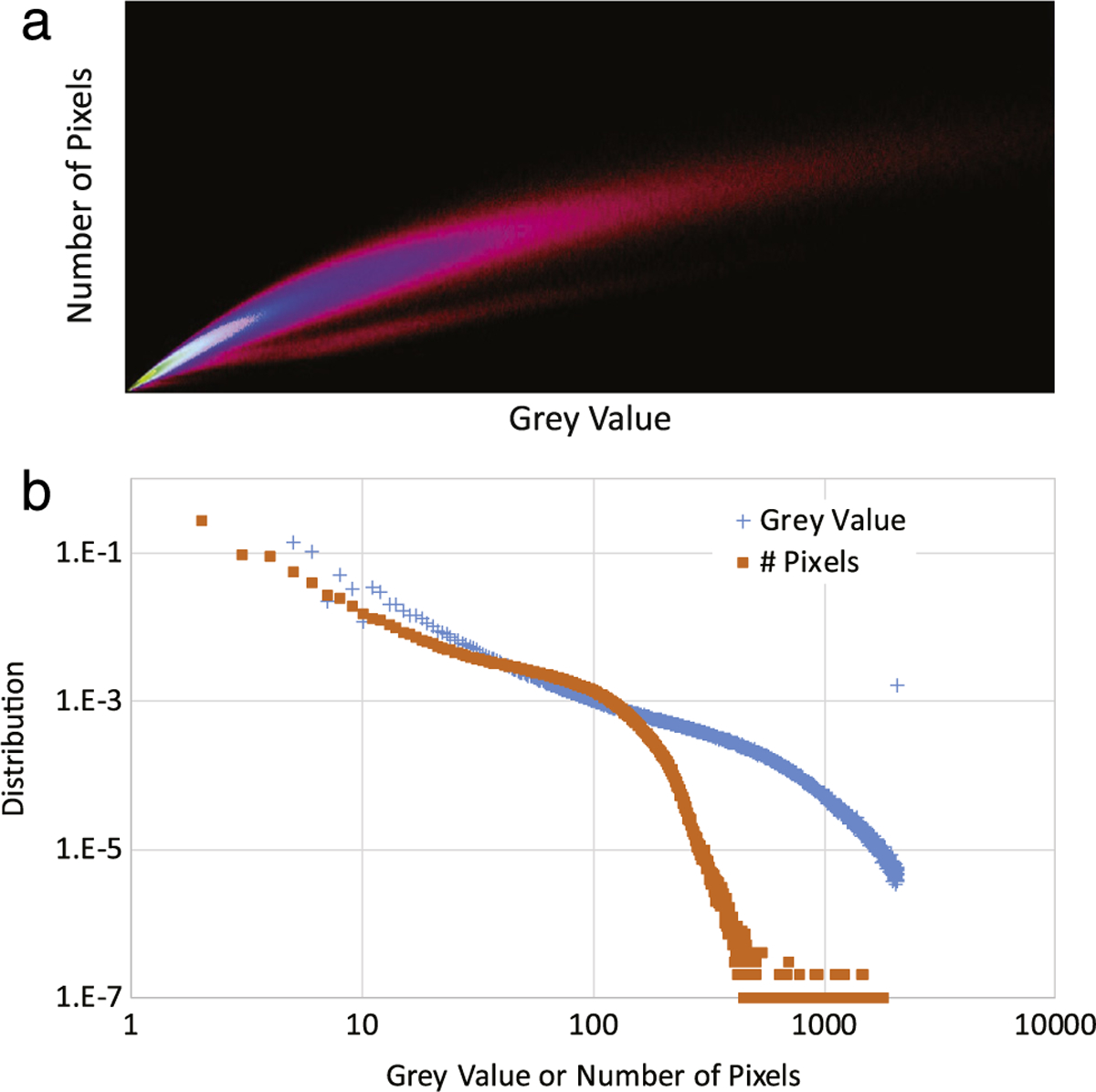
The algorithm tallies the area and number of photons contained within each scintillation event, shown in Fig. 3. Clearly visible are two branches of scintillation events, likely due to the two populations of conversion electrons. To eliminate noise, reduce differential non-linearity and improve spatial resolution, the algorithm applies a threshold in area and number of photons within each event. It was found that a total gray value of 9 and an area of 8 pixels produced high resolution images with sufficient numbers of events. Due to the lower light yield of the lower energy electrons and betas, it may be possible to further improve the reconstructed spatial resolution by discriminating this band.
Fig. 3.

2D histogram of events in terms of number of pixels and total gray values in a scintillation event. The image is the log of the distribution. Clearly visible are two branches of events, likely corresponding to the two populations of electrons stemming from neutron capture in Gd-157 and Gd-155. In (a) the lower, less populated branch corresponds to lower energy electrons stemming from both isotopes.
Due to the difficulty in fabricating a resolution standard for neutron imaging in the 1 μm regime, the spatial resolution has been ascertained from the width of a gold coating applied to a PEMFC test-section. It should be emphasized that such a measure is the upper limit on the resolution (it could be finer) as the test section was not fabricated to be optically flat and the surface profile has not yet been measured. The resolution of 2 μm is determined by fitting an error function to the observed thickness of the gold coating on the edge of the channel. The obtained fit parameters give a coating thickness (including the gold and nickel strike layer) of about 10 μm and a spatial resolution of 2 μm, where the resolution from a Gaussian point spread function described by a standard deviation σ is δ10 = 1.46 * σ.
In the reconstructed images, there was a mild (10% variation) differential nonlinearity (DNL) in the intensity which was only present along the readout lines of the sCMOS, and did not depend on readout mode. The DNL is readily apparent in the Fourier transform of the image, with harmonics corresponding to 1/4 and 1/8. By replacing these harmonics with a median filtered Fourier transform, the DNL is strongly suppressed. The DNL has been corrected in Fig. 4b and c, where the readout axis was in the horizontal plane, but not corrected in Fig. 4a, where the readout axis was in the vertical plane. A future update to the centroiding algorithm would be to include a lookup table correction [10]. Otherwise, there is little noticeable difference in the image resolution comparing the readout modes, so future measurements can make use of the reduced dead time enabled by the rolling shutter and binned region of interest.
4. Conclusions
We have demonstrated the principle of an event based neutron imaging detector that can achieve a spatial resolution of about 2 μm. The use of a GadOx scintillator gives high neutron detection efficiency (80% thermal neutron stopping power), sufficient light yield and good initial spot size. Magnifying the scintillation light ensures that one illuminates more than one pore of the image intensifier so that the center of mass of the scintillation event can be reliably determined. The described algorithm reliably reconstructs a diverse set of images, including data obtained in three separate campaigns over 10 months and three different raw frame acquisition modes.
Presently, the optimized, compiled algorithm takes about 0.5 s to process each frame, the time limitation is in the spatial median filtering steps requiring several days of reconstruction time on a typical desktop computer. As well in the binned raw data acquisition mode, the data set size is about 200 GB for 4 × 10⁵ frames, which produce a final image that is about 2 MB in size. The low noise of the sCMOS is critical to resolving the scintillation events, but the ultimate frame rate of 150 Hz implies a deadtime of 45%, the lowest deadtime achieved in this work was about 25%. As well, there are sources of photon loss in the system, including the quantum efficiency of the image intensifier (50%), the quantum efficiency of the sCMOS (50%) the numerical aperture of the relay lens, and the blur introduced by the output phosphor screen. Improvements on these would be relatively straightforward. Instead of a conventional CMOS or CCD, the intensifier output should be directly coupled to a charge sensitive readout such as a cross-strip or Timepix without a phosphor and relay lens. These readout schemes have already demonstrated 25 ns timing resolution and have implemented hardware based centroiding algorithms, rather than software, so that there would be no deadtime due to frame acquisition or delay in image reconstruction. With such a readout scheme, the described system will be able to image at high spatial resolution with sufficient time resolution to be used on any pulsed thermal neutron imaging instrument. Further improvements to the spatial resolution may also be possible. Utilizing a cold neutron spectrum, it may be possible to further reduce the thickness of the GadOx which would reduce the initial spot size and improve the reconstructed spatial resolution, while maintaining high stopping power. Accounting for the shape of the spot size may improve the accuracy of the center of mass calculation. Discriminating the signal from the lower energy electrons and betas would remove a small background of lower resolution events. Taken together, it is feasible that such a neutron imaging detector system would have a spatial resolution of 1 μm with a field of view of at least 1 × 1 cm.
Acknowledgments
The authors gratefully acknowledge useful discussions with J. Vallerga, A. Martin, and O.H.W. Siegmund of Sensor Sciences. The fuel cell hardware was provided R.L. Borup, R. Mukundan, D. Spernjak of the Los Alamos National Laboratory fuel cell program. This work was supported by the U.S. Department of Commerce, the NIST Radiation and Physics Division, the Director’s office of NIST, the NIST Center for Neutron Research, and the Department of Energy interagency agreement No. DE_AI01–01EE50660.
References
- [1].S Hussey D, Jacobson DL, Applications of neutron imaging and future possibilities, Neutron News 26 (2015) 19–22. [DOI] [PMC free article] [PubMed] [Google Scholar]
- [2].Ziegler JF, Biersack J, Littmark U, The Stopping and Range of Ions in Matter, Pergamon Press, 1985. [Google Scholar]
- [3].Arif M, Jacobson DL, Hussey DS, VA5 neutron imaging study of the water transport in operating fuel cells, in: DOE Hydrogen Program FY 2010 Annual Progress Report, 2010, pp. 686–692. [Google Scholar]
- [4].Siegmund O, Tremsin A, Vallerga J, McPhate J, Microchannel plate cross-strip detectors with high spatial and temporal resolution, Nucl. Instrum. Methods A 610 (1) (2009) 118–122. [DOI] [PMC free article] [PubMed] [Google Scholar]
- [5].Vallerga J, Raffanti 1R, Tremsin A, McPhate J, Siegmund O, MCP detector read out with a bare quad Timepix at kilohertz frame rates, in: 12th International Workshop on Radiation Imaging Detectors, http://dx.doi.org/101088/1748-0221/6/01/C01049. [Google Scholar]
- [6].Siegmund OHW, Vallerga JV, Martin A, Feller B, Arif M, Hussey DS, Jacobson DL, A high spatial resolution event counting neutron detector using microchannel plates and cross delay line readout, Nucl. Instrum. Methods Phys. Res. A 579 (2007) 188–191. [Google Scholar]
- [7].Trtik P, Hovind J, Grünzweig C, Bollhalder A, Thominet V, David C, Kaestner A, Lehmann EH, Improving the spatial resolution of neutron imaging at Paul Scherrer Institut – The Neutron Microscope Project, Phys. Procedia 69 (2015) 169–176. [Google Scholar]
- [8].Vavrik D, Holik M, Jakubek J, Jakubek M, Kraus V, Krejci F, Soukup P, Turecek D, Vacik J, Zemlicka J, Modular pixelated detector system with the spectroscopic capability and fast parallel read-out, in: 15th International Workshop on Radiation Imaging Detectors 23–27, June, 2013, Paris, France, http://dx.doi.org/101088/1748-0221/9/06/C06006. [Google Scholar]
- [9].Song Y, Conner J, Zhang X, Hayward JP, Monte Carlo simulation of a very high resolution thermal neutron detector composed of glass scintillator microfibers, Appl. Radiat. Isot. 108 (2016) 100–107. [DOI] [PubMed] [Google Scholar]
- [10].Vallerga JV, Siegmund OHW, Dalcomo J, Jelinsky PN, Proc. SPIE 3019, Solid State Sensor Arrays: Development and Applications, 156, April 25, 1997, http://dx.doi.org/101117/12275171. [Google Scholar]
- [11].Carter MK, Patchett BE, Read PD, Howarth JR, Transputer based image photon counting detector, Proc. SPIE 1655 (1992) 138–142. [Google Scholar]
- [12].Dietze M, Felber J, Raum K, Rausch C, NIMA 377 (1996) 320. [Google Scholar]
- [13].Hussey DS, Jacobson DL, Arif M, Coakley KJ, Vecchia DF, In situ fuel cell water metrology at the NIST neutron imaging facility, J. Fuel Cell Sci. Technol 7 (2) (2010) 021024. [Google Scholar]
- [14].Williams SH, Hilger A, Kardjilov N, Manke I, Strobl M, Douissard PA, Martin T, Riesemeier H, Banhart J, Detection system for microimaging with neutrons, J. Instrum (2012). 10.1088/1748-0221/7/02/P02014. [DOI] [Google Scholar]
- [15]. Certain trade names and company products are mentioned in the text or identified in an illustration in order to adequately specify the experimental procedure and equipment used. In no case does such identification imply recommendation or endorsement by the National Institute of Standards and Technology, nor does it imply that the products are necessarily the best available for the purpose.
- [16].Kandlakunta P, Cao LR, Mulligan P, Measurement of internal conversion electrons from Gd neutron capture, Nucl. Instrum. Methods Phys. Res. Sect. A 705 (2013) 36–41. [Google Scholar]
- [17].Hussey DS, Spernjak D, Weber AZ, Mukundan R, Fairweather J, Brosha EL, Davey J, Spendelow JS, Jacobson DL, Borup RL, Accurate measurement of the through-plane water content of proton-exchange membranes using neutron radiography, J. Appl. Phys. 112 (2012) 104906. [DOI] [PMC free article] [PubMed] [Google Scholar]


