Abstract
The predominant geometry for a neutron imaging experiment is that of a pinhole camera. This is primarily due to the difficulty in focusing neutrons due to the weak refractive index, which is also strongly chromatic. Proof of concept experiments demonstrated that neutron image forming lenses based on reflective Wolter mirrors can produce quantitative, high spatial resolution neutron images while also increasing the time resolution compared to the conventional pinhole camera geometry. Motivated by these results, we report the design of a neutron microscope where two Wolter mirrors replace condensing and objective lenses, in direct analogy with typical visible light microscopes. Ray tracing results indicate that this system will yield 3 μm spatial resolution images with an acquisition time of order <1 s (104 faster than currently possible at this spatial resolution) with a field of view of about 5 mm in diameter.
1. Introduction
Neutron imaging yields unique insight into materials as the probe primarily interacts with the nuclei through the strong nuclear force such that the sensitivity to a given isotope or element appears to vary somewhat randomly across the periodic table of elements. In particular, neutrons readily penetrate several centimeters of many metals, so that it is straightforward to image an object in a sample environment including cryostats, high magnetic fields, furnaces, high pressure rigs. As well, one can perform in operando studies of the actual system of interest, such as, for example proton exchange membrane fuel cells. However, in the case of conventional neutron imaging, one must pay very close attention to the size of these sample environments along the beam path. This is because conventional neutron imaging instruments are pinhole cameras, and the fundamental limit to the spatial resolution is given by the geometric unsharpness: for L ≫ D, where z is the sample to detector distance, D is the aperture size, and L is the aperture to detector distance. At the same time, the fluence rate of the beam (and hence the exposure time) scales as , so that a linear improvement in spatial resolution requires a quadratic increase in exposure time (for a circular aperture). Due to the relatively weak neutron source strength, compared to synchrotron X-ray sources, apertures on the order of a centimeter are required to have a neutron fluence rate that permits acquiring an image with good counting statistics in a reasonable time (seconds to minutes). For example, high resolution fuel cell imaging at the NIST neutron imaging facility uses a 1 mm × 10 mm slit aperture with a neutron fluence rate of about 7×105 cm−2 s−1, requiring about 20 min for an image [1]. When employing a sample environment there is a reciprocal relationship between the required spatial and the desired temporal resolution. Given the relatively weak strength of current and proposed neutron sources, the choice is between up to a few days for a high spatial resolution tomography, or significant degradation in spatial resolution for temporal resolution in the minutes. Despite this unfortunate situation, there have been many valuable measurements made with neutron imaging of systems with somewhat large sample environments including fuel cells [2–7], cryogenic liquid/vapor properties [8], soil water content evaporation [9,10], neutron depolarization of quantum magnets [11].
The use of the pinhole camera geometry is driven by the difficulty in focusing neutron beams. Neutrons interact with matter through the strong nuclear force and the electromotive force due to the intrinsic spin of the neutron. The refractive power of both interactions is weak, scaling as ~(1–10−4 λ2) ([λ, nm]) resulting in typical focal lengths for a single lens on order 100 m [12]. However, similar to low energy X-rays, neutrons experience total external reflection for grazing angles of incidence. In the case of Ni, the critical angle scales as θc ~ 1° * λ [nm]. For a cold neutron source with characteristic wavelength of about 0.4 nm, focusing mirrors can be made with focal lengths of order a few meters. As well, the angle of reflection is achromatic so that a polychromatic neutron beam can be sharply focused. However, the critical angles are wavelength dependent and so the mirrors are more efficient when used with cold neutron spectra (λ > 0.4 nm).
Wolter mirrors are composed of two confocal conic sections (hyperboloids, paraboloids, and ellipsoids); the use of two reflections eliminates coma and is a better approximation of the Abbe sine condition in geometrical optics [13]. These optics were first proposed as X-ray microscopes, but found their primary use in the field of X-ray astronomy [14]. As an example, the CHANDRA observatory is a Wolter mirrors telescope, where the first conic section is a parabola with its focus at infinity and the second conic section is a hyperbola. CHANDRA is composed of 4 nested mirrors, which are composed of about 2 cm thick glass substrates polished to a figure error of about 2.4 μrad (0.5 arcsec) with a coating of iridium [15]. There has been an ongoing effort in many X-ray optics groups, including at Marshall Space Flight Center (MSFC), to realize nested mirrors with low figure error based on replicated nickel metal shells [16]. The development of high-resolution Ni films is also suitable for use with neutron beams as nickel has the largest critical angle of any element. Briefly, the process involves electroplating a nickel film (<~1 mm thick) on an accurately polished aluminum substrate. In an ice bath, the film is separated from the substrate due to the large difference in the coefficients of thermal expansion of the two materials. The best effort of the MSFC group to date is the FOXSI telescope where a figure error of about 35 μrad (7 arcsec) was realized [17]. It is expected that a best figure error of 1 μrad is ultimately achievable.
In the remainder of this report, the review section describes the prototype Wolter mirrors used for three proof of concept imaging measurements. We then describe the anticipated beam line at the National Institute of Standards and Technology (NIST) Center for Neutron Research (NCNR) at which the designed Wolter mirrors system will be installed and the expected performance.
2. Review
2.1. Prototype optic description
The prototype Wolter mirrors are described in detail in [18]. To briefly summarize, the device is composed of three nested shells of natural nickel with hyperbolic and ellipsoidal sections, see Fig. 1. Each section is about 3 cm long, and the intersection radius is about 1.5 cm. The wall thickness of the shells is about 1 mm. The hyperbolic focal length is about 0.64 m while the ellipsoidal focal length is about 2.56 m, producing an image magnification of 4 (or minification of 0.25 if the optic is reversed). The figure error of the test device was about 30 arcsec. The spatial resolution of the resulting image on the optical axis is the product of the figure error and focal length so that the spatial resolution is about 100 μm.
Fig. 1.
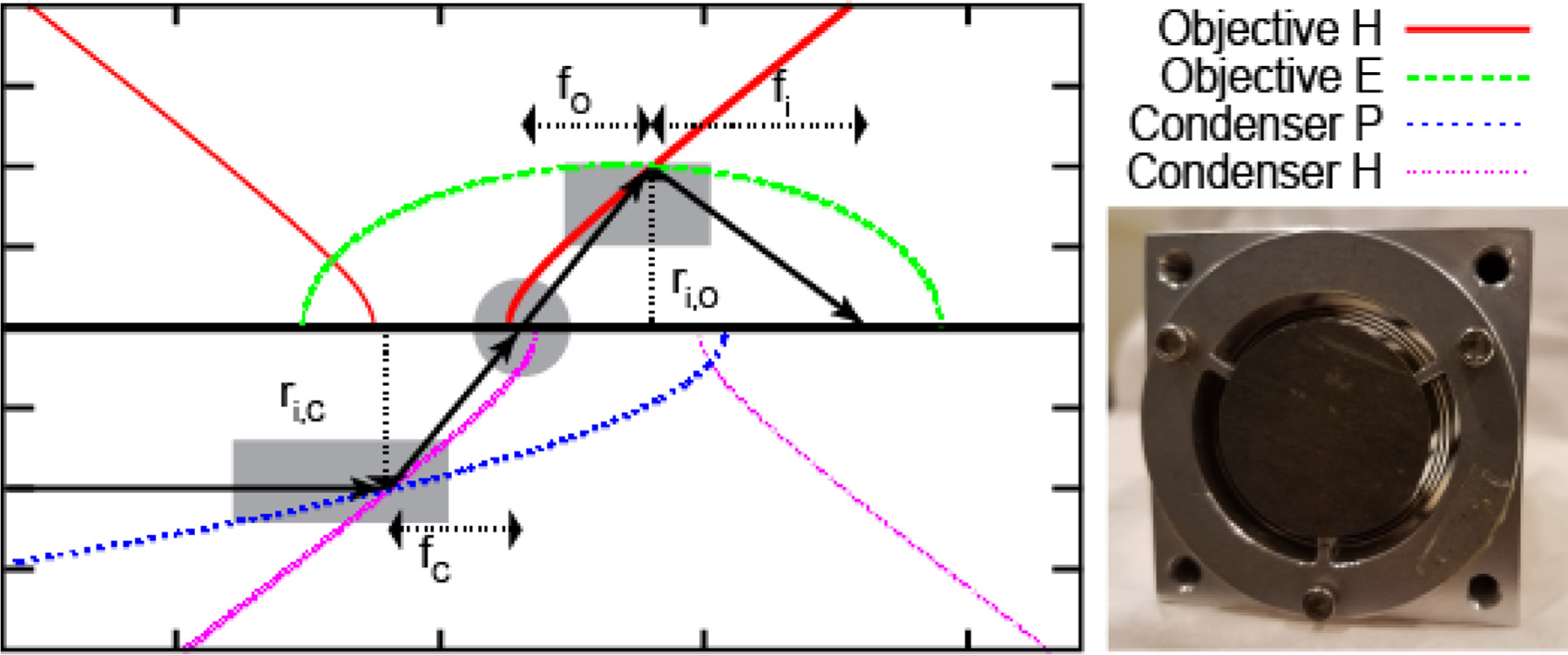
The generic geometry for a Wolter optic microscope consisting of a condenser (lower half) and objective (upper half). The neutron beam passes from left to right, and one ray is shown as a solid black arrow as it traverses the optical system, first doubly reflecting from the intersection point on the condenser, passing through the sample (gray circle) and then doubly reflecting from the intersection point on the objective. The parameters to be optimized, shown as dashed arrows, include the intersection radii of the condenser (ri,C) and objective (ri,O), the focal length of the condenser (fc), the objective’s object (fO) and the image (fi) focal distances. The detector sits at fi. The gray rectangles indicate the portions of the conic sections that comprise the mirrors. While the diagram shows the condenser and objective foci meeting at the same position along the optical axis, one of the design considerations is to include a separation of these foci. The two ‘‘imaginary’’ branches of the hyperbolic sections are shown as thinner lines to demonstrate the confocal constructions. A photo of the prototype objective used in the proof of concept experiments is shown with the upstream face showing. The leading edges of two nested coaxial mirrors are visible in the opening between the cadmium beamstop and the aluminum frame.
2.2. Focusing at MIT
The first proof of concept measurement was conducted at the neutron source at the Massachusetts Institute of Technology (MIT) [19]. A 1 cm aperture was placed at the elliptical focus and the image at the hyperbolic focus showed the expected minification of 4. The focal spot size was analyzed to confirm the expected figure error.
2.3. Imaging at NIST
The second proof of concept measurement was conducted on the neutron depth profile beam line which was on NG1 of the NCNR [20]. Due to the temporary nature of the measurement, the flight path was not evacuated, so that there was significant loss of intensity due to neutron scattering in air. A 1 cm aperture illuminated the sample position. The prototype optic was placed 0.64 m downstream of the sample position and the detector was placed at the elliptical focal point so that the neutron image magnification was 4. The detector was a microchannel plate detector with field of view 4 cm and spatial resolution 15 μm [21] but was operated with a pixel pitch of 50 μm to reduce exposure times. In order to compare with conventional imaging, a set of images with the sample placed directly in front of the detector and the prototype optic removed from the optical path were also recorded, see Fig. 2. The first sample was a pinhole mask in a foil of Gd. The pinholes had diameter 100 μm and center to center separation of 200 μm. The second sample was a portion of a proton exchange membrane fuel cell, which showed that a quantitative measure of the water content in reasonable agreement with conventional imaging could be obtained [22]. These measurements demonstrated the feasibility of producing magnified neutron images. The magnification provided by the optic, that is an expansion at the image focal plane of the neutron intensity at the object focal plane, yields an improved spatial resolution of the detector. As well, the observed spatial resolution was in keeping with expectations based on the figure error stated in Section 2.1.
Fig. 2.
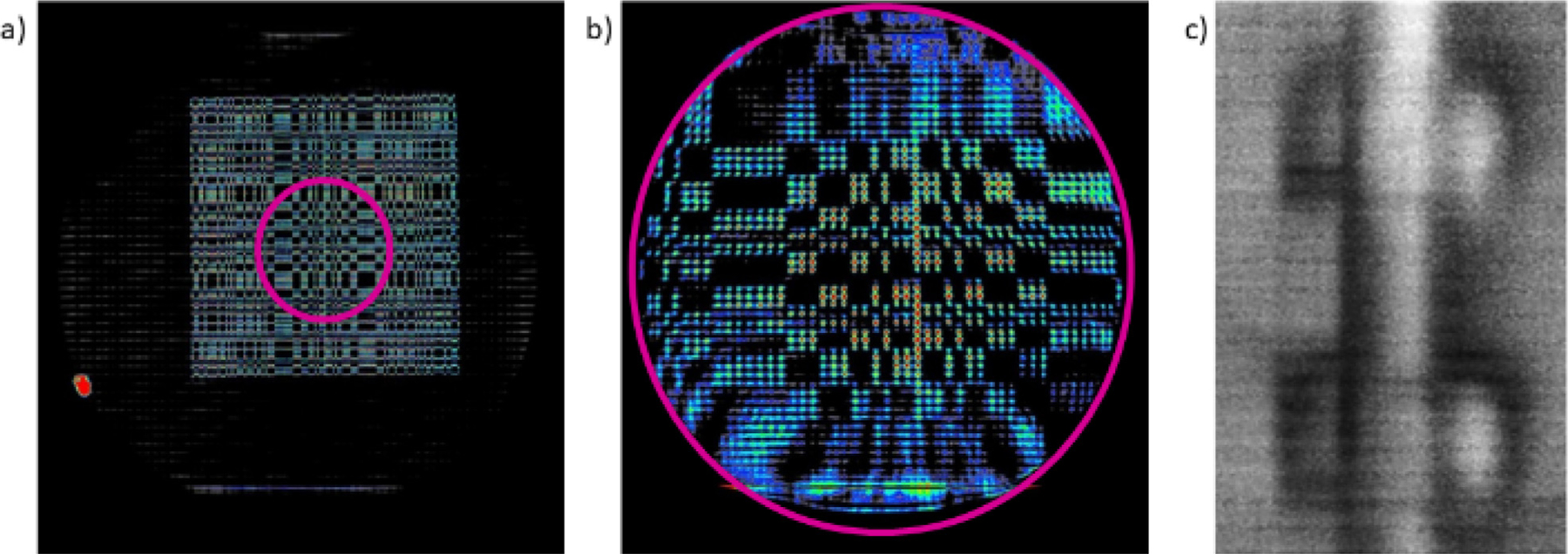
Images from the proof of concept measurement at NIST. (a) Contact image of a pinhole array. (b) Magnified Wolter mirrors image of the same pinhole mask, where the magenta circles indicate the same region of interest. (c) A Wolter mirrors image of a fuel cell test section.
2.4. With condenser at FRM II
The final proof of concept measurement was conducted at the ANTARES beam line of the FRM-II reactor in Garching, Germany [23]. The primary goal of this study was to provide spatially resolved images of a quantum magnet undergoing a ferromagnetic phase transition at cryogenic temperatures and high pressure (>10 kbar). The need to spin polarize the neutron beam placed the sample position several meters from the aperture so that the beam was strongly collimated and would not effectively illuminate the phase space acceptance of the Wolter mirrors. To counteract this, a parabolic neutron supermirror was placed upstream of the sample to serve as a condenser, which is a simplified version of the general scheme shown in Fig. 1. Images of the neutron intensity at the sample position were acquired as the position of the condensing optic was changed with respect to the object focal distance of the prototype Wolter optic. Comparing these measurements with ray tracing of the output of the condenser indicated that the Wolter optic was indeed magnifying the neutron intensity at the object focal plane. Further, when compared to conventional neutron imaging, a factor 5 improvement in spatial resolution and a factor of 2 improvement in time resolution were realized while reproducing similar quantitative neutron polarization results.
These proof of concept measurements demonstrated that a neutron microscope based on Wolter mirrors produces quantitative images and has the potential to improve the spatial and temporal resolution, especially when sample environment or beam conditioning optics places a significant distance between the sample and the imaging detector.
3. Design of the neutron microscope for the NIST cold neutron imaging instrument
3.1. NIST cold neutron imaging instrument
The Wolter optic system was designed for the planned upgraded cold neutron imaging instrument (CNII.ii) at NIST. The CNII.ii will be located at the end of NG6. During the scheduled change of the NCNR cold source in calendar years 2023 to 2024, the straight, Ni-58 coated neutron guides for NG6 will be replaced with curved M = 2 neutron supermirror guides. Using phase space tailoring [24,25], with a radius of curvature about 1400 m, the endstation will no longer have a direct line of sight to the reactor core eliminating the fast neutron and gamma ray backgrounds, while maintaining good transport and uniform phase space for neutrons with λ > 0.3 nm. Ray tracing of this curved guide predicts a thermal equivalent neutron fluence rate (or capture flux) of about 6.8 × 109 cm−2 s−1. Higher M-value guides were investigated but yield only a ~10% increase in the thermal equivalent fluence rate due to the linear decay in the reflectivity of the mirrors for incident angles above ~2θc and the ~55 m length of guide, and thus do not warrant the higher cost. The neutron guide will be shared with a monochromatic instrument, so that the top 10 cm of the 15 cm tall, 6 cm wide guide, will be dedicated to the imaging instrument located on the end station. A section of M = 2 guide with length 3 m, and cross-section 10 cm × 6 cm will span the distance from the end of the entire guide into the experimental area of the CNII.ii.
The total length of the neutron guide feeding the CNII.ii will be reduced by about 5 m so that the flight path available inside the experimental area will be about 15 m. To summarize, CNII.ii is anticipated to have a neutron spectrum with longer characteristic wavelength, a 3.4 gain in thermal equivalent fluence rate, a larger beam, and a longer flight path that enables incorporating many neutron optical components. These changes strongly influenced the design and capability of the neutron microscope described below.
3.2. The NIST neutron microscope
3.2.1. Constraints
The most important design parameter is the expected figure error and overall angular resolution of objective optic. Based on current best efforts, it is expected that the angular resolution of a single mirror will be about 5 μrad while the angular resolution of the system will be about 10 μrad. The second constraint is the minimum intersection radius of 20 mm that can be produced at this best figure error. We assume that the final mirror coating will be 58Ni and not a Ni/Ti multilayer supermirror. This is because a differential deposition step maybe required to reach the target figure error [26]. In this method, the profile of a mirror is measured, and additional material is selectively deposited post separation where troughs are identified. The supermirror coating is applied on the mandrel before the separation, and thus is incompatible with the differential deposition [27]. Efforts are ongoing to improve multilayer coating, but the figure error is about 150 μrad, which is too coarse for imaging applications [27] but maybe sufficient for creating intense focal spots.
The maximum mirror length that can be produced by Marshall Space Flight Center (MSFC) is 60 cm. Based on ray tracing results and confirmed with measurements it was found the field curvature of the objective optic scales proportionally to the optic length and inversely proportional to the square root of the radius, so that shorter objective mirrors yield higher spatial resolution [28]. Given these constraints and assumptions, we performed ray tracing to determine the system parameters that yielded the highest fraction of the incident flux focused onto the detector. The basic geometry of the optical system s shown in Fig. 1. The condenser is Wolter type I telescope, and the confocal parabolic and hyperbolic sections are drawn on the bottom half of the plot. The objective is Wolter type I microscope, and the confocal hyperbolic and elliptical sections are drawn on the top half of the plot. The design parameters of both the condensing optic and objective optic were simultaneously varied so that the performance of the entire system was maximized.
3.2.2. Description of the optical system
The optical system to be optimized consists of the neutron source, which is the NG6 guide, the condensing optic, and the objective optic. The parameters of the NG6 guide are taken as a given, specifically a cross-sectional area 10 cm × 7 cm, beam divergence of that due to an M = 2 supermirror, and a cold neutron spectrum as shown in Fig. 3. The condensing optic is a telescope, with a parabolic and hyperbolic section, as the M = 2 divergence is still low enough to approximate a collimated beam. The displacement from the guide, intersection radii, focal length, and number of shells of the condenser were varied. The length of the optic is 60 cm, with equal length of the parabolic and hyperbolic sections. The figure error of the condenser optic is unimportant, as one wishes to create the largest, uniform, field of view at the sample position, and the routinely achieved figure error of 20 arcsec was used in the ray tracing. The objective optic is a Wolter type-I microscope lens with each shell composed of an elliptical and hyperbolic section. The parameters of the objective lens that were allowed to vary include magnification, focal length, intersection radii, number of shells, the length of the shells, and the displacement from the focal point of the condensing optic [29].
Fig. 3.
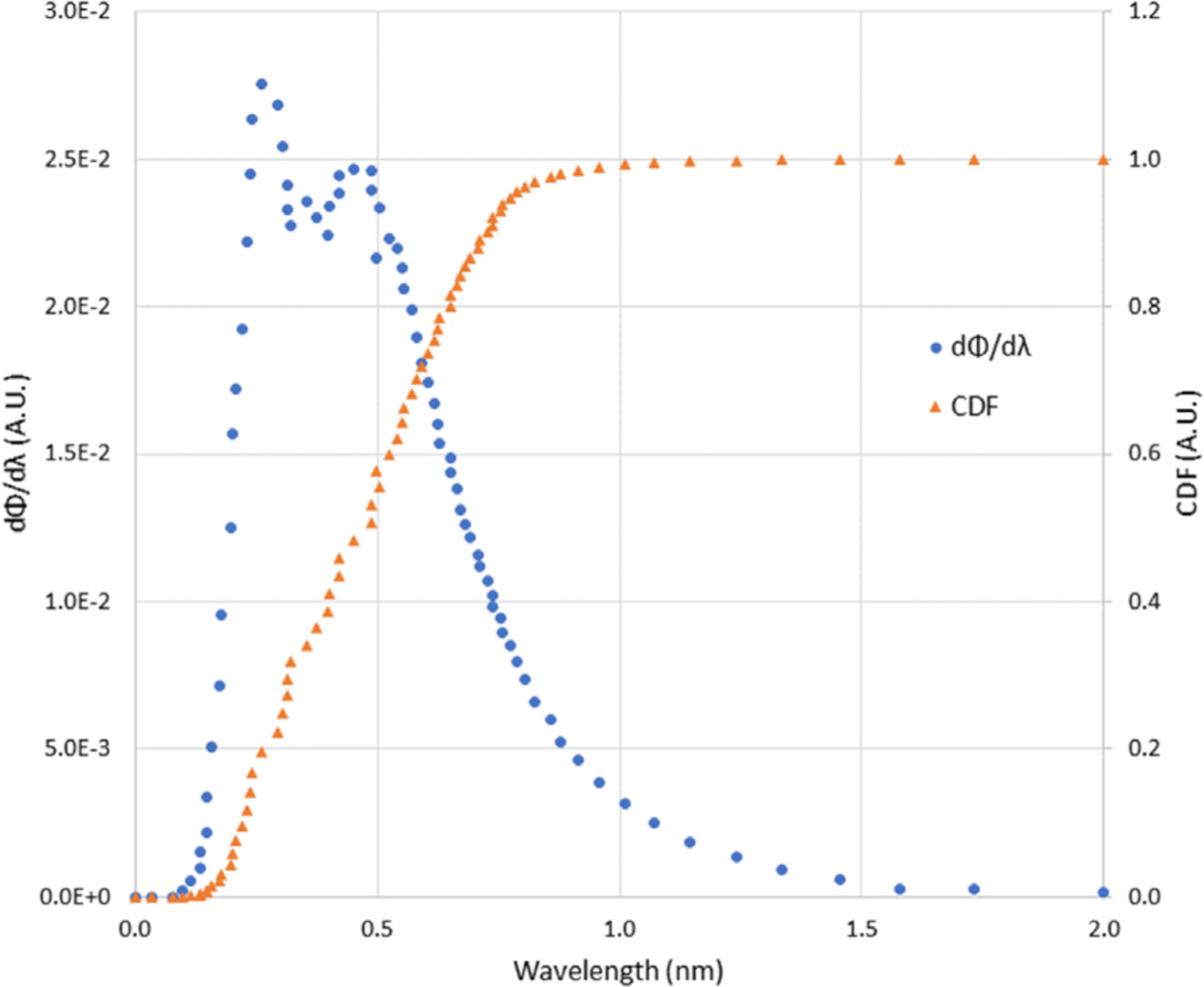
Anticipated spectrum for the CNII.ii with curved M = 2 supermirror guides viewing the liquid D2 moderator. The cumulative distribution function (CDF) is given on the right hand axes.
3.2.3. Ray tracing results
While the final parameters for the condenser and objective optics were determined in concert, the range of focal lengths and intersection radii for the condenser that realized the most intense focal spot were determined separately first. To reduce simulation time in these initial studies, 20 different intersection radii were used for each condenser focal length. The simulation tracked from which mirror shell a neutron reflected and whether the final trajectory was within a square aperture of 25 mm × 25 mm placed at the focal plane. As shown in Fig. 4, there is a broad maximum in the focal length centered at about 1250 mm for the most intense beam focused onto the aperture. Shown in Fig. 5 are the fraction of neutrons that are doubly-focused from each mirror pair, where the intersection radius of each mirror increases with increasing shell number. The majority of the focused neutrons fall within 6 shells, and the constraint of a minimum intersection radius of 20 mm does not strongly limit the performance of any of the considered focal lengths. Since the spectrum has a maximum near 0.5 nm, the critical reflection angle is about 0.5° for Ni-58, so that the optimal angle at the intersection radius is about 1°. For longer focal lengths, this optimal reflection angle is not realized until larger intersection radii. With about 10.5% of the guide focused onto a 25 mm square aperture represents an average fluence rate of about 7 × 109 cm−2 s−1 over the sample, though the focal spot size varies as discussed below.
Fig. 4.
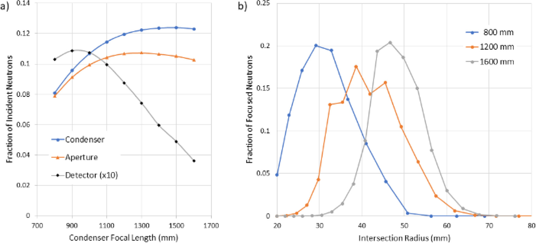
(a) Fraction of neutrons from the guide that are doubly reflected by the condenser and are focused onto the 25 mm square aperture. An objective with 20 shells, focal length of 750 mm and magnification of 10 was included to estimate the fraction of neutrons successfully transported to the detector, in order to display on the same axis, this fraction was multiplied by 10. The condenser focal length resulting in the maximum throughput to the aperture differs significantly from that to the detector, highlighting the importance of simultaneously optimizing both lenses. (b) Fraction of doubly-reflected neutrons from a given mirror shell for three of the condenser focal lengths in (a). The results are derived from one ray tracing instance, and the estimated standard deviation for (a) is about 0.001 and for (b) is about 0.003.
Fig. 5.
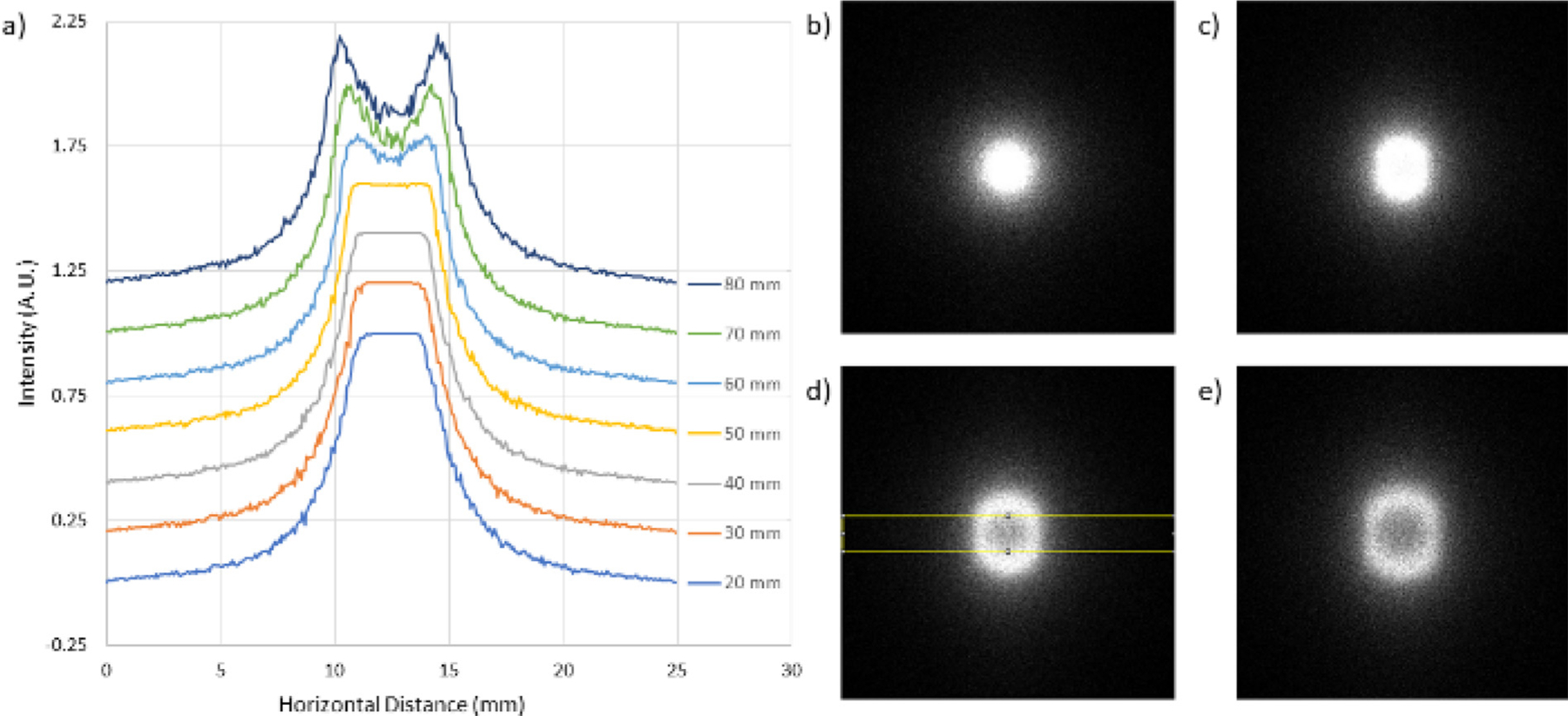
Field of view downstream of the condenser focus. (a) Horizontal line profiles of the intensity normalized to the maximum value over the region of interest shown in the yellow box in (d). The profiles have been shifted vertically for clarity. With a displacement of about 50 mm, the field of view is about 5 mm. The images (b)–(e) are the flat field for a displacement of 20 mm, 50 mm, 70 mm, and 80 mm respectively. The elongation in the vertical direction is due to the rectangular shape of the CNII.ii guide, which is 7 cm wide and 10 cm tall.
The focused neutron beam emanating from the condenser is an annulus as it approaches and departs from the focal plane. As demonstrated by the proof of concept measurements discussed in Section 2.4, one can place the objective optic such that object focal plane is displaced from that of the condenser so as to increase the field of view. Fig. 5 shows how the intensity evolves downstream of the condenser focal point with 5 mirror shells and focal length of 1000 mm. The largest uniform field of view is about 5 mm × 5 mm at a position of 50 mm downstream of the focal point. This central region accounts for about 68% of the intensity in the 25 mm × 25 mm square aperture. For each condenser focal length, a similar study was conducted and for the final optimization, the object focal distance of the objective was placed so as to yield the largest field of view.
The next study varied the magnification and focal length of the objective while the focal length of the condenser was also varied to determine optical parameters that maximized the fraction of incident neutrons focused onto the detector. In general, it was found that a similar focused fraction of neutrons could be achieved for any given pairing. As one would expect, longer focal lengths for both lenses favored larger intersection radii. Given the assumed best angular resolution, the goal spatial resolution of about 3 μm, and to ensure the optical system would fit inside CNII.ii, a magnification of 10 and object focal distance of 750 mm was chosen to complete the optimization of the objective and condenser lenses.
Next, we show which mirror shells contribute most to neutron throughput as a function of condenser focal length and the length of the objective shells. From these simulations, the optimal condenser focal length was found to be about 1000 mm. We sought to maximize the throughput of the system with regards to the number of shells comprising the objective and condenser. Fig. 6 provides a general summary of the results for a condenser with 5 shells and an objective with 6 shells. In Fig. 6a, the contribution of each objective mirror shell to the overall neutron transport is shown. Even for the shortest shell considered, the largest shell radius does not significantly contribute to the intensity at the detector. More importantly, as the shell length is reduced, the overall neutron transport through the system is reduced. As a result, the final design was optimized using a condensing optic with 6 shells and an objective optic with 5 shells. Repeating the objective shell length study under these conditions yielded a linearly increasing throughput with shell length, so that the final half shell length for the objective was 100 mm. A length of 100 mm was chosen as the maximum length to limit field curvature.
Fig. 6.
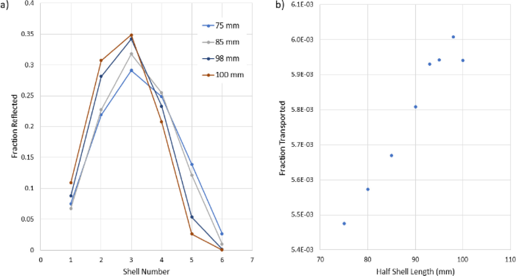
Results of the objective shell length study. (a) The relative contribution of each objective shell to the overall system throughput. (b) The overall system throughput as a function of shell length.
Finally, the minimum radius of the objective, the minimum radius of the condenser, and the focal length of the condenser were determined. Shown in Fig. 7 are the results for the condenser parameters, where multiple simulations were used. The design of the optical system is now complete. The condensing optic is composed of 6 shells in a paraboloid-hyperboloid configuration with each section length being 300 mm and a focal length of 1000 mm. The intersection radii are 26.5 mm, 29.417 mm, 32.545 mm, 35.899 mm, 39.496 mm, and 43.353 mm. The sample position is about 50 mm downstream of the condenser focal point. The objective optic is composed of 5 shells in a hyperboloid-ellipsoid configuration, with each section being 100 mm in length. The intersection radii are 20.242 mm, 23.535 mm, 27.183 mm, 31.224 mm, and 35.702 mm. The object focal length is 750 mm and the image focal length is 7500 mm. While not discussed in detail above, a separation distance between the end of the guide and the condenser of 2500 mm was included. The complete optical system is sketched in Fig. 8.
Fig. 7.
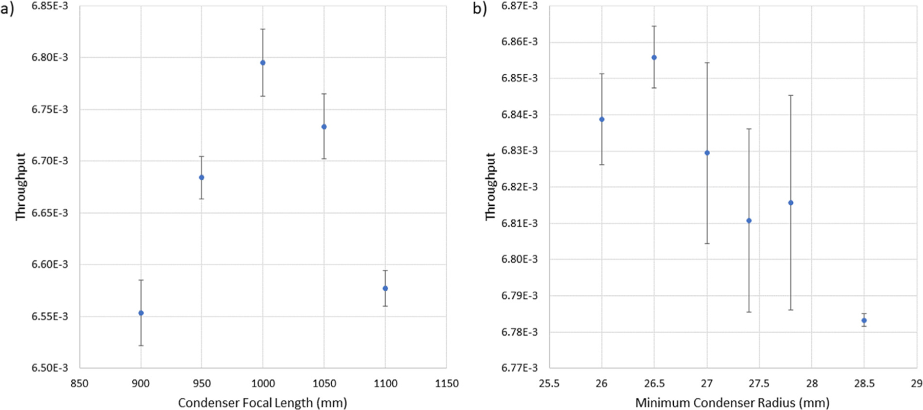
Total neutron throughput as a function of (a) condenser focal length (b) minimum condenser intersection radius for focal length 1000 mm. Uncertainties are the root mean square deviation of simulations using the same lens parameters. The minimum intersection radius for the objective had been previously determined.
Fig. 8.
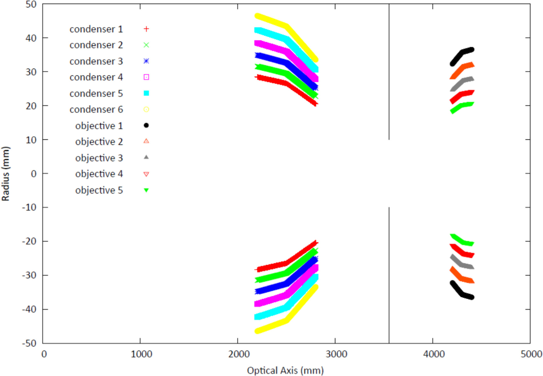
Sketch of the Wolter mirrors neutron microscope system. The end of the straight section of guide that is 10 cm tall by 7 cm wide is positioned at 0 mm along the optical axis. The condenser, a paraboloid/hyperboloid Wolter type I consisting of 6 pairs of nested shells, with focal length 1000 mm, is placed 2500 mm downstream of the end of the guide. The sample aperture is placed 1050 mm downstream of the condenser to allow a larger field of view. The objective lens is 750 mm downstream of the sample aperture and is a Wolter type I consisting of 5 nested pairs of hyperboloid/ellipsoid mirror shells. The detector, not shown, is positioned along the optical axis at a distance of 11 800 mm from the end of the guide.
4. Discussion and conclusions
Simulations of the final optical system show that the condenser focuses about 6.35% of the guide fluence rate into the 25 mm square aperture, while the objective optic transports 0.68% to the detector. Taking the anticipated thermal equivalent fluence rate at the end of the guide of 6.83 × 109 cm−2 s−1 and assuming that the sample sits in the 5 mm × 5 mm area of uniform intensity, the corresponding fluence rate on the sample is about 8.9 × 109 cm−2 s−1, while yielding an image spatial resolution of about 3 μm. A conventional imaging setup at the CNII.ii for a 10 mm separation of the sample to the detector, and a pinhole-to-detector length of 11 800 mm would require a pinhole diameter of about 3.5 mm for a geometric unsharpness of 3 μm. For a beam divergence of +/−1°, the fluence rate at the detector will be about 5.05 ×105 cm−2 s−1, more than 4 orders of magnitude reduced from the designed microscope. The Wolter mirrors neutron microscope will thus modestly improve the spatial resolution and drastically improve the temporal resolution that will be achievable for neutron imaging. As well, bulky sample environments and neutron optical components can be used without the need to compromise spatial resolution for temporal resolution. While the optical system is anticipated to be complete at the end of calendar year 2021, the upgrade CNII.ii is expected to be operational in the summer of 2024. Thus, the initial performance of the optical system at the present cold neutron imaging instrument will be limited due to space constraints.
Acknowledgments
This work was supported by the U.S. Department of Commerce, the NIST Radiation Physics Division, United States of America, the Director’s office of NIST, United States of America, and the NIST Center for Neutron Research, United States of America. The research at MIT was supported by the U.S. Department of Energy, Office of Basic Sciences, under Award #DE-SC0017098 (ray-tracing simulations) and the U.S. Department of Commerce, National Institute of Standards and Technology award 60NAN-B15D361 (experimental tests). The authors wish to acknowledge the pioneering efforts of Mikhail Gubarev who sought to transform X-ray telescopes to neutron microscopes but passed away before the system could be fully realized.
Footnotes
CRediT authorship contribution statement
D.S. Hussey: Conceptualization, Software, Writing - original draft, Funding acquisition. M. Abir: Validation. J.C. Cook: Investigation. D.L. Jacobson: Resources. J.M. LaManna: Resources. K. Kilaru: Resources. B.D. Ramsey: Resources. B. Khaykovich: Conceptualization, Software, Writing - review & editing, Funding acquisition
Declaration of competing interest
The authors declare that they have no known competing financial interests or personal relationships that could have appeared to influence the work reported in this paper.
References
- [1].Hussey DS, et al. , Accurate measurement of the through-plane water content of proton-exchange membranes using neutron radiography, J. Appl. Phys 112 (10) (2012) 10.1063/1.4767118. [DOI] [PMC free article] [PubMed] [Google Scholar]
- [2].Trabold TA, Owejan JP, Gagliardo JJ, Jacobson DL, Hussey DS, Arif M, Use of neutron imaging for proton exchange membrane fuel cell (PEMFC) performance analysis and design, Handb. Fuel Cells (2010). [Google Scholar]
- [3].Hickner MA, Siegel NP, Chen KS, Hussey DS, Jacobson DL, Arif M, Understanding liquid water distribution and removal phenomena in an operating PEMFC via neutron radiography, J. Electrochem. Soc 155 (3) (2008) 10.1149/1.2825298. [DOI] [Google Scholar]
- [4].Kim S, Mench MM, Investigation of temperature-driven water transport in polymer electrolyte fuel cell: Phase-change-induced flow, J. Electrochem. Soc 156 (3) (2009) B353, 10.1149/1.3046136. [DOI] [Google Scholar]
- [5].Steinbach AJ, et al. , Anode-design strategies for improved performance of polymer-electrolyte fuel cells with ultra-thin electrodes, Joule (2018) 10.1016/j.joule.2018.03.022. [DOI] [Google Scholar]
- [6].Lehmann EH, Boillat P, Scherrer G, Frei G, Fuel cell studies with neutrons at the PSI’s neutron imaging facilities, Nucl. Instrum. Methods Phys. Res. A 605 (1–2) (2009) 123–126, 10.1016/j.nima.2009.01.143. [DOI] [Google Scholar]
- [7].Hartnig C, Manke I, Kuhn R, Kleinau S, Goebbels J, Banhart J, High-resolution in-plane investigation of the water evolution and transport in PEM fuel cells, J. Power Sour 188 (2) (2009) 468–474, 10.1016/j.jpowsour.2008.12.023. [DOI] [Google Scholar]
- [8].Bellur K, et al. , A new experiment for determining evaporation and condensation coefficients of cryogenic propellants, 2016. [DOI] [PMC free article] [PubMed] [Google Scholar]
- [9].Zheng W, et al. , Plant growth-promoting rhizobacteria (PGPR) reduce evaporation and increase soil water retention, Water Resour. Res 54 (5) (2018) 3673–3687, 10.1029/2018WR022656. [DOI] [Google Scholar]
- [10].Cheng CL, et al. , Average soil water retention curves measured by neutron radiography, Soil Sci. Soc. Am. J 76 (4) (2012) 10.2136/sssaj2011.0313. [DOI] [PMC free article] [PubMed] [Google Scholar]
- [11].Schulz M, Neubauer A, Böni P, Pfleiderer C, Neutron depolarization imaging of the hydrostatic pressure dependence of inhomogeneous ferromagnets, 2016, 10.1063/1.4950806. [DOI] [Google Scholar]
- [12].Barker JG, Mildner DFR, Rodriguez JA, Thiyagarajan P, Neutron transmission of single-crystal magnesium fluoride, J. Appl. Crystallogr 41 (6) (2008) 1003–1008, 10.1107/S0021889808032858. [DOI] [Google Scholar]
- [13].Wolter H, Verallgemeinerte Schwarzschildsche spiegelsysteme streifender reflexion als optiken für Röntgenstrahlen, Ann. Phys 445 (4–5) (1952) 286–295, 10.1002/andp.19524450410. [DOI] [Google Scholar]
- [14].Gorenstein P, Grazing incidence telescopes for x-ray astronomy, Opt. Eng 51 (1) (2012) 011010, 10.1117/1.oe.51.1.011010. [DOI] [Google Scholar]
- [15].Van Speybroeck LP, Jerius D, Edgar RJ, Gaetz TJ, Zhao P, Reid PB, Performance expectation versus reality, Grazing Incid. Multilayer X-ray Opt. Syst 3113 (1997) (1997) 89–104, 10.1117/12.278890. [DOI] [Google Scholar]
- [16].Atkins C, et al. , X-ray optic developments at NASA’s MSFC, in: Damage To VUV, EUV, and X-Ray Optics IV; and EUV and X-Ray Optics: Synergy Between Laboratory and Space III, Vol. 8777, 2013, 87770W, 10.1117/12.2021526. [DOI] [Google Scholar]
- [17].Krucker S, et al. , The focusing optics x-ray solar imager (FOXSI): instrument and first flight, Sol. Phys. Sp. Weather Instrum. V 8862 (2013) 88620, 10.1117/12.2024277. [DOI] [Google Scholar]
- [18].Khaykovich B, Gubarev MV, Bagdasarova Y, Ramsey BD, Moncton DE, From x-ray telescopes to neutron scattering: Using axisymmetric mirrors to focus a neutron beam, Nucl. Instrum. Methods Phys. Res. A 631 (1) (2011) 98–104, 10.1016/j.nima.2010.11.110. [DOI] [Google Scholar]
- [19].Khaykovich B, Gubarev MV, Bagdasarova Y, Ramsey BD, Moncton DE, From x-ray telescopes to neutron scattering: Using axisymmetric mirrors to focus a neutron beam, Nucl. Instrum. Methods Phys. Res. A 631 (1) (2011) 98–104, 10.1016/j.nima.2010.11.110. [DOI] [Google Scholar]
- [20].Liu D, et al. , Demonstration of achromatic cold-neutron microscope utilizing axisymmetric focusing mirrors, Appl. Phys. Lett 102 (18) (2013) 10.1063/1.4804178. [DOI] [Google Scholar]
- [21].Siegmund OHW, Vallerga JV, Tremsin AS, Feller WB, High spatial and temporal resolution neutron imaging with microchannel plate detectors, IEEE Trans. Nucl. Sci 56 (3) (2009) 1203–1209, 10.1109/TNS.2009.2015310. [DOI] [Google Scholar]
- [22].Jacobson D, Hussey D, Baltic E, Arif M, Neutron imaging study of the water transport in operating fuel cells, DOE Hydrog. Progr. Annu. Merit Rev V (2013) 193–198. [Google Scholar]
- [23].Jorba P, et al. , High-resolution neutron depolarization microscopy of the ferromagnetic transitions in Ni3Al and HgCr2Se4 under pressure, J. Magn. Magn. Mater 475 (2019) 176–183, 10.1016/J.JMMM.2018.11.086. [DOI] [PMC free article] [PubMed] [Google Scholar]
- [24].Cook JC, Design and estimated performance of a new neutron guide system for the NCNR expansion project, Rev. Sci. Instrum 80 (2) (2009) 023101, 10.1063/1.3077144. [DOI] [PubMed] [Google Scholar]
- [25].Mildner DFR, Cook JC, Curved-straight neutron guide system with uniform spatial intensity distribution, Nucl. Instrum. Methods Phys. Res. A 592 (3) (2008) 414–419, 10.1016/j.nima.2008.04.049. [DOI] [Google Scholar]
- [26].Atkins C, Kilaru K, Kolodziejczak J, Improving x-ray optics via differential deposition, 2017, p. 51, 10.1117/12.2275503. [DOI] [Google Scholar]
- [27].Citterio O, et al. , Design and development of the multilayer optics for the new hard x-ray mission, 2017, p. 45, 10.1117/12.2309163. [DOI] [Google Scholar]
- [28].Wu H, Khaykovich B, Wang X, Hussey DS, Wolter mirrors for neutron imaging, Physics Procedia 88 (2017) 10.1016/j.phpro.2017.06.025. [DOI] [Google Scholar]
- [29].Abir M, Hussey DS, Khaykovich B, Design of neutron microscopes equipped with wolter mirror condenser and objective optics for high-fidelity imaging and beam transport, J. Imaging 6 (10) (2020) 100, 10.3390/jimaging6100100. [DOI] [PMC free article] [PubMed] [Google Scholar]


