Abstract
Objectives:
To identify two novel three-dimensional (3D) cephalometric landmarks and create a novel three-dimensionally based anteroposterior skeletal measurement that can be compared with traditional two-dimensional (2D) cephalometric measurements in patients with Class I and Class II skeletal patterns.
Materials and Methods:
Full head cone-beam computed tomography (CBCT) scans of 100 patients with all first molars in occlusion were obtained from a private practice. InvivoDental 3D (version 5.1.6, Anatomage, San Jose, Calif) was used to analyze the CBCT scans in the sagittal and axial planes to create new landmarks and a linear 3D analysis (M measurement) based on maxillary and mandibular centroids. Independent samples t-test was used to compare the mean M measurement to traditional 2D cephalometric measurements, ANB and APDI. Interexaminer and intraexaminer reliability were evaluated using 2D and 3D scatterplots.
Results:
The M measurement, ANB, and APDI could statistically differentiate between patients with Class I and Class II skeletal patterns (P < .001). The M measurement exhibited a correlation coefficient (r) of −0.79 and 0.88 with APDI and ANB, respectively.
Conclusions:
The overall centroid landmarks and the M measurement combine 2D and 3D methods of imaging; the measurement itself can distinguish between patients with Class I and Class II skeletal patterns and can serve as a potential substitute for ANB and APDI. The new three-dimensionally based landmarks and measurements are reliable, and there is great potential for future use of 3D analyses for diagnosis and research.
Keywords: CBCT, Cephalometric analysis, Cephalometric landmarks
INTRODUCTION
The introduction of cephalometry by Broadbent1 has provided orthodontic researchers and practitioners with a valuable tool for performing diagnostic analysis and evaluating craniofacial growth. Unfortunately, the lateral cephalometric radiograph is subject to projection and identification errors, which can influence linear and angular measurements.2,3
Technological advances in imaging have been able to address the shortcomings of traditional two-dimensional radiography (2D). Since its introduction in 1998, the use of cone-beam computed tomography (CBCT) scans in general dentistry and orthodontics and other specialties has increased in popularity. Although three-dimensional (3D) volumetric data have provided practitioners and researchers with valuable new information, there is no consensus regarding their actual diagnostic value when it comes to making treatment decisions.4 Most clinicians support the use of CBCT scans for specific cases, such as impactions, skeletal asymmetries, root resorption, and airway concerns where conventional radiography would not provide adequate diagnostic information,5 but they discourage routine use because of increased radiation dosages. Effective doses for CBCT scans can range from 36.3 to 1073 µSv, depending on voxel size and field-of-view settings and are several times higher than those for standard panoramic radiographs.6–9
Numerous studies have documented the superiority of CBCT imaging compared with traditional lateral cephalograms because of their in accuracy of landmark identification and linear measurements and because they eliminate superimposed and bilateral structures.10–13 Landmark identification and angular measurements between standard lateral cephalograms and reconstructed/CBCT-generated cephalograms, however, have been shown to be similar.14–16 Clinicians often convert 3D images to a standard lateral cephalogram or use 2D landmarks on a 3D scan for analyses, which is an inefficient use of CBCT technology. To truly use the full potential of CBCT scans, a three-dimensionally based analysis with new landmarks and measurements should be developed.
The purposes of this study were to develop a novel anteroposterior 3D skeletal analysis using two new 3D landmarks and to determine whether this analysis can distinguish between patients with Class I and Class II skeletal patterns.
MATERIALS AND METHODS
This retrospective record review was approved by the Institutional Review Board at Tufts University. The CBCT scans for each subject were provided by a private orthodontic practice. Per office protocol, initial scans are taken for every patient with an ILUMA Ultra Cone Beam CT Scanner (Imtec 3M, Ardmore, Okla) with a 40-second scan time at 120 kVp and 3.8 mA. The images were reconstructed with a high-resolution voxel size (0.3 mm3). Each scan was taken with the patient in maximum intercuspation.
Patient Selection
Approximately 600 CBCT scans and measurements were reviewed. Patients in the mixed dentition with all first permanent molars erupted and in occlusion were included in the study. Patients with anterior and/or posterior crossbites, craniofacial deformities, or subdivision malocclusions were excluded from the study. The images and ANB measurements were screened, and the subjects were divided into two groups: (1) Class I skeletal group in which subjects had a Class I molar relationship and an ANB angle between 0° and 3° and (2) Class II skeletal group in which subjects had a half-cusp or full-cusp Class II molar relationship with an ANB angle >3°.17
Identification of New Landmarks (Maxillary and Mandibular Centroids)
Definition of maxillary centroid
InvivoDental 3D (version 5.1.6, Anatomage, San Jose, Calif) was used for CBCT analysis. When viewing the CBCT image from the coronal slice, the x-axis is directed from left to right, the y-axis from back to front, and the z-axis from up to down. The sagittal slice of the scan was adjusted to natural head position,18,19 followed by alignment of the coronal slice so that a line drawn from both zygomaticofrontal sutures was approximately parallel to true horizontal. The axial slice was adjusted so that the midpalatal suture was approximately perpendicular to the true horizontal reference plane.
After proper orientation, the midsagittal view was determined by sectioning the coronal slice between the central incisors. The Anatomage area measurement software tool was used to outline the premaxillary bone anterior to the premaxillary suture in the form of a closed polygon (Figure 1a). The y and z coordinates of each vertex were recorded and used to calculate the area of the polygon and the maxillary sagittal centroid.20 The x coordinate of the centroid was fixed according to the defined midsagittal slice.
Figure 1.
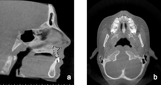
(a) The Anatomage area measurement tool was used to outline the premaxillary bone anterior to the premaxillary suture to form a closed polygon. The y and z coordinates of each vertex were recorded and used to calculate the maxillary sagittal centroid. (b) The axial slice through the z coordinate of the maxillary centroid that was calculated in the sagittal plane was viewed, and the Anatomage area measurement tool was used to outline a closed polygon. The x and y coordinates of each vertex were recorded and used to calculate the maxillary axial centroid.
The axial slice through the z coordinate of the maxillary centroid that was calculated in the sagittal plane was viewed, and the maxillary bone in the axial slice was used to define a second closed polygon. The anterior and posterior boundaries were defined by the alveolar bone, while lines tangent to the distal root surface of each maxillary lateral incisor served as the lateral borders. If the maxillary lateral root was not visible on the specific axial slice, a tangent to the mesial surface of each canine was used (Figure 1b). The x and y coordinates of each vertex were recorded as described previously to calculate the maxillary axial centroid. The x, y, and z coordinates of sagittal and axial centroids were averaged into one point and projected onto the midsagittal plane. This point served as the overall maxillary centroid.
Definition of mandibular centroid
The mandibular centroids were determined in a similar fashion as described previously. The midsagittal view was used to outline the visible mandibular symphysis to form a closed polygon (Figure 2a). The y and z coordinates of each vertex were recorded, and the mandibular sagittal centroid was calculated. The z coordinate of the mandibular sagittal centroid was used to view the axial slice, and the mandibular axial centroid was calculated based on the mandibular bone in the axial view. The anterior and posterior boundaries were defined by the alveolar bone and lines tangent to the distal surface of the lateral incisor root served as the lateral boundaries (Figure 2b). A line tangent to the mesial surface of the canine was used if the lateral incisor was not visible on the given axial slice. The x, y, and z coordinates of each centroid were averaged into one point and projected onto the midsagittal plane. This point served as the overall mandibular centroid.
Figure 2.
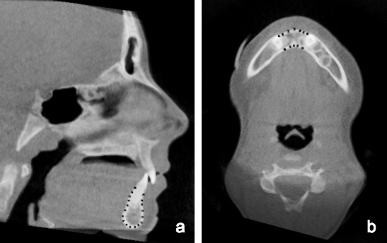
(a) The Anatomage area measurement tool was used to outline the visible mandibular symphysis to form a closed polygon. The y and z coordinates of each vertex were recorded and used to calculate the mandibular sagittal centroid. (b) The axial slice through the z coordinate of the mandibular centroid that was calculated in the sagittal plane was viewed, and the Anatomage area measurement tool was used to outline a closed polygon. The x and y coordinates of each vertex were recorded and used to calculate the mandibular axial centroid.
Development of a Novel anteroposterior Skeletal Analysis (M Measurement)
The overall maxillary and mandibular centroids were projected onto the midsagittal plane. True vertical lines were drawn from each centroid, and the linear distance between the two lines was measured along a true horizontal (Figure 3). If the overall maxillary centroid was anterior to the overall mandibular centroid, the measurement was positive; if the overall maxillary centroid was posterior to the overall mandibular centroid, the measurement was negative.
Figure 3.
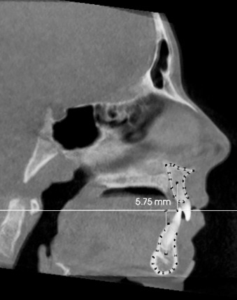
The overall maxillary and mandibular centroids were projected onto the midsagittal plane. True vertical lines were drawn from each centroid, and the linear distance between the two lines was calculated along the true horizontal (M measurement).
Standard lateral Cephalometric Analysis
Digital tracing and cephalometric analysis of the initial CBCT scans were performed. The ANB angle and anteroposterior dysplasia indicator (APDI)21 were measured.
The overall maxillary and mandibular centroid calculations, M measurement, and digital tracings were performed twice (T1 and T2) at least 2 weeks apart. A second examiner was trained in the methodology and performed all measurements on 30 randomly selected CBCT scans.
Statistical Analysis
A power analysis was performed using nQuery Advisor (version 7.0, Statistical Solutions, Boston, MA) with unequal sample groups; assuming an average difference between groups of 2.7° and a standard deviation of 2.1°,13 a sample size of at least 25 subjects with Class I skeletal pattern and 70 subjects with Class II skeletal pattern would provide more than 99% power for the study. The Kolmogorov-Smirnov test for each group and each measurement was >0.05, indicating normally distributed data. Mean measurements between groups were statistically analyzed with an independent samples t-test using SPSS version 19 (IBM Corp, Armonk, NY). Interexaminer and intraexaminer reliability were demonstrated using Bland/Altman22 and 3D scatterplots. The interexaminer and intraexaminer reliability of the average maxillary/mandibular centroid landmark was determined by calculating the 3D distance between the coordinates measured at T1 and T2, and T1 and TGK.
RESULTS
Descriptive data for linear and angular measurements are given in Table 1. Of the 100 subjects for whom CBCT scans were analyzed, 29 subjects were classified as having a Class I skeletal pattern and 71 subjects were classified as having a Class II skeletal pattern. In the Class I group, the average ANB was 1.77° (SD = 0.89°); the average APDI was 85.1° (SD = 3.63°); the average M measurement was 0.11 mm (SD = 1.83 mm). In the Class II group, the average ANB was 6.14° (SD = 1.94°); the average APDI was 77.4° (SD = 4.24°); the average M measurement was 4.57 mm (SD = 2.20 mm).
Table 1.
Mean Linear and Angular Measurements for Patients with Class I and Class II Malocclusion
The independent samples t-test for ANB, APDI, and the M measurement between the Class I and Class II groups were all significantly different (P < .001). Scatterplots for simple linear regression were created and are shown in Figures 4a and 4b. The correlation coefficients (r) between the M measurement and ANB and between the M measurement and APDI were 0.88 and −0.79, respectively (P < .001).
Figure 4.
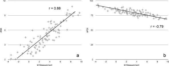
The M measurement for each patient was plotted against (a) the corresponding ANB angle and (b) against the APDI angle. The correlation coefficient (r) was calculated to be 0.88 and −0.79, respectively.
Bland and Altman scatterplots were used to visualize interexaminer and intraexaminer reliability for the M measurement by plotting the average value of the measurements taken at the two separate time points against the difference of values (Figure 5). 3D scatterplots for the maxillary and mandibular centroid landmarks were also created (Figure 6 and 7). The average interexaminer and intraexaminer 3D distance between the new landmark coordinates are given in Table 2. The mean 3D intraexaminer distance (T1-T2) between the maxillary and mandibular centroids was 0.76 ± 0.32 and 0.57 ± 0.39 mm, respectively. The mean 3D interexaminer distance (T1-TGK) between the maxillary and mandibular centroids was 0.89 ± 0.49 and 0.82 ± 0.43 mm, respectively.
Figure 5.
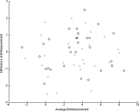
The average M measurement (mm) was plotted against the difference to demonstrate intraexaminer “o” (T1-T2) and interexaminer “x” (T1-TGK) reliability.
Figure 6.
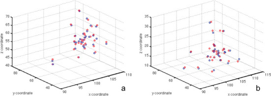
A three-dimensional scatterplot was used to visualize the intraexaminer reliability of (a) the average maxillary and (b) the average mandibular centroid. The blue circle represents T1; the red circle represents T2.
Figure 7.
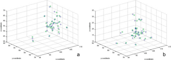
A three-dimensional scatterplot was used to visualize the interexaminer reliability of (a) the average maxillary and (b) the average mandibular centroid. The blue circle represents T1; the green circle represents TGK.
Table 2.
Average Interexaminer and Intraexaminer 3D Distance (mm) Between the Maxillary and Mandibular Centroid Landmark Coordinates Measured at T1-T2, and T1-TGK
DISCUSSION
The present study identified two novel landmarks and proposed an anteroposterior skeletal measurement based in three dimensions. The landmarks are an estimation of maxillary and mandibular basal bone23 and the anteroposterior measurement uses natural head position as a reference line, which is less influenced by external variables18,24 and provides a more stable reference for calculating skeletal discrepancies.
Cephalometric analysis of CBCT images has previously been explored. The recent literature has focused primarily on comparing measurements and landmark identification between traditional lateral cephalograms and lateral cephalograms generated from a CBCT scan. Angular and linear measurements on a reconstructed CBCT image were neither statistically nor clinically different from those measurements on a traditional lateral cephalogram.15,25 Interexaminer and intraexaminer reliability for landmark identification was high for both types of images.14,16,26 Other studies have gone beyond using two dimensionally based landmarks for CBCT analysis to determine transverse norms27 or outcomes of specific treatment.28 Both studies relied on dentoalveolar width measurements in the coronal plane at specific distances apical to the cementoenamel junction. The measurements, however, are based on individually defined point landmarks, which makes it difficult to compare data between the two studies.
Both the APDI and M measurement for patients with Class I skeletal pattern were statistically different from those measurements for patients with Class II skeletal pattern (P < .001), and they showed a high negative correlation coefficient (r = −0.79). Although the M measurement can potentially be used as a substitute for ANB and APDI when evaluating a patient's skeletal pattern, the measurement itself has limitations. The centroid locations are based on averages in the sagittal and axial planes, which makes landmark identification challenging. Furthermore, the tangent lines that serve as the lateral boundaries for axial centroid calculations are somewhat subjective. Advances in software algorithms and computer programming will inevitably simplify the identification process and provide practitioners with the ability to consistently and reliably analyze skeletal relationships in three dimensions.
The next step in the evolution of CBCT analysis is the creation of true three dimensionally based landmarks, volumes, and measurements. This study is the first to propose a systematic method for using 3D landmarks as the basis for a novel skeletal analysis that can be compared with the traditional 2D lateral cephalometric measurements. The M measurement itself has good interexaminer and intraexaminer reliability, as most of the linear measurements are within ± 2 mm of each other (Figure 5). The interexaminer reliability was less favorable and may be due to the complexity of landmark identification.
The reliability of the 3D landmarks can be visualized in Figures 6 and 7. The 3D scatterplots reveal very favorable interexaminer and intraexaminer reliability for both the maxillary and mandibular centroid landmarks, as the points are clustered together. Although the average interexaminer and intraexaminer 3D distance between the centroid landmark coordinates was small (Table 2), no other studies have evaluated the reproducibility of landmarks in three dimensions, and the results of this study could not be directly compared with the literature. The reliability of 3D landmarks should be addressed in future research.
The overall centroid landmarks and the M measurement itself combine 2D and 3D methods of imaging and can serve as a bridge for future studies and analyses that move away from linear and angular measurements and focus on areas and volumes of entire bony structures, such as the maxilla, mandible, and cranial floor, and their relationships in space. Other potential applications include transverse skeletal measurements using centroids as landmarks and center of volume analyses to assess maxillary and mandibular growth direction and effects of treatment. Imaging technology has progressed rapidly, and we must take advantage of this new information by reconsidering and questioning traditional methods of skeletal analysis.
CONCLUSIONS
This investigation identified new landmarks and a new measurement that can differentiate between Class I and Class II skeletal patterns and can serve as a potential substitute for ANB and APDI when a CBCT image is available.
True 3D analyses have the potential to shift how we diagnose and understand the effects of growth and treatment.
REFERENCES
- 1.Broadbent BH. A new x-ray technique and its application to orthodontia: the introduction of cephalometric radiography. Angle Orthod. 1981;51:93–114. [Google Scholar]
- 2.Baumrind S, Frantz RC. The reliability of head film measurements. 1. Landmark identification. Am J Orthod. 1971;60:111–127. doi: 10.1016/0002-9416(71)90028-5. [DOI] [PubMed] [Google Scholar]
- 3.Baumrind S, Frantz RC. The reliability of head film measurements. 2. Conventional angular and linear measures. Am J Orthod. 1971;60:505–517. doi: 10.1016/0002-9416(71)90116-3. [DOI] [PubMed] [Google Scholar]
- 4.Halazonetis DJ. Cone-beam computed tomography is not the imaging technique of choice for comprehensive orthodontic assessment. Am J Orthod Dentofacial Orthop. 2012;141:403–405–407. doi: 10.1016/j.ajodo.2012.02.010. [DOI] [PubMed] [Google Scholar]
- 5.Kapila S, Conley RS, Harrell WE. The current status of cone beam computed tomography imaging in orthodontics. Dentomaxillofac Radiol. 2010;40:24–34. doi: 10.1259/dmfr/12615645. [DOI] [PMC free article] [PubMed] [Google Scholar]
- 6.Grünheid T, Kolbeck Schieck JR, Pliska BT, Ahmad M, Larson BE. Dosimetry of a cone-beam computed tomography machine compared with a digital x-ray machine in orthodontic imaging. Am J Orthod Dentofacial Orthop. 2012;141:436–443. doi: 10.1016/j.ajodo.2011.10.024. [DOI] [PubMed] [Google Scholar]
- 7.Ludlow J. Dosimetry of 3 CBCT devices for oral and maxillofacial radiology: CB Mercuray, NewTom 3G and i-CAT. Dentomaxillofac Radiol. 2006;35:219–226. doi: 10.1259/dmfr/14340323. [DOI] [PubMed] [Google Scholar]
- 8.Ludlow JB, Ivanovic M. Comparative dosimetry of dental CBCT devices and 64-slice CT for oral and maxillofacial radiology. Oral Surg Oral Med Oral Pathol Oral Radiol Endod. 2008;106:106–114. doi: 10.1016/j.tripleo.2008.03.018. [DOI] [PubMed] [Google Scholar]
- 9.Silva MAG, Wolf U, Heinicke F, Bumann A, Visser H, Hirsch E. Cone-beam computed tomography for routine orthodontic treatment planning: a radiation dose evaluation. Am J Orthod Dentofacial Orthop. 2008;133:640.e1–640.e5. doi: 10.1016/j.ajodo.2007.11.019. [DOI] [PubMed] [Google Scholar]
- 10.Periago DR, Scarfe WC, Moshiri M, et al. Linear accuracy and reliability of cone beam CT derived 3-dimensional images constructed using an orthodontic volumetric rendering program. Angle Orthod. 2008;78:387–395. doi: 10.2319/122106-52.1. [DOI] [PubMed] [Google Scholar]
- 11.Brown AA, Scarfe WC, Scheetz JP, et al. Linear accuracy of cone beam CT derived 3D images. Angle Orthod. 2009;79:150–157. doi: 10.2319/122407-599.1. [DOI] [PubMed] [Google Scholar]
- 12.Berco M, Rigali PH, Jr, Miner RM. et al. Accuracy and reliability of linear cephalometric measurements from cone-beam computed tomography scans of a dry human skull. Am J Orthod Dentofacial Orthop. 2009;136:17.e1–17.e9. doi: 10.1016/j.ajodo.2008.08.021. [DOI] [PubMed] [Google Scholar]
- 13.Ludlow JB, Gubler M, Cevidanes L, Mol A. Precision of cephalometric landmark identification: cone-beam computed tomography vs conventional cephalometric views. Am J Orthod Dentofacial Orthop. 2009;136:312.e1–312.e10. doi: 10.1016/j.ajodo.2008.12.018. [DOI] [PMC free article] [PubMed] [Google Scholar]
- 14.Lagravere MO, Low C, Flores-Mir C, et al. Intraexaminer and interexaminer reliabilities of landmark identification on digitized lateral cephalograms and formatted 3-dimensional cone-beam computerized tomography images. Am J Orthod Dentofacial Orthop. 2010;137:598–604. doi: 10.1016/j.ajodo.2008.07.018. [DOI] [PubMed] [Google Scholar]
- 15.Oz U, Orhan K, Abe N. Comparison of linear and angular measurements using two-dimensional conventional methods and three-dimensional cone beam CT images reconstructed from a volumetric rendering program in vivo. Dentomaxillofac Radiol. 2011;40:492–500. doi: 10.1259/dmfr/15644321. [DOI] [PMC free article] [PubMed] [Google Scholar]
- 16.Chang Z-C, Hu F-C, Lai E, Yao C-C, Chen M-H, Chen Y-J. Landmark identification errors on cone-beam computed tomography-derived cephalograms and conventional digital cephalograms. Am J Orthod Dentofacial Orthop. 2011;140:e289–e297. doi: 10.1016/j.ajodo.2011.06.024. [DOI] [PubMed] [Google Scholar]
- 17.Stahl F, Baccetti T, Franchi L, McNamara JA., Jr Longitudinal growth changes in untreated subjects with Class II Division 1 malocclusion. Am J Orthod Dentofacial Orthop. 2008;134:125–137. doi: 10.1016/j.ajodo.2006.06.028. [DOI] [PubMed] [Google Scholar]
- 18.Lundström F, Lundström A. Natural head position as a basis for cephalometric analysis. Am J Orthod. 1992;101:244–247. doi: 10.1016/0889-5406(92)70093-P. [DOI] [PubMed] [Google Scholar]
- 19.Lundström A, Lundström F, Lebret LML, Moorrees CFA. Natural head position and natural head orientation: basic considerations in cephalometric analysis and research. Eur J Orthod. 1995;17:111–120. doi: 10.1093/ejo/17.2.111. [DOI] [PubMed] [Google Scholar]
- 20.Bourke P. Calculating the Area and Centroid of a Polygon. http://local.wasp.uwa.edu.au/‐pbourke/geometry/polyarea (1988), Access date 11/12/2013. [Google Scholar]
- 21.Kim YH, Vietas JJ. Anteroposterior dysplasia indicator: an adjunct to cephalometric differential diagnosis. Am J Orthod. 1978;73:619–633. doi: 10.1016/0002-9416(78)90223-3. [DOI] [PubMed] [Google Scholar]
- 22.Bland JM, Altman DG. Statistical methods for assessing agreement between two methods of clinical measurement. Lancet. 1986;1:307–310. [PubMed] [Google Scholar]
- 23.Ball RL, Miner RM, Will LA, Arai K. Comparison of dental and apical base arch forms in Class II Division 1 and Class I malocclusions. Am J Orthod Dentofacial Orthop. 2010;138:41–50. doi: 10.1016/j.ajodo.2008.11.026. [DOI] [PubMed] [Google Scholar]
- 24.Madsen DP, Sampson WJ, Townsend GC. Craniofacial reference plane variation and natural head position. Eur J Orthod. 2008;30:532–540. doi: 10.1093/ejo/cjn031. [DOI] [PubMed] [Google Scholar]
- 25.Gribel BF, Gribel MN, Frazão DC, McNamara JA, Jr, Manzi FR. Accuracy and reliability of craniometric measurements on lateral cephalometry and 3D measurements on CBCT scans. Angle Orthod. 2011;81:26–35. doi: 10.2319/032210-166.1. [DOI] [PMC free article] [PubMed] [Google Scholar]
- 26.Ludlow JB, Gubler M, Cevidanes L, Mol A. Precision of cephalometric landmark identification: cone-beam computed tomography vs conventional cephalometric views. Am J Orthod Dentofacial Orthop. 2009;136:312.e1–312.e10. doi: 10.1016/j.ajodo.2008.12.018. [DOI] [PMC free article] [PubMed] [Google Scholar]
- 27.Miner RM, Al Quabandi S, Rigali PH, Will LA. Cone-beam computed tomography transverse analysis. Part 1: normative data. Am J Orthod Dentofacial Orthop. 2012;142:300–307. doi: 10.1016/j.ajodo.2012.04.014. [DOI] [PubMed] [Google Scholar]
- 28.Tai K, Park JH, Mishima K, Shin JW. 3-dimensional cone-beam computed tomography analysis of transverse changes with Schwarz appliances on both jaws. Angle Orthod. 2011;81:670–677. doi: 10.2319/110910-655.1. [DOI] [PMC free article] [PubMed] [Google Scholar]


