Abstract
The field of tissue engineering and regenerative medicine will tremendously benefit from the development of three dimensional scaffolds with defined micro- and macro-architecture that replicate the geometry and chemical composition of native tissues. The current report describes a freeform fabrication technique that permits the development of nerve regeneration scaffolds with precisely engineered architecture that mimics that of native nerve, using the native extracellular matrix component hyaluronic acid (HA). To demonstrate the flexibility of the fabrication system, scaffolds exhibiting different geometries with varying pore shapes, sizes and controlled degradability were fabricated in a layer-by-layer fashion. To promote cell adhesion, scaffolds were covalently functionalized with laminin. This approach offers tremendous spatio-temporal flexibility to create architecturally complex structures such as scaffolds with branched tubes to mimic branched nerves at a plexus. We further demonstrate the ability to create bidirectional gradients within the microfabricated nerve conduits. We believe that combining the biological properties of HA with precise three dimensional micro-architecture could offer a useful platform for the development of a wide range of bioartificial organs.
Introduction
Nerve guidance scaffolds are traditionally tubular structures that are developed to bridge the gap of a severed nerve, thereby serving to physically restrict (“guide”) regenerating axons and to minimize the in-growth of scar tissue. A number of natural (vein, collagen, and chitosan) and synthetic materials (silicone, poly(glycolide) (PGA), and poly(hydroxbutyrate)) have been researched as scaffolds (Belkas et al., 2004; Bellamkonda, 2006; Strauch, 2000). Physical nerve guidance by a scaffold having simpler architecture may, however, not be sufficient to promote structural and functional recovery, especially in the case of longer nerve gaps. Additionally, there is a need to fabricate designer scaffolds with complex architectures (e.g., branches) to be utilized for more complicated nerve injuries (e.g., injury between the proximal stump of the common digital nerve and the two distal stumps of the proper digital nerve). Furthermore, design parameters of the scaffold should also include native extracellular matrix (ECM) components, which can provide functional cues to the resident cells and thus can aid in regeneration.
Freeform fabrication has gained tremendous attention recently in the bioengineering field because of its ability to create three dimensional (3D) scaffolds with defined architecture mimicking the native tissue microenvironment (Hollister, 2005; Mondrinos et al., 2006; Sachlos and Czernuszka, 2003). This fabrication technique can be used to fabricate micro-length scale features that can interact with cells and ECM components in a more biomimetic manner and therefore can enhance major cell functions such as adhesion, migration, and proliferation (Chen et al., 2010; Han et al., 2008; Lu et al., 2006). Furthermore, solid freeform fabrication also provides the ability to create 3D scaffolds with spatially controlled properties (e.g., localized microenvironments of various growth factors and/or cell adhesive proteins, which may further enhance cell growth and tissue recovery). This technique offers the ability to fabricate 3D scaffolds that are patient specific and can match precisely to a particular defect site.
In the current study, we describe the fabrication and characterization of 3D scaffolds of hyaluronic acid (HA) for neural tissue repair applications. The freeform fabrication technique employed in the current report is a digital micro-mirror-array device (DMD), which unlike the traditional, point-by-point scanning 3D-stereolithorgraphy techniques, creates the structure in a layer-wise fashion by fabricating the entire layer simultaneously (Chen, et al., 2010; Han, et al., 2008; Lu, et al., 2006). The required 3D shape is first split into a series of 2D cross-sectional images. These images are then projected sequentially by the micro-mirror-array of the DMD system onto the photocurable liquid, creating a single layer at a time.
HA is a naturally occurring, nonimmunogenic bio-polymer and has been used extensively for tissue engineering applications (Agerup et al., 2005; Ikeda et al., 2003; Jiang et al., 2007; Ozgenel, 2003; Yoo et al., 2005). It is a glycosaminoglycan composed of repeating disaccharide units of D-glucuronic acid and N-acetylglucosamine, and is naturally present in ECM where it is responsible for maintaining tissue homeostasis (Leach and Schmidt, 2004). HA scaffolds offer a porous, hydrated environment through which small molecules diffuse. HA is important in wound healing, and application of exogenous HA can reduce scar formation and promote regeneration in peripheral nerve injuries (Chen and Abatangelo, 1999; Ikeda, et al., 2003). Unmodified HA hydrogels are essentially non-adhesive to cells, but when modified with appropriate cell-adhesive proteins and peptides, they can provide signals to enhance cell attachment and migration (Leach and Schmidt, 2004).
In this paper, 3D microfabricated scaffolds of HA were designed with micron-scale feature sizes exhibiting varying geometries and pore sizes. The novelty of the fabrication system was illustrated by creating architecturally complex soft tissue engineering scaffolds (i.e., branched nerves from native ECM substrates). Scaffolds of HA were completely degradable in hyaluronidase. Further, HA constructs were covalently functionalized with the cell-adhesive protein, laminin to render them cell adhesive. The cell-compatible fabrication method also provides opportunities to incorporate gradients of bioactive molecules.
Materials and Methods
Materials
Sodium hyaluronate of molecular weight 3.5×10⁴ Da was obtained from Lifecore Biomedical (Chaska, MN). Photoinitiator Irgacure 2959 (I2959) was obtained from Ciba Specialty Chemicals (Basel, Switzerland). Fluorescent microparticles were obtained from Molecular Probes (Eugene, OR). HA-binding protein (HAbp) was obtained from Calbiochem. Hyaluronidase (500 U/ml) was purchased from Sigma-Aldrich. Zinc acrylate and 2,2,6,6-Tetramethyl-piperidin-1-oxyl (TEMPO, free-radical quencher) were purchased from Sigma-Aldrich. All other chemicals were obtained from Sigma-Aldrich.
Synthesis of Glycidyl Methacrylate Modified Hyaluronic Acid (GMHA)
Photopolymerizable methacrylate groups were attached to HA by a method described previously (Suri and Schmidt, 2009). Briefly, a 1% w/v solution of hyaluronic acid was prepared in 50:50 water:acetone by stirring overnight. Triethylamine and glycidyl methacrylate were added to the HA solution in twenty-fold molar excess and stirred overnight at room temperature. HA solution was dialyzed (MW cut off 3500, Spectrum Lab., San Fransisco, CA) against deionized water for 48 hrs and lyophilized. The lyophilized GMHA was desiccated, and stored at −20°C in the dark until use.
Nerve Conduit Fabrication: Setup of DMD Fabrication System
The fabrication system (Figure 1) includes a servo-stage (CMA-25-CCCL & ESP300, Newport), three syringe pumps, a glass window, a DMD system (Discovery 1100, Texas Instruments), a UV lamp (200W, S2000, EXFO), and a UV-grade projection lens (Edmond Optics). The three syringe pumps inject two types of HA pre-polymers and PBS solution to an outlet on the servo-stage. The DMD chip is composed of an array (1024 by 768) of micro-mirrors that form reflective patterns. These micro-mirrors are illuminated by the UV light from the lamp using an 8 mm light guide. Upon illumination, the UV images of the reflective patterns are projected onto the photo-curable monomer by the projection lens. The pre-polymer solution, loaded above the servo-stage, is selectively cured by the modulated UV light to form each scaffold layer.
Figure 1.
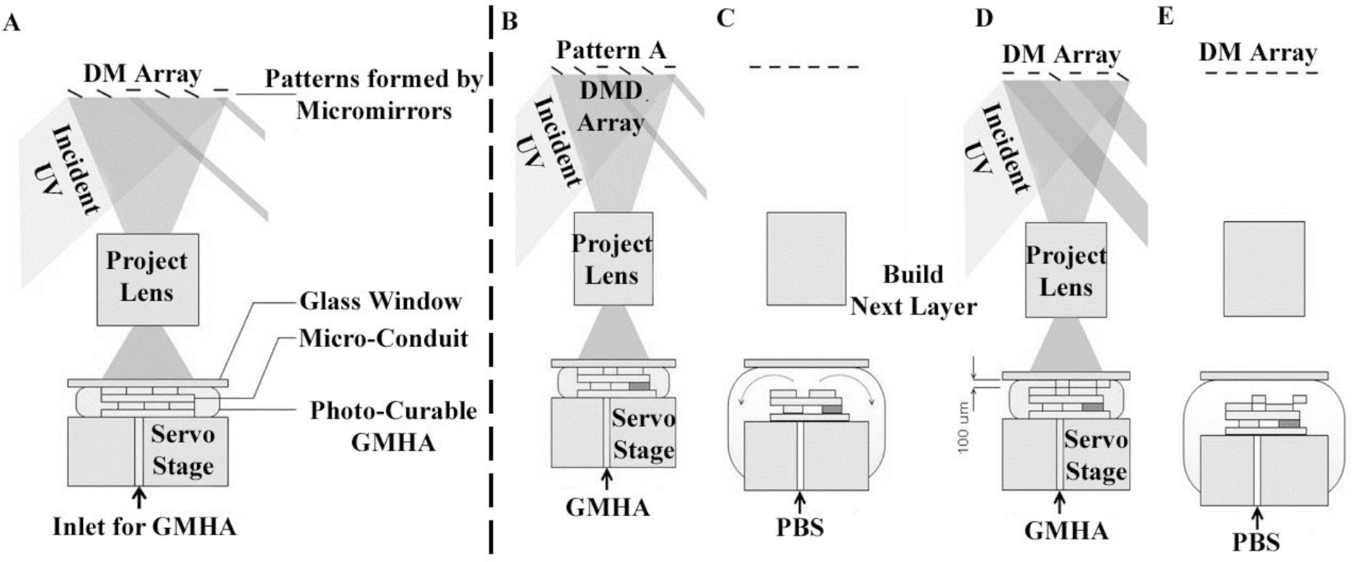
Fabrication process using the DMD microfabrication system. (A) Schematic of the DMD microfabrication system for the layer-by-layer fabrication of scaffolds. After fabricating a layer (B), the stage moves down 0.5 mm and pulls the structure away from the glass window. After the curing process, PBS is pumped into the gap to rinse away any partially polymerized GMHA (C). To build a new layer above the just-formed structure after the rinsing step (D), the stage is moved to bring the just-formed layer 200 μm below the glass slide. Fresh monomer is pumped into the 200 μm gap, and the next layer is then created by UV curing followed by PBS purging again (E).
The glass window is located at the focal point of the projection lens and remains above the scaffold during the fabrication process. Before UV exposure, the GMHA pre-polymer solution is pumped to fill the space between the window and the scaffold, which controls the thickness of the scaffold layers. Upon UV illumination, the GMHA solution below the window is cured selectively, resembling the pattern of the micro-mirror array. The window is coated with (tridecafluoro-1,1,2,2-tetrahydrooctyl) trichlorosilane, a low-surface-tension agent that releases the scaffold from the window surface after UV curing. The coating for the glass window is reported elsewhere (Junarsa and Nealey, 2004). The servo-stage, the DMD system, and the UV lamp are connected to a personal computer and are controlled by computer program.
Preparation of Photo-curable GMHA Pre-polymer
To prepare the photo-curable GMHA pre-polymer, 1 wt% of Irgacure 2959 and 0.01 wt% of TEMPO were added to a 10 wt% aqueous solution of GMHA. The GMHA was also loaded with 10 wt% of zinc acrylate to enhance rigidity.
Scaffold Fabrication Process
The fabrication process using the DMD system is shown in Figure 2. The servo-stage was positioned 200 μm below the glass window in the beginning of the fabrication process. The GMHA was pumped from the stage outlet into the gap between the window and the servo-stage. The power of the UV image was determined to be ~8 mW/cm2. The exposure time of the UV pattern for each layer was 30 seconds. After the first layer was fabricated (Figure 2A, B), the stage moved downward 0.5 mm and pulled the structure away from the glass window, which released the structure because of low surface energy of the fluoride coating. After the curing process, PBS was pumped into the gap to rinse away any partially polymerized GMHA, which otherwise may solidify and block the scaffold-pores in following exposures. The rinsed PBS was aspirated through the conduit back into the PBS-syringe-pump.
Figure 2.
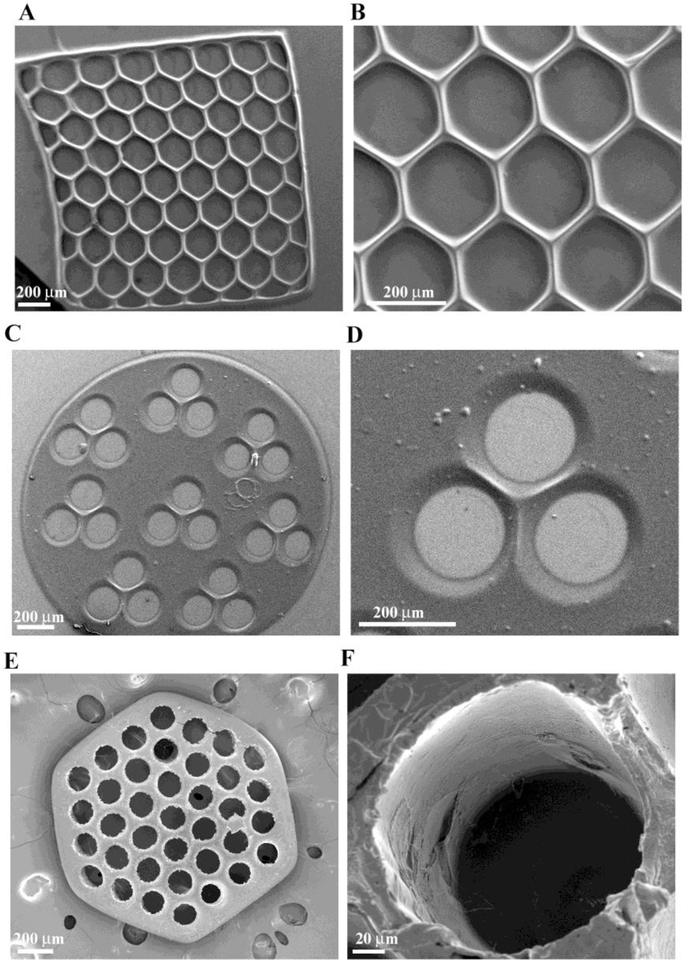
SEM micrograph of single-layered scaffolds of GMHA with intricate pore geometries, (A) and (B) hexagonal patterns, (C) and (D) circular patterns with three channels, (E) and (F) circular patterns with more than 30 channels created using the DMD microfabrication system.
To build the next layer above the previously formed layer (Figure 2C, D), the stage was moved so that there was a gap of 200 μm between the previous layer and the glass slide. Fresh monomer was pumped into the 200 μm gap, and the next layer was then created by UV curing. A 3D scaffold was created by repeating the layer-by-layer fabrication procedure. By using the same DMD image for the fabrication of each image, we created a multi-channel HA conduit. More complicated geometries such as a three-branched conduit were also fabricated by using thirty-two different cross-sectional images in a sequence. A heterogeneous scaffold with spatial variation in the properties (i.e., a gradient scaffold) was also created by changing the composition of the prepolymer solution during the fabrication process, as detailed in the section describing gradient scaffold fabrication.
Single Layered Conduit Morphology
The morphology of single-layered scaffolds was imaged using scanning electron microscopy (SEM). For SEM studies, the constructs were fixed by adding 3% glutaraldehyde solution in 0.1 M cacodylate buffer for 3 hrs. Post fixation, scaffolds were washed with PBS three times for 15 min each. The gels were dehydrated by incubating with graded ethanol solutions (30, 50, 70, 85, 90, 95, and 100% for 1 hr each). The final dehydration step was performed by adding hexamethyl disilazine (HMDS) and drying in a fumehood for 2 hrs. Dried hydrogels were coated with Pt/Pd using a sputter coater (Cressington 208 HR) and imaged using SEM (Zeiss SUPRA 40 VP).
Biological Activity of HA after Conduit Fabrication
To assess the bioactivity of HA after UV crosslinking, the scaffolds were (1) incubated with biotinylated-HA-binding protein (b-HAbp) (Sigma Aldrich) overnight at 4°C (2) rinsed in PBS, pH 7.4 to remove unbound b-HAbp, and (3) incubated with Cyt3-Streptavidin (Zymed, San Francisco, CA), which binds specifically to the biotin moiety of b-HAbp. The negative control was treated in the same way but was not incubated with b-HAbp.
In Vitro Conduit Degradation
In vitro degradation was studied in the presence of hyaluronidase (hyase; Sigma). 600 μm thick hydrogel constructs were pre-swollen in PBS overnight. Scaffold degradation was performed in 500 U/ml of hyase in PBS (pH 7.4). At regular time points the scaffolds were imaged using phase contrast microscopy to obtain images of degrading scaffolds.
Modification of Conduit Surface with Cell-adhesive Proteins
HA and its hydrogel derivatives are inherently non cell-adhesive; so a key challenge is to modify the scaffolds to make them cell adhesive. We accomplished this by grafting the cell adhesive protein, laminin, on the surface of the scaffolds using 1-ethyl-3-[3-dimethylaminopropyl]carbodiimide hydrochloride / N-hydroxysulfosuccinimide EDC/sulfo-NHS (Pierce Biotechnology Inc.) chemistry. After fabrication, the scaffolds were incubated with 1% EDC/NHS solution for 2 hrs for activation of the carboxylic groups. Following this, the scaffolds were incubated with 100 μg/ml laminin solution for 48 hrs at 4°C. Covalent immobilization of laminin was visualized by immunostaining with rabbit anti-laminin antibody and Alexa Fluor 546 goat anti-rabbit IgM (Invitrogen). Briefly, the scaffolds were blocked in 5% goat serum and 0.3% triton X-100 in PBS for 1 hr followed by incubation with rabbit anti-laminin primary antibody (1:200; Sigma) in blocking buffer overnight at 4°C. The unbound antibody was washed from the scaffold with several PBS washes, and the secondary antibody (Alexa Fluor conjugated, 1:500; Invitrogen) was added and incubated with the scaffolds for 1 hr followed by several PBS rinses. The scaffolds were imaged using confocal fluorescence microscopy (Leica TCS SP2 AOBS, Wetziar, Germany) and epifluorescence microscopy. The negative control scaffolds were not activated with EDC/NHS but treated with the laminin in the same manner.
Cell Culture
Schwann cells were harvested as described previously (Kleitman et al., 1991) and cultured with DMEM (Invitrogen, Carlsbad CA) supplemented with 10% fetal bovine serum (Hyclone, Rockford IL), 2 μM forskolin, 30 μg ml−1 bovine pituitary extract (BD Biosciences, Sparks MD), and 1% penicillin–streptomycin–amphotericin (Sigma). The cells were maintained in standard TCPS tissue culture dishes coated with poly-L-lysine (PLL) and passaged 1:6 when the cells reached 70% confluency.
Cell Adhesion
Cells were seeded on the top surface of the scaffolds and cultured for 24 hrs in cell culture medium before viability was analyzed using a Live/Dead® viability/cytotoxicity kit. To stain the cells, old medium was aspirated and cells were incubated with 2 μM of calcein AM and 4 μM of ethidium homodimer in PBS for 20 min in the dark at 37°C. Live cells have intracellular esterase activity and are stained green with calcein, whereas ethidium enters the dead cells through damaged membrane and becomes integrated in the DNA, staining the cells red. In the case of the multilayered branched scaffold, the scaffold was placed in an upright position on a non-cell adherent surface (parafilm), and the cell suspension was introduced inside the lumens. The cells were allowed to adhere to the scaffolds for 4 hrs. Following this, the remaining cell solution was aspirated and the scaffolds were covered in culture medium.
To perform immunostaining of Schwann cells on the scaffolds, the scaffolds were fixed in 4% paraformaldehyde (Sigma) in PBS for 20 min followed by three washes in PBS. The cells were blocked in 5% goat serum and 0.3% triton X-100 in PBS for 1 hr followed by overnight incubation with primary antibody (rabbit-anti S100, 1:200, Dako Corporation, Carpinteria CA) in blocking buffer (0.3% Triton X-100 and 5% goat serum in PBS) at 4°C. Scaffolds were washed in PBS to eliminate any unbound primary antibody. Secondary antibodies conjugated to Alexa Fluor dyes were purchased from Invitrogen (Carlsbad CA) and were used at a dilution of 1:500 in PBS for 1 hr at room temperature. The cells were imaged with a fluorescence microscope (IX-70, Olympus, Center Valley, PA) and the images were captured using a color CCD camera (Optronics MagnaFire, Goleta, CA).
Creation of Immobilized Gradient in Conduit
To demonstrate “proof-of-concept” and to visualize the feasibility of gradient formation using our DMD microfabrication system, we created gradients of fluorescent microspheres. Fluorescently-labeled microparticles (Cyt-5 labeled, FITC labeled, 1 μm, Molecular Probes, Eugene, OR) were mixed into the GMHA solution at a concentration of 1% (vol/vol) and the prepolymer solution was polymerized to create a gradient, which was analyzed using fluorescence microscopy. To better visualize the gradient, a solid cylindrical scaffold without channels was fabricated, since the presence of channels may interfere with the visualization of gradient fluorescence.
Results and Discussion
Solid Freeform Fabrication of Scaffolds and Structural Morphology
Hyaluronic acid scaffolds were fabricated using a DMD microfabrication system that consists of a computer-controlled servo-stage with an automated z axis. Scaffolds were created using layer-by-layer manufacturing and UV crosslinking, such that the prepolymer solution underwent rapid solidification after UV exposure (Figure 1). The patterned scaffolds were fabricated exhibiting different geometries (i.e., circles, hexagons, squares) with varying pore shapes and sizes. The structure and surface morphology of the single-layered scaffolds was investigated by scanning electron microscopy (SEM). Figure 2 represents patterned scaffolds of photocrosslinked glycidyl-methacrylate modified HA (GMHA) with varying geometries. The dimensions and geometry of the scaffold pores and channels were controlled by altering the image projected onto the DMD micromirrors, which in turn alters the UV light falling onto the GMHA solution. Single-layered scaffolds with precise internal features and pore sizes were created by a single 30 sec UV exposure. Scaffolds with hexagonal (Figure 2A–B) and circular (Figure 2C–F) geometries exhibiting hexagonal and circular pores with pore sizes of ~100 μm to 200 μm were fabricated. The figure also depicts that the change in geometry does not affect the feature resolution once the fabrication parameters have been optimized.
The DMD microfabrication process is associated with some challenges such as light scattering and deep UV penetration. Deep UV penetration may affect the previously-formed layers by the current photo-pattern being displayed, resulting in over curing. UV light scattering by the previously formed layers may polymerize the monomer solution within the previous layers, resulting in formation of oligomers that may block the pores of the scaffold and result in loss of resolution (Han, et al., 2008). Light scattering can also interfere with formation of new layers. To overcome these barriers, we successfully adjusted the curing depth of monomer to about 200 μm (thickness of the single layer) and minimized the scattering effect by adding the free-radical quencher, 2,2,6,6-tetramethylpiperidine 1-oxyl (TEMPO). Bright-field microscopy revealed that the geometry of each of the honeycomb layers was clearly defined, and the pores of the honeycomb structures were free from undesired polymerization or oligomer accumulation after addition of free-radical quencher (Figure 3). To further improve the resolution and to prevent the accumulation of oligomers (i.e., partially crosslinked monomers in the previously formed layers), we purged the scaffolds with PBS solution after formation of each layer during the fabrication.
Figure 3.
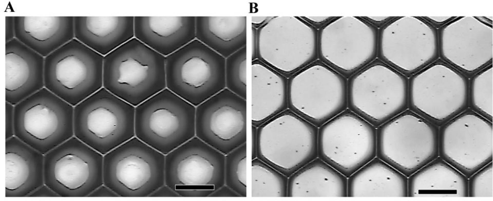
(A) Photopatterned single-layered GMHA scaffold on a glass slide. The pores of a honeycomb structure are sealed by unwanted curing caused by scattered light. (B) Patterning the same monomer with the addition of the UV dye TEMPO at a concentration of 0.05 wt%. The geometry of the honeycomb structure has increased feature resolution. (Scale bars, 200 μm)
Biological Activity of HA is Retained in Fabricated Scaffolds
The biological functions of HA (i.e., cell migration, proliferation, activation of immune response) are associated with the binding of HA with native HA binding proteins (Fieber et al., 1999; Slevin et al., 2002). Thus it is essential that in the process of chemical modification and UV fabrication, HA retains its biologically-active form. A protein binding immunostaining assay was performed to assess the biological activity of HA after the conduit fabrication. HA-binding protein assay has been performed previously to assess the biological activity of HA (Cen et al., 2002; Collier et al., 2000). Single-layered scaffolds were incubated with biotinylated-HAbp and then stained for Cyt3-streptavidin. Immunofluorescence microscopy of HA conduits indicate binding of HA with HAbp after UV fabrication (Figure 4 A–C represent top, middle, and bottom of the scaffold, respectively) as compared to the negative control that was not incubated with HAbp (Figure 4D). These findings confirm that HA retained its biological activity after the fabrication process.
Figure 4.
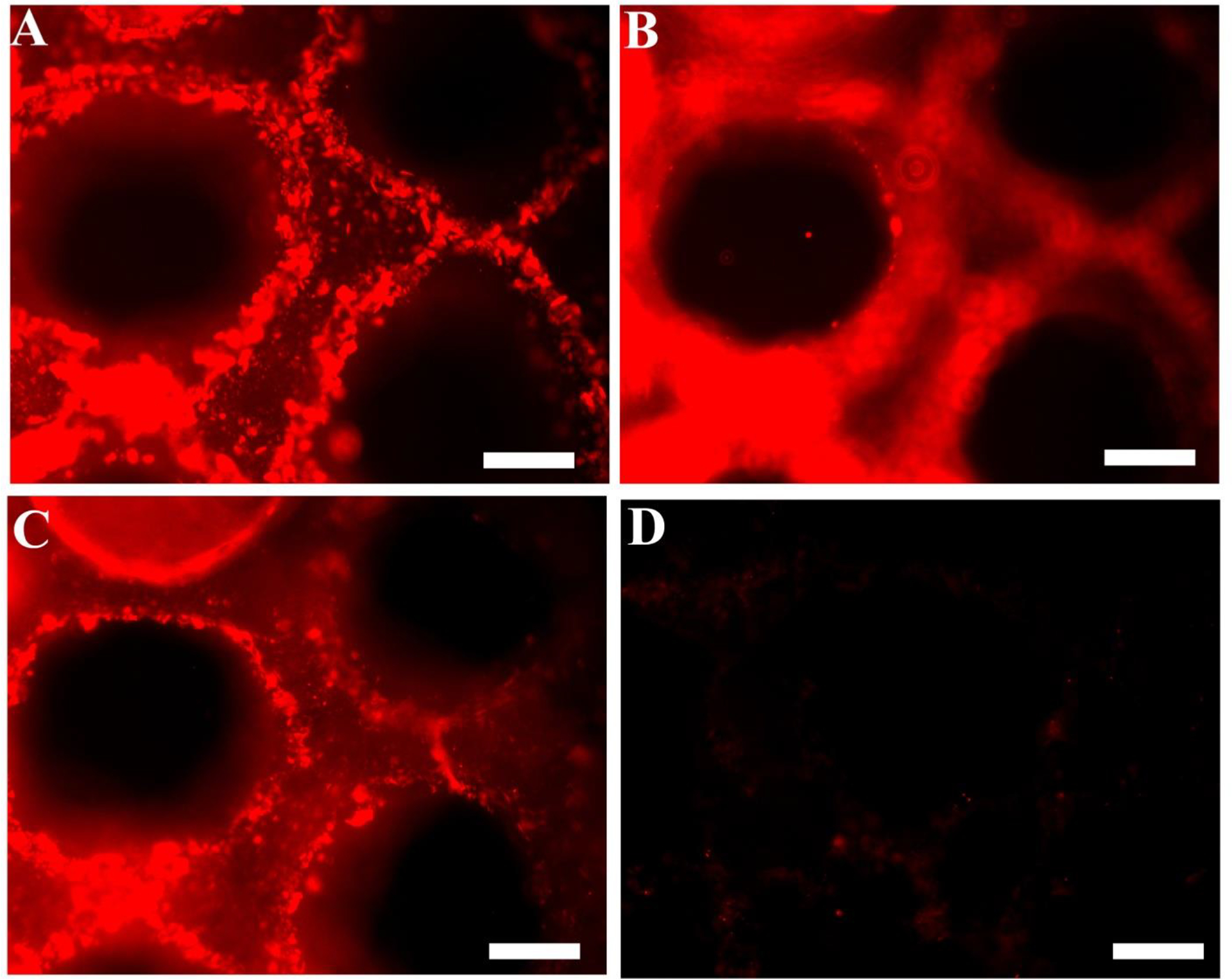
Fluorescence micrographs showing the scaffold stained for HA. Micrographs clearly demonstrate that the scaffolds bind to HA binding protein (HAbp), suggesting the retention of native HA bioactivity. Biotinylated-HAbp and Cyt3-streptavidin were used to stain the microfabricated scaffolds. (A), (B) and (C) demonstrate the top, middle, and bottom view of the scaffold indicating that the HA retains its biological activity after the fabrication process. The scaffold illustrated in (D) was not incubated with b-HAbp and shows no fluorescence (negative control). (Scale bars, 200 μm)
Scaffold Degradation
HA-based scaffolds with a thickness of 600 μm were fabricated using two different UV exposure times: 25 seconds and 40 seconds. These scaffolds were degraded in 500 U/ml of hyaluronidase (hyase; Sigma) and were imaged at different time points to obtain degradation profiles (Figure 5). Longer UV exposure times resulted in slower degradation of the scaffolds, which can be attributed to the higher crosslinking density within the scaffolds. Further, with degradation, the hydrogels began losing their structural integrity and shape. All of the hydrogels were completely degraded with prolonged exposure to the enzyme, indicating that the microfabricated HA scaffolds retain the native enzymatic biodegradability by hyase. These results are in agreement with the retention of biological activity of the scaffolds as demonstrated earlier.
Figure 5.
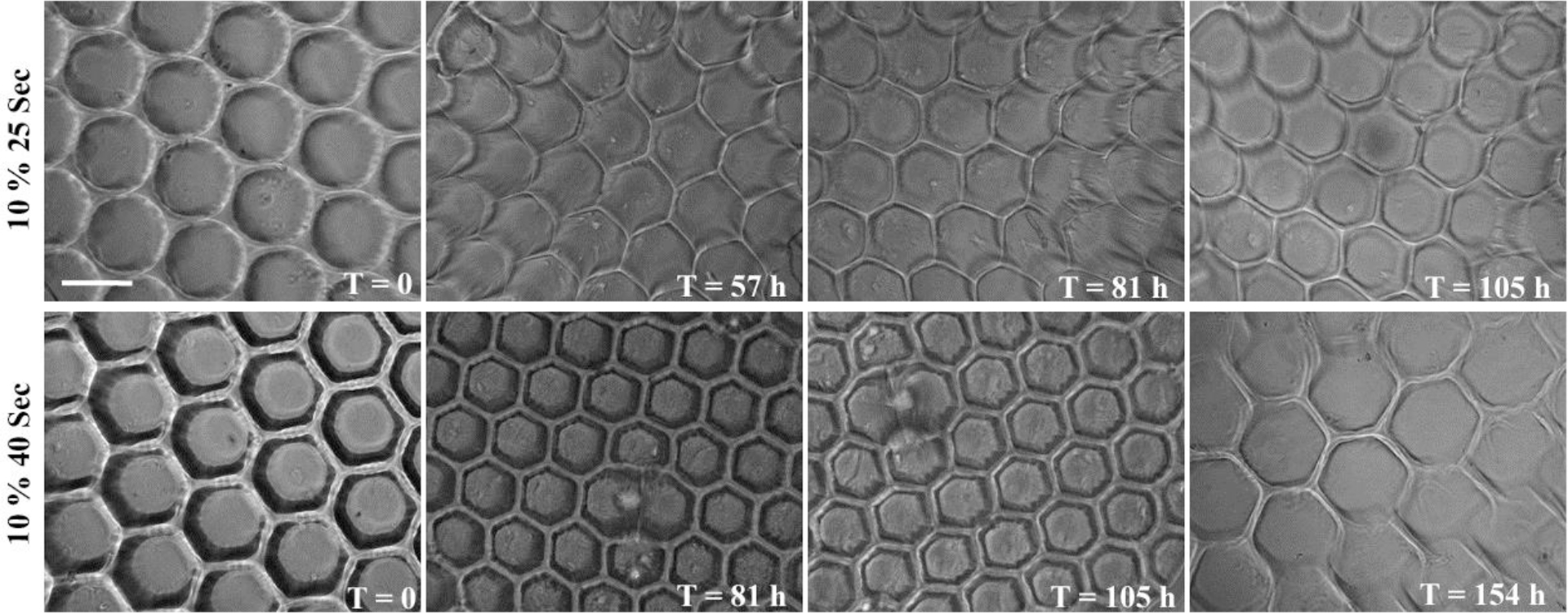
Phase contrast micrographs of HA scaffolds demonstrating enzymatic degradation in 500 U/ml hyaluronidase at different time points. Scaffolds fabricated with two different exposure times had varying degrees of crosslinking density resulting in varying degradation rates. Scaffolds lost their structural integrity with time (unit: hours) and were completely degraded after the last time point captured for each sample. (Scale bar, 200 μm)
Fabricated Scaffolds Support Cell Adhesion
HA and its hydrogel derivatives are inherently non cell-adhesive; thus, it was essential to functionalize the freeform fabricated scaffolds with cell binding proteins to render them cell adhesive. This was accomplished by covalently grafting laminin on the surface of the scaffolds using EDC/NHS chemistry. Covalent immobilization of laminin was visualized by immunostaining of laminin (Figure 6A). As shown, laminin was successfully and uniformly conjugated to the surface of the scaffolds. Further, Schwann cells, as a model neuronal cell, were seeded on the surface of single-layered laminin-modified HA scaffolds to assess the cell adhesion and cytocompatibility of patterned HA scaffolds. Schwann cells not only adhered to the laminin-functionalized HA scaffolds but also retained their viability for at least 36 hrs (Figure 6B). Schwann cells failed to adhere to HA scaffolds that were not functionalized with laminin (Figure 6C). S100 staining of the Schwann cells further indicated that the adhered cells lined the walls of the scaffold and underwent normal spreading (Figure 6D).
Figure 6.
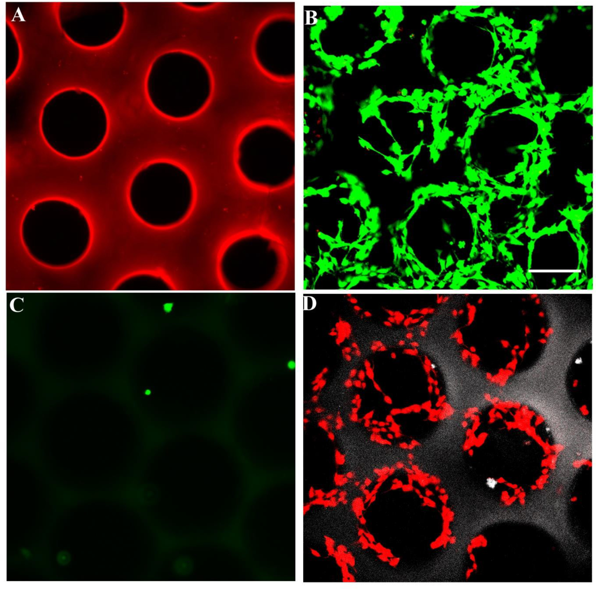
(A) Laminin was covalently conjugated to scaffold surfaces. Fluorescence micrographs show scaffolds immunostained for laminin. (B) Schwann cells seeded on laminin-modified HA scaffolds adhered and remained viable for 36 hrs after cell seeding, whereas cells did not adhere to the unmodified scaffold (C). Live cells were stained green with 2 μM of calcein and dead cells were stained red with 4 μM of ethidium bromide. (D) Schwann cells were stained for S100 protein on the scaffold. S100 staining indicates that the adhered cells lined the walls of the scaffold and underwent spreading (Scale bar, 150 μm)
Three-dimensional Scaffolds for Nerve Regeneration
After fabricating the single-layered scaffolds with varying geometries and pore sizes, we fabricated designer 3D scaffolds. To better visualize the scaffolds with lumen, which otherwise is challenging because of the optical transparency of HA hydrogels, fluorescent microparticles were incorporated into the prepolymer solution. We successfully fabricated conduits with multiple channels parallel to the long axis of the lumen that mimic nerve fascicles and branched scaffolds that mimic a nerve plexus (Figure 7A–D). A layer-by-layer fabrication of GMHA scaffolds was performed to create multilayered 3D scaffolds with varying architecture. These scaffolds represent the versatility and feasibility of the DMD fabrication system to create complicated micro-architecture mimicking native nerve tissue. Further, the fabrication process also provides flexibility such that the scaffolds can be tailor made (varying length, diameter, multiple lumens, branched) depending on patient need. Schwann cells seeded inside the branched scaffold retained their viability after 24 hrs as visualized by calcein staining (Figure 7E,F).
Figure 7.
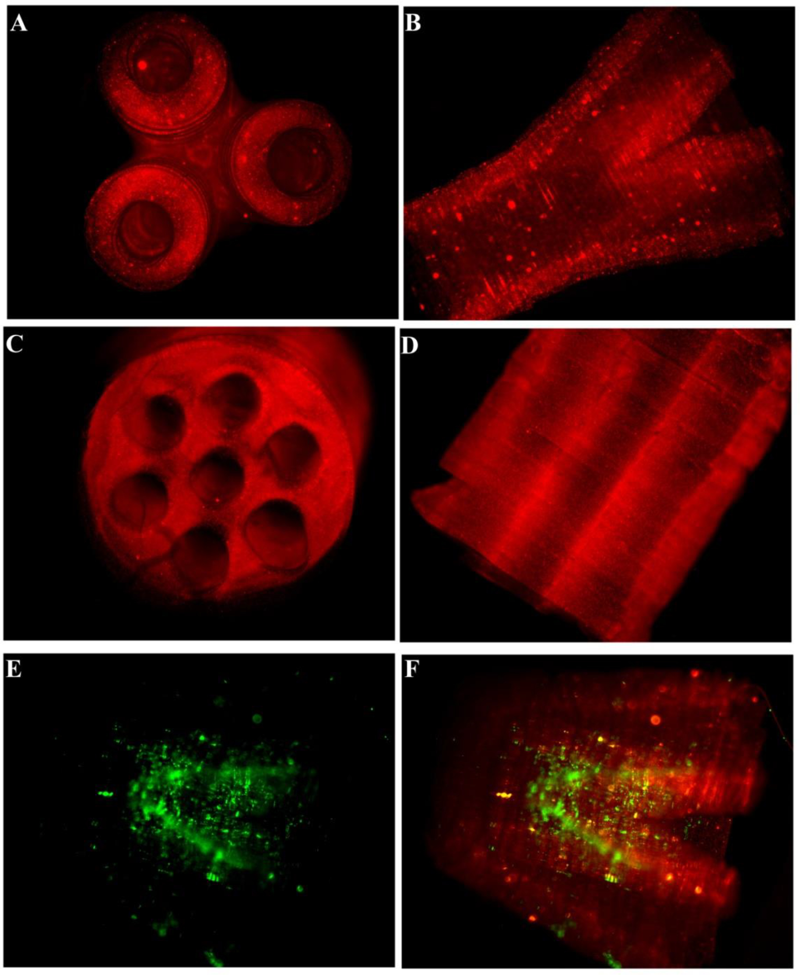
Fluorescence micrographs of the fabricated scaffolds. (A) and (B) demonstrate the lateral and top view of the branched scaffold. The scaffold starts as a single lumen conduit and divides into three branches at the other end. (C) and (D) demonstrate the lateral and top views, respectively, of the multi-lumen scaffold. (E) and (F) show the Schwann cells seeded inside the scaffold. The cells remained viable after 24 hrs when stained with calcein. Red fluorescent particles were added in the prepolymer solution to better visualize the scaffolds and the internal structure post-fabrication. (Scale bar, 1 mm)
Gradient Formation in Hydrogel Conduits
Previous studies have demonstrated that a gradient of growth factors such as NGF can guide growing neurites and help them find their target (Gundersen and Barrett, 1979; Kapur and Shoichet, 2004). Further, stimulatory and inhibitory gradients can act in conjunction to guide the cells (Goldberg and Barres, 2000). Studies have also shown that cells can sense and respond better to multiple biomolecular gradients (Chen, et al., 2010). We hypothesized that the DMD-based technology could be used to create permissive and inhibitory gradients of biomolecules (e.g., growth factors) running in opposite directions. Figure 8 illustrates opposite gradients of two different fluorescent microparticles created using the DMD microfabrication system, indicating that the system can successfully create a gradient of biomolecules. As a proof of concept, we successfully created gradients of red and green fluorescent microparticles in opposite directions. Although a thorough evaluation of growth factor distribution and cellular response is beyond the scope of this initial study, the technique clearly illustrates that multiple biomolecules can be sequestered spatially in the scaffold using the DMD microfabrication system. Ongoing in vitro and in vivo studies will further examine the proposed hypothesis.
Figure 8.
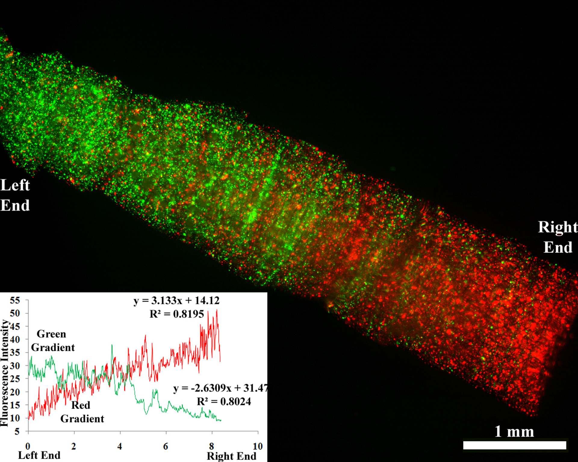
Scaffold with two gradients running in opposite directions. Red and green fluorescent microparticles were mixed in a prepolymer solution and the scaffold was fabricated. The graph indicates the intensity profile of the fluorescence and thus the microparticle concentration. (Scale bar, 1 mm)
Conclusions
In conclusion, we have developed an innovative platform for the fabrication of 3D scaffolds mimicking native nerve tissue. The DMD microfabrication system is a computer-aided, layer-by-layer manufacturing system that employs a dynamic mask for photopolymerization of an entire polymer layer simultaneously. We have developed scaffolds of intricate geometries and pore sizes using HA, a native ECM component. The fabricated scaffolds retain the biological activity of native HA as demonstrated by HAbp staining and were enzymatically degradable by hyaluronidase. We have also fabricated “designer” scaffolds with complicated microarchitecture such as cylindrical conduits with channels and branched scaffolds resembling native branched nerves. As a proof-of-concept, we developed a gradient of fluorescent microparticles in the conduit, indicating that the technique can be efficiently used to create gradients of biomolecules. Further, multiple biomolecules can be sequestered spatially as indicated by opposite gradients of red and green microparticles. Thus, the DMD microfabrication system represents a strategy to create custom-designed scaffolds with complicated microarchitecture mimicking native tissues as well as to impart biofunctionality to biomaterial-based scaffolds for regenerative medicine applications.
Acknowledgements
We gratefully acknowledge support from a NIH EB003416 to CES and SC. The authors would also like to thank the Schmidt and Chen lab members for useful discussions.
References.
- Agerup B, Berg P, and Akermark C, BioDrugs 19, 23 (2005) [DOI] [PubMed] [Google Scholar]
- Belkas JS, Shoichet MS, and Midha R, Neurol Res 26, 151 (2004) [DOI] [PubMed] [Google Scholar]
- Bellamkonda RV, Biomaterials 27, 3515 (2006) [DOI] [PubMed] [Google Scholar]
- Cen L, Neoh KG, and Kang ET, Langmuir 18, 8633 (2002) [Google Scholar]
- Chen FM, Zhang M, and Wu ZF, Biomaterials 31, 6279 (2010) [DOI] [PubMed] [Google Scholar]
- Chen WY, and Abatangelo G, Wound Repair Regen 7, 79 (1999) [DOI] [PubMed] [Google Scholar]
- Collier JH, Camp JP, Hudson TW, and Schmidt CE, J Biomed Mater Res 50, 574 (2000) [DOI] [PubMed] [Google Scholar]
- Fieber C, Plug R, Sleeman J, Dall P, Ponta H, and Hofmann M, Gene 226, 41 (1999) [DOI] [PubMed] [Google Scholar]
- Goldberg JL, and Barres BA, Annu Rev Neurosci 23, 579 (2000) [DOI] [PubMed] [Google Scholar]
- Gundersen RW, and Barrett JN, Science 206, 1079 (1979) [DOI] [PubMed] [Google Scholar]
- Han L, Mapili G, Chen SC, and Roy K, J Manufac Sci Eng 130, 021005 (2008) [Google Scholar]
- Hollister SJ, Nat Mater 4, 518 (2005) [DOI] [PubMed] [Google Scholar]
- Ikeda K, Yamauchi D, Osamura N, Hagiwara N, and Tomita K, Br J Plast Surg 56, 342 (2003) [DOI] [PubMed] [Google Scholar]
- Jiang D, Liang J, and Noble PW, Annu Rev Cell Dev Biol 23, 435 (2007) [DOI] [PubMed] [Google Scholar]
- Junarsa I, and Nealey PF, J. Vac. Sci. Technol. B 22, 2685 (2004) [Google Scholar]
- Kapur TA, and Shoichet MS, J Biomed Mater Res A 68, 235 (2004) [DOI] [PubMed] [Google Scholar]
- Kleitman N, Wood PM, and Biunge RP. Tissue culture methods for the study of myelination. (MIT press, Massachusetts. 1991).pp.337 [Google Scholar]
- Leach JB, and Schmidt CE, in Encyclopedia of Biomaterials and Biomedical Engineering, ed. By Wnek GE and Bowlin GL (Marcel Dekker; New York, 2004), p. 779. [Google Scholar]
- Lu Y, Mapili G, Suhali G, Chen SC, and Roy K, J Biomed Mater Res 77A, 396 (2006) [DOI] [PubMed] [Google Scholar]
- Mondrinos MJ, Dembzynski R, Lu L, Byrapogu VK, Wootton DM, Lelkes PI, and Zhou J, Biomaterials 27, 4399 (2006) [DOI] [PubMed] [Google Scholar]
- Ozgenel GY, Microsurgery 23, 575 (2003) [DOI] [PubMed] [Google Scholar]
- Sachlos E, and Czernuszka JT, Eur Cell Mater 5, 29 (2003) [DOI] [PubMed] [Google Scholar]
- Slevin M, Kumar S, and Gaffney J, J Biol Chem 277, 41046 (2002) [DOI] [PubMed] [Google Scholar]
- Strauch B, Hand Clin 16, 123 (2000) [PubMed] [Google Scholar]
- Suri S, and Schmidt CE, Acta Biomater 5, 2385 (2009) [DOI] [PubMed] [Google Scholar]
- Yoo HS, Lee EA, Yoon JJ, and Park TG, Biomaterials 26, 1925 (2005) [DOI] [PubMed] [Google Scholar]


