

Abstract
Objective:
To identify anatomic structures in three dimensions and examine their reliability to be used as landmarks in a three-dimensional coordinate cephalometric analysis, using cone-beam computerized tomography (CBCT).
Materials and Methods:
Thirty CBCT images were randomly selected for landmark location. Forty-two anatomic landmarks, which are not included in the traditional cephalometric landmarks, were chosen based on radiographic characteristics that make them pragmatic to mark in the CBCT image slices. The principal investigator marked the full set of landmarks on the software by navigating in the X, Y, and Z axes for every image three times, with each measurement trial being at least 1 week apart. One other investigator also located the landmarks once for each image for reliability purposes. Intraclass correlation coefficients (ICCs) were used to analyze the mean differences in landmark location in all axes.
Results:
Intra- and interexaminer reliability for x, y, and z coordinates for all landmarks had ICC greater than 0.95 with confidence interval of 0.88–0.99. Mean measurement differences found were <1.4 mm for all landmarks in all three coordinates. Mean measurement error differences obtained in the principal investigator's trials were primarily <0.5 mm.
Conclusion:
The most reliable and reproducible landmarks tested for use in CBCT are mental foramina, infraorbital foramina, inferior hamulus, dens axis, foramina transversarium of atlas, medial and lateral condyles of the mandible, superior clinoid processes, and mid-clinoid.
Keywords: Cone-beam computerized tomography, Three-dimensional cephalometrics, X-rays, Orthodontics
INTRODUCTION
For several decades, two-dimensional (2D) cephalometric radiographs have been used effectively for orthodontic diagnosis and treatment planning. Although 2D cephalometric radiography has been effective, it does present some deficiencies and limitations. The information in these radiographs is subject to projection errors as well as landmark identification problems and measurement errors because they can only produce 2D data from a three-dimensional (3D) object.1,2 In comparison, 3D volumetric imaging, such as cone-beam computerized tomography (CBCT) presents a better geometric accuracy and spatial resolution than regular computerized tomography with relatively low radiation dosages.2–5
In the past decade, the introduction of CBCT in dental radiology and its wide adoption for many clinical applications in dentistry has revived interest in using 3D cephalometric analysis for routine orthodontic cases.6 Compared with the multislice computerized tomography, CBCT is less expensive, is more accessible, and offers a lower dose of radiation.7,8 Furthermore, CBCT measurements are not significantly influenced by variation in skull orientation or head position during image acquisition.9,10 The challenge for clinicians is to understand and interpret 3D imaging.11 Currently, there are no specific guidelines about how to analyze this type of 3D image, especially in the orthodontic field. For this reason, new standards are required and clinicians need special training when dealing with 3D craniofacial images.
Linear measurements made on CBCT-derived 3D images are sufficiently clinically accurate and reliable.12 Some studies have attempted to verify whether landmarks used in conventional imaging can be extrapolated to CBCT.1,13–18 Some landmarks that are used in the 2D cephalometric analysis are challenging to locate in the CBCTs.15 Many landmarks have demonstrated low reliability in CBCT, and therefore, are not suitable for use in 3D imaging. In these studies some of the least reliable conventional landmarks in CBCT were gonion, orbitale, condylion, A point, ANS, PNS, and pogonion.15–18 Using conventional landmarks in the 3D analysis showed that 3D landmark identification using CBCT can offer consistent and reproducible data if a protocol for operator training and calibration is followed.14 Some studies19,20 have explained the need for a 3D-based measurement analysis when using a 3D Cartesian system. The reliability and repeatability of the identification landmarks are very high if the 3D cephalometric landmarks are defined correctly.21 The purpose of this study is to identify several anatomic landmarks and test their reliability in CBCT images for use in 3D cephalometric analysis.
MATERIALS AND METHODS
Institutional Ethical Review Board approval was obtained for the study. Thirty CBCT images of subjects (age range = 12–17 years) were randomly selected from the University of Alberta Orthodontic Graduate Program pool. All scans were taken for orthodontic diagnosis and treatment planning. Any CBCT scans demonstrating motion artifact were replaced. All CBCT scans were taken using the I-CAT machine (Imaging Sciences International, Hatfield, Pa) with a collimation height scan of 13 cm, scan time of 20 seconds, and resolution of 0.3 mm voxel size. Each image was converted to a Digital Imaging and Communications in Medicine (DICOM) format and analyzed using the Avizo software AVIZO 7.0, (Visualization Sciences Group, Burlington, Mass). The DICOM format images were rendered into a volumetric image.
Forty-two anatomic landmarks that are not included in the traditional cephalometric landmarks were chosen based on the radiographic characteristic of head and neck hard tissue structures, which are feasible to be localized in the CBCT images. The radiographic characteristics for choosing the landmarks were being presented as a small radiolucency, on a short curve, at the tip of a spine, and with a distinct contrast difference of the adjacent structures. The x, y, and z coordinates of each landmark were defined based on the Cartesian system used by Lagravere et al.2 (Table 1; Figures 1 through 12) to standardize the anatomic identification in the three planes of space and to guide the selection of the most precise location in the sagittal, axial, and coronal views.
Table 1.
Three-Dimensional Cephalometric Landmarks

Figure 1.

Posterior hyoid right, posterior hyoid left in the axial view and three-dimensional reconstruction.
Figure 2.
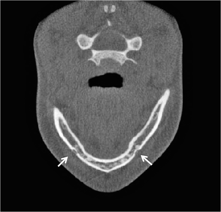
Mental foramen right, mental foramen left in the axial view.
Figure 3.
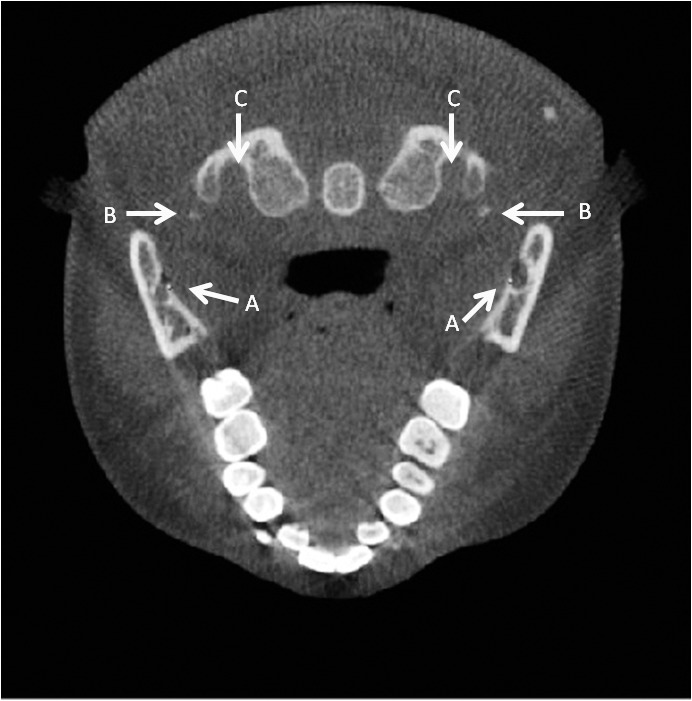
(A) Lingula right and left. (B) Right and left transversarium atlas. (C) Right and left inferior styloid process in the axial view.
Figure 4.
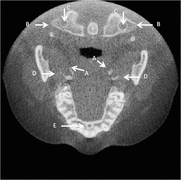
(A) Right and left inferior medial pterygoid plate. (B) Right and left transverse process atlas. (C) Right and left transversarium atlas. (D) Right and left inferior lateral pterygoid plate. (E) Oral incisive foramen in the axial view.
Figure 5.
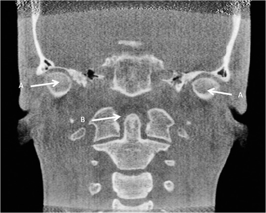
(A) Right and left medial condyle. (B) Dens axis in the coronal view.
Figure 6.
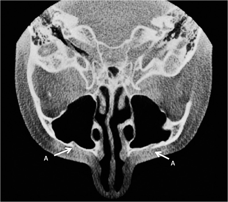
Right and left infraorbital foramina in the axial view.
Figure 7.

Posterior right and left inferior concha in the coronal view and the posterior right inferior concha in the sagittal view.
Figure 8.

(A) Anterior right condyle in the axial and sagittal views. (B) Posterior right condyle in the axial and sagittal views. (C) Superior right condyle in the sagittal view.
Figure 9.

(A) Superior right and left clinoid processes in the axial and sagittal views. (B) Mid- clinoid in the axial view.
Figure 10.
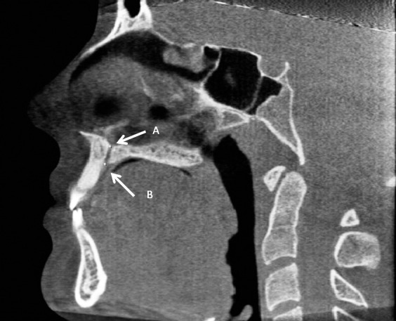
(A) Nasal incisive orifice. (B) Oral incisive foramen in the sagittal view.
Figure 11.

(A) Upper left first molar furca. (B) Lower left first molar furca in the sagittal view.
Figure 12.
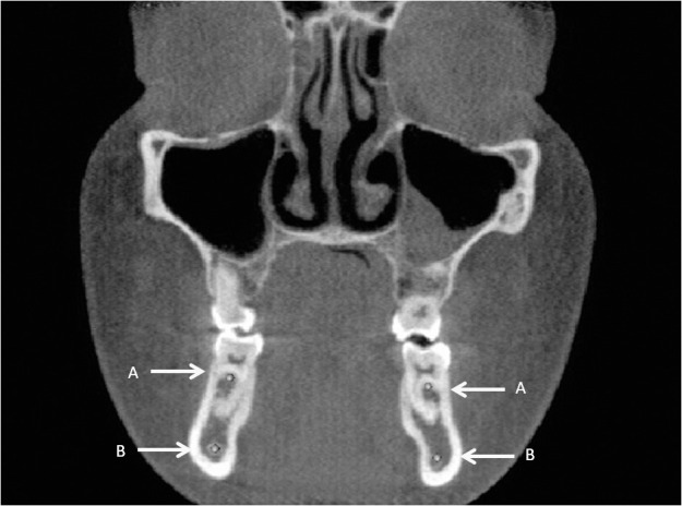
(A) Right and left upper first molar furca. (B) Right and left mandibular canal at first lower molar furca in the coronal view.
Table 1.
Continued

The principal investigator marked the landmarks in the software using the virtual spherical markers of 0.5 mm diameter in the x, y, and z axes; the center of each marker represented the exact location of the landmark. The examiners marked a landmark in the first slice in which it was visible, moving mesiodistally, superiorly-inferiorly or anteriorly-posteriorly, and then adjusting the marker in other coordinates. For example, for marking the superior left clinoid process, the left clinoid process was marked when it was visible first on the axial slice moving inferiorly; the position was then adjusted in the coronal and sagittal views if needed.
The landmarks were marked three times for every image, and each measurement trial was at least 1 week apart. One other investigator also located the landmarks once for each image for reliability purposes. To reduce exhaustion effect, both investigators would discontinue the process of landmark identification once they felt tired and then resumed the process another day.
Mean differences and descriptive statistics were calculated for all landmarks and different axes. Intraclass correlation coefficients (ICCs) were calculated to determine the intra- and interexaminer reliability of each landmark. The mean differences of all the trials of the 3D cephalometric measurements of the 42 landmarks and their standard deviations are summarized in Table 2 for all three axes. These were obtained by averaging the differences between the four total trials of landmark location of the principal investigator and the second examiner for every axis. A landmark was considered clinically reliable if it presented <1.5 mm mean difference.
Table 2.
Absolute Mean Value Measurement and Standard Deviation (mm) in Coordinates of Landmarks Based on All Trials (Intra- and Interexaminer)

RESULTS
Intraexaminer reliability for x, y, and z coordinates for all landmarks had ICC greater than 0.98 with 95% confidence interval (CI) = −0.97, 1.00. Mean measurement error differences obtained in the principal investigator's trials were primarily <0.5 mm. Interexaminer reliability for x, y, and z coordinates for all landmarks has ICC >0.95 (CI = −0.88, 0.99). Mean differences of the intraexaminer and interexaminer measurements were all <1.4 mm. The only landmarks with mean values >1 mm in any of the x, y, and z coordinates were right and left posterior-inferior concha (1.39 mm and 1.09 mm, respectively), oral incisive foramen (1.25 mm), inferior left styloid (1.07 mm), right lingula (1.03 mm), and inferior right and left lateral pterygoid (1.16 mm and 1.10 mm, respectively); the highest amount was 1.39 mm for the right posterior-inferior concha. The posterior hyoid left was not present in two CBCTs and was only marked in 28 samples.
Landmarks that had mean differences ≤0.5 mm in all coordinates were right and left mental foramina, dens axis, right and left transversarium atlas, right and left inferior hamulus, right infraorbital foramen, medial right condyle, and lateral left condyle.
DISCUSSION
Studies show that CBCT craniometric measurements are more accurate than traditional measurements and can potentially be used as a quantitative orthodontic diagnostic tool.13,22 The main advantage in tomographic scans is the possibility of interacting with previously stored data, which in turn generates new images and allows the practitioner to reconstruct synthesized cephalograms that are comparable with conventional radiographs, based on a single 3D measurement.23,24 However, the use of lateral cephalograms might be limited in some cases; for example, lateral cephalograms are difficult to accurately superimpose because of the difference between the right and left sides, such as differences in scaling ratios, variations in head positioning, and overlapping of various cranial structures 25
Some studies have analyzed the reliability of taking landmarks used in traditional cephalometry and locating them in CBCTs.1,7 Some studies have used CBCT-synthesized cephalograms and showed that the reproducibility of exams obtained from conventional cephalograms and CBCT-synthesized cephalograms was similar.24 Traditional cephalometric landmarks have been defined using a 2D x-ray, giving them just two axes to worry about.
With CBCT, visualization of structures can be done using all three axes, thus opening the possibility of analyzing new 3D-defined landmarks to use with 3D cephalometric analysis. However, the development of 3D landmark-based cephalometric analysis requires definition of 3D landmarks on complex curving structures.14 Practical considerations of identification errors, coupled with an essential need for biological relevance and a balanced representation of components of the craniofacial form, limit the number and nature of landmarks available for analysis.14 Historically, landmarks such as articulare were used because of the ease in landmark location on 2D cephalometric projections, but these projected superimposed structures do not exist in the actual 3D facial structure. For these reasons, the development of 3D landmark-based cephalometric analysis demands suitable operational definitions of the landmark location in each of the three planes of space,14,26
In this study, the goal was to analyze the ease of locating and the reliability of anatomic structures or sites to be used in the development of a 3D analysis. Clinical significance of variation in repeated landmark location is difficult to define and depends on the purpose of analysis. In traditional, clinical 2D cephalometrics, a landmark error <1 mm is considered a precise measurement. Variations <1.0 mm are unlikely to have clinical significance if the cranial base landmarks are used for linear or angular measurements.27 Variations <0.5 mm are probably not clinically significant, and variations between 0.5 mm and 1.0 mm might be clinically relevant.22 Whether this measure is applicable in 3D cephalometrics might be questionable because a third axis is introduced in 3D cephalometrics that may add errors to the overall error.7,25
All landmarks studied had mean differences <1.4 mm in all three coordinates. However, seven axis coordinates of all the landmarks identified had a value ≥1 mm. Several landmarks showed mean differences close to 0.5 mm in all three coordinates, which makes them reliable to be used in 3D analysis. During this study, the examiners faced some difficulties in locating the landmarks according to the 3D definitions, which could have affected the mean values measured. The difficulties and possible causes that make these landmarks hard to locate are listed in Table 3.
Table 3.
Challenges Presented When Trying to Identify Each Landmark

In this study, the oral incisive foramen showed 1.25 mm of mean value measurement in the z coordinate. The size of the foramen, location in the palate curvature, and anatomic variation of this structure could have caused the wide range in localizing the landmark. De Oliveira-Santos and colleagues28 demonstrated that additional palatine foramina at least 1 mm in diameter may be found in around 16% of patients of both genders and different age groups. Also, the oral incisive foramen could have been identified in different coronal planes because of its large dimension. Furthermore, it is located on the hard palate curvature, which makes it difficult to unquestionably mark its most inferior point.
The size and shape, contrast, and location of the anatomic structure can influence its accurate localizing. The precise 3D definition of the structure in three dimensions also influences localizing the landmarks.14 For example, the midpoint of upper first molar furca could be marked close to the buccal, mesial, or distal furca, within a wide area that might be more than the favorable range of 1 mm. In some of the studied CBCT slices, the posterior point of inferior concha was more like a flat plane than a pointy or curved structure, which makes it hard to define as a single point. In this study, the inferior left styloid showed a mean 1.07 mm of mean measurement value in the z coordinate. Stylohyioid ligament, which connects the styloid process to the lesser horn of the hyoid bone, can be subject to calcification.29 In a study, Alpoz and colleagues30 showed ratios of different patterns of the styloid process from the normal styloid process (68.3%), elongated styloid process (27.1%), calcified stylohyoid ligament (1.7%), and absent stylohyoid chain (2.5%). These variations might affect the examiner's judgment in the precise localizing of the landmarks.
Bone thickness, bone mineralization, and bone density can contribute to the identification of the bone bounderies.31 The quality of the scan is a crucial factor in landmark identification error. Locating the inferior alveolar nerve canal at the level of mandibular first molar furca can be influenced by the contrast and quality of the radiograph. It can be well-defined in sharp and high-quality scans and challenging to locate using scans with low signal to noise ratio. This can also be attributed to the low-density contrast with adjacent landmarks due to bone quality; however, this correlation needs to be confirmed with further study.
Locating the most inferior point of the medial pterygoid, the pterygoid hamulus was of high accuracy and reliable; however, locating the most inferior point of the lateral pterygoid process can be challenging because of the flat edge of the inferior border of the lateral pterygoid plate. Foramen transversarium of the atlas showed high reproducibility while locating. Even though it is relatively large, foramen requires searching through three or four slices. Gupta and colleagues31 reported incomplete foramen transversarium of the atlas in 8.57% of specimens. However, the center of this foramen can be estimated based on the boundaries of the transverse processes. It is suggested that the size and reliability of foramina transversarium of the axis and C3 should be studied for inclusion in cephalometric landmarks.
Overall, all landmarks showed a mean difference <1.4 mm, which makes them reliable for use in 3D cephalometric analysis; however, some specific landmarks showed a much lower mean difference in locating and can be used for 3D cephalometric analysis. Future studies are recommended to assess the deviation of the marked landmarks from the skull model using radiopaque markers and to evaluate changes in these landmarks as subjects age.
CONCLUSION
The most reliable and reproducible landmarks tested for use in CBCT are mental foramina, infraorbital foramina, inferior hamulus, dens axis, foramina transversarium of atlas, medial and lateral condyles of the mandible, superior clinoid processes, and mid-clinoid.
REFERENCES
- 1.Lagravere MO, Gordon JM, Guedes IH, et al. Reliability of traditional cephalometric landmarks as seen in three-dimensional analysis in maxillary expansion treatments. Angle Orthod. 2009;79:1047–1056. doi: 10.2319/010509-10R.1. [DOI] [PubMed] [Google Scholar]
- 2.Lagravere MO, Low C, Flores-Mir C, et al. Intraexaminer and interexaminer reliabilities of landmark identification on digitized lateral cephalograms and formatted 3-dimensional cone-beam computerized tomography images. Am J Orthod Dentofacial Orthop. 2010;137:598–604. doi: 10.1016/j.ajodo.2008.07.018. [DOI] [PubMed] [Google Scholar]
- 3.Boeddinghaus R, Whyte A. Current concepts in maxillofacial imaging. Eur J Radiol. 2008;66:396–3418. doi: 10.1016/j.ejrad.2007.11.019. [DOI] [PubMed] [Google Scholar]
- 4.Pinsky HM, Dyda S, Pinsky RW, Misch KA, Sarment DP. Accuracy of three-dimensional measurements using cone-beam CT. Dentomaxillofac Radiol. 2006;35:410–416. doi: 10.1259/dmfr/20987648. [DOI] [PubMed] [Google Scholar]
- 5.Cevidanes LH, Bailey LJ, Tucker SF, et al. Three-dimensional cone-beam computed tomography for assessment of mandibular changes after orthognathic surgery. Am J Orthod Dentofacial Orthop. 2007;131:44–50. doi: 10.1016/j.ajodo.2005.03.029. [DOI] [PMC free article] [PubMed] [Google Scholar]
- 6.Maeda M, Katsumata A, Ariji Y, et al. 3D-CT evaluation of facial asymmetry in patients with maxillofacial deformities. Oral Surg Oral Med Oral Pathol Oral Radiol Endod. 2006;102:382–390. doi: 10.1016/j.tripleo.2005.10.057. [DOI] [PubMed] [Google Scholar]
- 7.Hassan B, Nijkamp P, Verheij H, et al. Precision of identifying cephalometric landmarks with cone beam computed tomography in vivo. Eur J Orthod. 2013;35:38–44. doi: 10.1093/ejo/cjr050. [DOI] [PubMed] [Google Scholar]
- 8.Suomalainen A, Kiljunen T, Käser Y, Peltola J, Kortesniemi M. Dosimetry and image quality of four dental cone beam computed tomography scanners compared with multislice computed tomography scanners. Dentomaxillofac Radiol. 2009;38:367–378. doi: 10.1259/dmfr/15779208. [DOI] [PubMed] [Google Scholar]
- 9.Ludlow JB, Laster WS, See M, Bailey LJ, Hershey HG. Accuracy of measurements of mandibular anatomy in cone beam computed tomography images. Oral Surg Oral Med Oral Pathol Oral Radiol Endod. 2007;103:534–542. doi: 10.1016/j.tripleo.2006.04.008. [DOI] [PMC free article] [PubMed] [Google Scholar]
- 10.Frongia G, Piancino MG, Bracco P. Cone-beam computed tomography: accuracy of three-dimensional cephalometry analysis and influence of patient scanning position. J Craniofac Surg. 2012;23:1038–1043. doi: 10.1097/SCS.0b013e318252d5e1. [DOI] [PubMed] [Google Scholar]
- 11.Mah J, Hatcher D. Current status and future needs in craniofacial imaging. Orthod Craniofac Res. 2003;(suppl 1):10–16; discussion 179–182. doi: 10.1034/j.1600-0544.2003.230.x. [DOI] [PubMed] [Google Scholar]
- 12.Periago DR, Scarfe WC, Moshiri M, Scheetz JP, Silveira AM, Farman AG. Linear accuracy and reliability of cone beam CT derived 3-dimensional images constructed using an orthodontic volumetric rendering program. Angle Orthod. 2008;78:387–395. doi: 10.2319/122106-52.1. 10.2319/122106-52.1. [DOI] [PubMed] [Google Scholar]
- 13.Gribel BF, Gribel MN, Frazao DC, McNamara JA, Jr, Manzi FR. Accuracy and reliability of craniometric measurements on lateral cephalometry and 3D measurements on CBCT scans. Angle Orthod. 2011;81:26–35. doi: 10.2319/032210-166.1. [DOI] [PMC free article] [PubMed] [Google Scholar]
- 14.De Oliveira AE, Cevidanes LH, Phillips C, Motta A, Burke B, Tyndall D. Observer reliability of three-dimensional cephalometric landmark identification on cone-beam computerized tomography. Oral Surg Oral Med Oral Pathol Oral Radiol Endod. 2009;107:256–265. doi: 10.1016/j.tripleo.2008.05.039. [DOI] [PMC free article] [PubMed] [Google Scholar]
- 15.Katkar RA, Kummet C, Dawson D, et al. Comparison of observer reliability of three-dimensional cephalometric landmark identification on subject images from Galileos and i-CAT cone beam CT. Dentomaxillofac Radiol. 2013;42:20130059. doi: 10.1259/dmfr.20130059. [DOI] [PMC free article] [PubMed] [Google Scholar]
- 16.De Oliveira AE, Cevidanes LH, Phillips C, Motta A, Burke B, Tyndall D. Observer reliability of three-dimensional cephalometric landmark identification on cone-beam computerized tomography. Oral Sur Oral Med Oral Pathol Oral Radiol Endod. 2009;107:256–265. doi: 10.1016/j.tripleo.2008.05.039. [DOI] [PMC free article] [PubMed] [Google Scholar]
- 17.Chien PC, Parks ET, Eraso F, Hartsfield JK, Roberts WE, Ofner S. Comparison of reliability in anatomical landmark identification using two-dimensional digital cephalometrics andthree-dimensional cone beam computed tomography in vivo. Dentomaxillofac Radiol. 2009;38:262–273. doi: 10.1259/dmfr/81889955. [DOI] [PubMed] [Google Scholar]
- 18.Ludlow JB, Gubler M, Cevidanes L, Mol A. Precision of cephalometric landmark identification: cone-beam computed tomography vs conventional cephalometric views. Am J Orthod Dentofacial Orthop. 2009;136:312.e1–3.12.e10; discussion 312–313. doi: 10.1016/j.ajodo.2008.12.018. 10.1016/j.ajodo.2008.12.018. [DOI] [PMC free article] [PubMed] [Google Scholar]
- 19.Swennen GR, Schutyser F, Barth EL, De Groeve P, De Mey A. A new method of 3-D cephalometry Part I: the anatomic Cartesian 3-D reference system. J Craniofac Surg. 2006;17:314–325. doi: 10.1097/00001665-200603000-00019. [DOI] [PubMed] [Google Scholar]
- 20.Tausche E, Hansen L, Hietschold V, Lagravere MO, Harzer W. Three-dimensional evaluation of surgically assisted implant bone-borne rapid maxillary expansion: a pilot study. Am J Orthod Dentofacial Orthop. 2007;131(suppl):S92–S99. doi: 10.1016/j.ajodo.2006.07.021. [DOI] [PubMed] [Google Scholar]
- 21.Frongia G, Piancino MG, Bracco AA, Crincoli V, Debernardi CL, Bracco P. Assessment of the reliability and repeatability of landmarks using 3-D cephalometric software. Cranio. 2012;30:255–263. doi: 10.1179/crn.2012.039. [DOI] [PubMed] [Google Scholar]
- 22.Mah JK, Huang JC, Choo H. Practical applications of cone-beam computed tomography in orthodontics. J Am Dent Assoc. 2010;(suppl 3):7S–13S. doi: 10.14219/jada.archive.2010.0361. [DOI] [PubMed] [Google Scholar]
- 23.Farman AG, Scarfe WC. Development of imaging selection criteria and procedures should precede cephalometric assessment with cone-beam computed tomography. Am J Orthod Dentofacial Orthop. 2006;130:257–265. doi: 10.1016/j.ajodo.2005.10.021. [DOI] [PubMed] [Google Scholar]
- 24.Liedke GS, Delamare EL, Vizzotto MB, et al. Comparative study between conventional and cone beam CT-synthesized half and total skull cephalograms. Dentomaxillofac Radiol. 2012;41:136–142. doi: 10.1259/dmfr/22287302. [DOI] [PMC free article] [PubMed] [Google Scholar]
- 25.Park SH, Yu HS, Kim KD, Lee KJ, Baik HS. A proposal for a new analysis of craniofacial morphology by 3-dimensional computed tomography. Am J Orthod Dentofacial Orthop. 2006;129:600.e23–e34. doi: 10.1016/j.ajodo.2005.11.032. [DOI] [PubMed] [Google Scholar]
- 26.Cevidanes LH, Styner MA, Proffit WR. Image analysis and superimposition of 3-dimensional cone-beam computed tomography models. Am J Orthod Dentofacial Orthop. 2006;129:611–618. doi: 10.1016/j.ajodo.2005.12.008. [DOI] [PMC free article] [PubMed] [Google Scholar]
- 27.Lagravère MO, Gordon JM, Flores-Mir C, Carey J, Heo G, Major PW. Cranial base foramen location accuracy and reliability in cone-beam computerized tomography. Am J Orthod Dentofacial Orthop. 2011;139:e203–e210. doi: 10.1016/j.ajodo.2009.06.027. [DOI] [PubMed] [Google Scholar]
- 28.De Oliveira-Santos C, Rubira-Bullen IR, Monteiro SA, León JE, Jacobs R. Neurovascular anatomical variations in the anterior palate observed on CBCT images. Clin Oral Implants Res. 2013;24:1044–1048. doi: 10.1111/j.1600-0501.2012.02497.x. [DOI] [PubMed] [Google Scholar]
- 29.Kosar MI, Atalar MH, Sabanciogullari V, et al. Evaluation of the length and angulation of the styloid process in the patient with pre-diagnosis of Eagle syndrome. Folia Morphol. 2011;70(4):295–299. [PubMed] [Google Scholar]
- 30.Alpoz E, Akar GC, Celik S, Govsa F, Lomcali G. Prevalence and pattern of stylohyoid chain complex patterns detected by panoramic radiographs among Turkish population. Surg Radiol Anat. 2013 doi: 10.1007/s00276-013-1137-x. epub ahead of print. [DOI] [PubMed] [Google Scholar]
- 31.Gupta C, Radhakrishnan P, Palimar V, D'souza AS, Kiruba NL. A quantitative analysis of atlas vertebrae and its abnormalities. J Morphol Sci. 2013;30:77–81. [Google Scholar]