

Abstract
Surgical reduction of pelvic dislocation is a challenging procedure with poor long-term prognosis if reduction does not accurately restore natural morphology. The procedure often requires long fluoroscopic exposure times and trial-and-error to achieve accurate reduction. We report a method to automatically compute the target pose of dislocated bones in preoperative CT and provide 3D guidance of reduction using routine 2D fluoroscopy. A pelvic statistical shape model (SSM) and a statistical pose model (SPM) were formed from an atlas of 40 pelvic CT images. Multi-body bone segmentation was achieved by mapping the SSM to a preoperative CT via an active shape model. The target reduction pose for the dislocated bone is estimated by fitting the poses of undislocated bones to the SPM. Intraoperatively, multiple bones are registered to fluoroscopy images via 3D–2D registration to obtain 3D pose estimates from 2D images. The method was examined in three studies: (1) a simulation study of 40 CT images simulating a range of dislocation patterns; (2) a pelvic phantom study with controlled dislocation of the left innominate bone; (3) a clinical case study investigating feasibility in images acquired during pelvic reduction surgery. Experiments investigated the accuracy of registration as a function of initialization error (capture range), image quality (radiation dose and image noise), and field of view (FOV) size. The simulation study achieved target pose estimation with translational error of median 2.3 mm (1.4 mm interquartile range, IQR) and rotational error of 2.1° (1.3° IQR). 3D–2D registration yielded 0.3 mm (0.2 mm IQR) in-plane and 0.3 mm (0.2 mm IQR) out-of-plane translational error, with in-plane capture range of ±50 mm and out-of-plane capture range of ±120 mm. The phantom study demonstrated 3D–2D target registration error of 2.5 mm (1.5 mm IQR), and the method was robust over a large dose range, down to 5 μGy/frame (an order of magnitude lower than the nominal fluoroscopic dose). The clinical feasibility study demonstrated accurate registration with both preoperative and intraoperative radiographs, yielding 3.1 mm (1.0 mm IQR) projection distance error with robust performance for FOV ranging from 340 × 340 mm2 to 170 × 170 mm2 (at the image plane). The method demonstrated accurate estimation of the target reduction pose in simulation, phantom, and a clinical feasibility study for a broad range of dislocation patterns, initialization error, dose levels, and FOV size. The system provides a novel means of guidance and assessment of pelvic reduction from routinely acquired preoperative CT and intraoperative fluoroscopy. The method has the potential to reduce radiation dose by minimizing trial-and-error and to improve outcomes by guiding more accurate reduction of joint dislocations.
Keywords: image-guided surgery, image registration, 3D–2D registration, orthopaedic trauma, pelvic trauma, statistical shape model, fluoroscopy guidance
1. Introduction
Pelvic dislocation is a severe pelvic injury that involves dislocations of the sacroiliac (SI) joint with frequent concurrence of pubic symphysis (PS) disruption (Halawi 2016) without bone fractures. Pelvis dislocation without bone fractures consists of 5% to 27% of pelvic trauma, depending on different studies (Dunn and Morris 1968, Holdsworth 2012). Following diagnosis and planning in CT (often in the emergency setting), surgical treatment of pelvic dislocation typically involves open or closed reduction and internal fixation under guidance of intraoperative x-ray fluoroscopy. Accurate reduction is challenged by the difficulty in reckoning the pose of complex 3D pelvic anatomy from 2D fluoroscopic projections, resulting in extended fluoroscopy time and frequent trial-and-error even for experienced trauma surgeons. In addition, residual displacement after reduction surgery (>4 mm) is associated with long-term complications such as persistent pain, limb length discrepancy, and disability (Smith et al 2005, Shillito et al 2014).
The surgical plan (i.e. determination of the dislocated bone(s) and definition of the target orientation) is performed based on preoperative CT—either qualitatively or with the assistance of various 2D or 3D manual planning tools. For example, segmentation of preoperative CT and virtual 3D image manipulation has been proposed as a basis for planning (Cimerman and Kristan 2007, Suero et al 2010, Pahuta et al 2012); however, manual manipulation is time consuming relative to rapid trauma workflow—for example, Suero et al (2010) reporting 174.8 min average planning time for a fracture of the tibial plateau.
Emerging methods for automatic image segmentation and registration provide the potential for more streamlined, accurate, and quantitative preoperative planning. Atlas-based techniques have been widely reported as a means to relate population-based prior information to patient-specific images. Statistical shape models (SSMs) are a commonly used atlas-based approach to model anatomical shape variations of a single object in a linear space via principal component analysis (PCA) and have been incorporated in active shape model (ASM) segmentation (Cootes et al 1995) and surgical trajectory planning for pelvic fracture fixation (Goerres et al 2017, Han et al 2019). An ASM segmentation with constraints on proximity of multiple bone components was proposed in Brehler et al (2019) for analysis of ankle morphology. To study the shape and pose of multiple objects, Fletcher et al (2004) used a Lie group framework to define principal geodesic analysis (PGA) for statistical analysis and segmentation of shapes modeled by a set of connected continuous medial manifolds in a nonlinear Lie group space. Bossa and Olmos (2006) proposed a statistical pose model (SPM) representation on the PGA Lie group framework for shape analysis in brain images. Related methods were further extended by Gorczowski et al (2010) to a multi-object scenario to study the shapes and poses of multiple brain structures simultaneously.
Advances in image-guided surgery, such as 3D intraoperative imaging (Tormenti et al 2010, Waschke et al 2013) and surgical tracking (Mezger et al 2013), offer opportunities to improve the precision and safety of orthopaedic surgery. Intraoperative CT or cone-beam CT (CBCT) provides visualization of bone morphology in relation to adjacent nerves and vessels; however, while such imaging systems are fairly widespread in cranial and spinal surgery, they are not broadly prevalent in orthopaedic trauma, where 2D fluoroscopic guidance is a mainstay. Tracking and navigation approaches usually involve fiducial markers placed on the patient and interventional devices, allowing registration of preoperative imaging to the world coordinate frame during surgery; again, while fairly common in neurosurgery, the use of navigation in orthopaedic trauma surgery is rare, due in part to the additional workflow associated with such systems.
To overcome such limitations in workflow (as well as cost and equipment), methods for 3D–2D registration-based guidance are being developed to register routinely acquired x-ray fluoroscopy images to preoperative 3D imaging as a basis for surgical guidance. For example, (Otake et al 2013, Uneri et al 2014a, 2014b, De Silva et al 2016) demonstrated the use of image registration between preoperative CT and 2D fluoroscopy for target localization and guidance in spine surgery. Furthermore, Han et al (2019) showed 3D–2D registration as a basis for augmenting fluoroscopy with automatically determined 3D planning information in pelvic trauma surgery. However, these registration methods do not account for independent motions of multiple bones during the operation, presenting a source of geometric error that challenges conventional rigid registration methods. To address such limitations, Koyanagi et al (2011), Schmid and Chênes (2015) proposed piecewise rigid 3D–2D registration in which multi-body 3D points are registered to fluoroscopy via feature point matching. Alternatively, Ketcha et al (2017) used a multi-scale 3D–2D image registration approach to account for deformation in spine surgery.
In the work reported below, we incorporate the SSM pelvic segmentation of Han et al (2019) and the SPM analysis of Bossa and Olmos (2006) to obtain a framework for computing the target pose of multiple bone components in surgical reduction. The resulting method provides a means to guide reduction of a dislocated bone (or bones) to the target pose using routinely acquired intraoperative fluoroscopy/radiography without the need for manual segmentation or feature point identification. The approach can be used to augment fluoroscopic images with a 2D overlay of the 3D target reduction; alternatively, the method can be used as a basis for 3D tracking of the relative locations of multiple bone components with respect to the preoperative plan and to guide residual reduction needed to match the target pose. The method estimates 3D pose from just one or two fluoroscopic images, helping to reduce the challenge of interpreting complex 3D morphology in 2D projections and potentially decreasing trial-and-error and radiation dose. By facilitating guidance relative to 2D fluoroscopy and/or 3D preoperative CT, the method could improve the accuracy of pelvic reduction and associated clinical outcomes without additional devices or major changes to surgical workflow.
2. Methods
The proposed approach for image-guided reduction of pelvic dislocation is illustrated in figure 1, using multi-body registration to: (1) preoperatively compute the target pose among multiple bone components; and (2) intraoperatively guide the reduction of dislocated bone by fluoroscopy-based navigation. The top branch in figure 1 illustrates the SSMs of three pelvic bones (sacrum and left/right innominate bones) preoperatively registered via ASM to the patient CT to obtain multi-body segmentations and target poses. An SPM is then fitted to one or more bones that are not dislocated for estimation of the target pose of the dislocated bone. The target pose constitutes the preoperative plan for reduction of the dislocation. The bottom branch of figure 1 shows automatically computed segmentations of multiple rigid bodies (three bones of the pelvis) intraoperatively mapped to one or more 2D radiographs via a two-stage 3D–2D registration: first, matching digitally reconstructed radiographs (DRRs) to the 2D radiographs to resolve the pose of one bone with respect to the x-ray system; and second, to compute the pose of the pelvic bones with respect to each other. The target reduction pose is then overlaid on the fluoroscopy image to provide guidance in a form that is familiar to orthopaedic surgeons (i.e. the 2D fluoroscopic scene). Because the resulting registrations provide 3D pose estimations, they can alternatively be used to provide 3D visualization and guidance analogous to conventional surgical navigation—i.e. visualization relative to preoperative CT. In either 2D or 3D guidance, the target pose estimation augments the surgeon’s determination of the extent to which the current reduction is within an acceptable range of the desired reduction.
Figure 1.

Flowchart for automatic multi-body planning and fluoroscopy guidance in reduction of pelvic dislocation. Preoperative registration steps are in the top branch (gray), and intraoperative steps are in the bottom branch (blue). The intraoperative steps involve a two-stage registration, with the first stage (solid dark blue) solving for one bone component to the x-ray system geometry and the second stage (dashed light blue) solving for inter-body poses.
2.1. Preoperative reduction planning
2.1.1. Pelvic shape atlas and segmentation
An open-source pelvic atlas (Han et al 2019) comprised of N = 40 CT images drawn from the Cancer Imaging Archive (Roth et al 2014, Seff et al 2014) was used, with separate segmentations of left/right innominate bone (i.e. ilium, ischium, and pubis) and sacrum represented by triangular surface meshes with corresponding vertices across the atlas population. The individual bone SSMs were represented as , where is the population mean shape, PSSM is the principal component matrix, vSSM is a weight vector describing the populational shape variation, and the superscript l = 1 … L denotes the L = 3 pelvic bones. The pelvic bones were segmented using a multi-resolution ASM (Cootes et al 1995) to optimize image gradient magnitude along SSM boundaries via updates to the SSM weight vector and overall pose similarity transformation . An unconstrained free-form deformation step (Han et al 2019) further refined the ASM output to produce the final segmentation surfaces denoted as triangular meshes S(l), l = 1, 2, 3. Details of the implementation can be found in Han et al (2019). These segmentations provided a basis for the pose estimation method described below.
2.1.2. SPM and definition of target pose
The pelvic bones were treated as a multi-object model for which the relative poses (or the respective similarity transformations between bones) could be jointly modeled. Analogous to SSM in which PCA is used for multivariate shape analysis on a Euclidean space, the multivariate pose analysis was computed using PGA on a Riemannian manifold (Fletcher et al 2004, Bossa and Olmos 2006). A Riemannian manifold is a smooth manifold equipped with an inner product (generalized Euclidean space) on the tangent space of its points. The similarity transformation is written in homogenous coordinates as:
| (1) |
where is a scaling parameter, R3×3 ∈ SO(3) is an orthogonal rotational matrix, and is a 3D translation vector. The group of matrices following equation (1) forms a Lie group, which is globally curved but locally linear (i.e. Euclidean in the tangent space). The Lie group and its tangent space can be inter-converted using exponential and logarithm mapping due to the following properties:
| (2a) |
| (2b) |
| (2c) |
where (tx, ty, tz) are translation parameters, (rx, ry, rz) ∈ SO(3) are rotational parameters belonging to the 3D rotation group and I3 is an identity matrix of dimension 3 × 3. The tangent space of the similarity transformation can then be defined by a set of 7 parameters:
| (3) |
The b vector is an equivalent Euclidean space representation of the similarity transformation. Hence, any similarity transformation can be written as an exponential mapping of its orthogonal basis decomposition:
| (4a) |
| (4b) |
where [b]i denotes the ith component of b, and [B]i,j denotes the ith column and jth row of B. The orthogonal basis B shares the same form as the matrices in the exponential operation in equation (2). Given two similarity transformations T1 and T2, the distance D between the two along the manifold is denoted as the geodesic distance and can be computed in the tangent space via logarithmic mapping:
| (5) |
where ln() is the inverse function of equation (4a) that converts a transformation to a Lie group b vector. Equation (5) defines a distance metric of the similarity transformation that forms the basis of mean and variance computation required for PGA, which is equivalent to performing PCA on the b vectors and converting to the Lie group space via exponential mapping. The result of the PGA is referred to as the SPM.
To create a SPM given a dataset of N atlas members, each with L objects, the dataset is first normalized by globally aligning the members to a common reference frame using the Procrustes method. The pose of each object instance , n ∈ [1, N], l ∈ [1, L] with respect to the mean pose—i.e. the local pose difference—is then:
| (6) |
where is the squared Procrustes metric after similarity alignment, and is the mean shape of object l. By converting the poses into the Euclidean space parameters , concatenating the L poses into a column vector , and concatenating N pose vectors into a matrix , the PGA results in:
| (7) |
where is the mean pose vector, is the principal component matrix and is a weight vector describing the populational pose variation. Figure 2 shows the first four modes of pose variation in the pelvis SPM, with the ±3λ standard deviation of the pose model shown in yellow and green, respectively. The first mode represents the superior-inferior shift of the sacrum with respect to the innominate bones; the second mode represents rotational pose change in the axial plane, similar to the open-book flexion of the pelvis; the third mode represents rotational pose change in the sagittal plane (with the sacrum showing more rotational variation than the innominate bones); and the fourth mode represents the rotational change of the innominate bones in the coronal plane with respect to the sacrum.
Figure 2.

SPM of the pelvis. (a)–(d) The first four modes of variation (+3λ in yellow, −3λ in green) in pose of the sacrum and innominate bones.
In estimation of the target reduction—for example, the desired pose of the left innominate bone following dislocation—the poses bO of observed undislocated bones SO (the sacrum and right innominate defined by ASM segmentation) can be fitted to the SPM to infer the unknown pose bX of the dislocated bone SX before dislocation (left innominate) using incomplete PCA (Vidal et al 2016):
| (8a) |
| (8b) |
where O and X are the indices of the undislocated and dislocated bones, respectively. The estimated SPM weight vector in equation (8a) was solved using trust region gradient-based optimization (Steihaug 1983), and the target pose after reduction of the dislocated bone was computed through exponential mapping as in equation (4a).
The SPM solution does not account for local shape variations of the pelvis and could result in overlap at the SI and PS joint spaces. A refinement step was therefore incorporated by imposing a collision constraint on opposing joint surfaces obtained from annotations in the SSM: the surface normals over the joint surfaces were computed, and a ray-tracing collision detection (Hermann et al 2008) was performed between opposing surfaces. Transformations resulting in overlap between opposing surfaces were refined locally by the smallest 3D translation Drefine to the dislocated bone along the direction of the surface normal. The final target pose of the dislocated bone with respect to the mean pose was the composition of the pose from the SPM and the collision constraint refinement: Ttarget = DrefineTX. The method without the collision refinement is termed SPM, and the method with the collision constraint is termed SPMCC.
2.2. Multi-body 3D–2D registration
2.2.1. First-stage registration: resolving one bone component to the system geometry
In the first stage of the registration process, the pose of one bone component is resolved with respect to the x-ray imaging system geometry. For registration to multiple fluoroscopic images, the system geometry associated with each image can be obtained via separate registration to each image. The system geometry is parametrized by the projection matrix H, which characterizes the projective transform and can be decomposed into 9 degrees of freedom (DoF) describing the intrinsics (source position Ts = [Ts,x, Ts,y, Ts,z]T and extrinsics (detector position Td = [Td,x, Td,y, Td,z]T and 3D rotation of the detector Rd =[Rd,x, Rd,y, Rd,z]T). The projection matrix can be expressed as:
| (9) |
such that any voxel in the 3D domain can be forward projected to the detector plane by multiplying its homogenous coordinates by . For a calibrated x-ray system such as a C-arm for which the projection matrix H is known, the pose of one bone with respect to the system can be simplified to a 6 DoF transformation, T, containing only the extrinsics (the second term in equation (9)).
Following the notion of ‘self-calibration’ described in Ouadah et al (2016), Uneri et al (2017), the first stage registers a single bone with salient image features (e.g. the left or right innominate bone) to a single 2D projection. For forward projection of the DRR, the single bone ASM segmentation surface was voxelized to a binary volume and each nonzero voxel is filled with its corresponding attenuation coefficients from the preoperative CT. DRRs were computed via linear forward projection of the bone volume. Gradient orientation (GO) was used as the similarity metric between the DRR and projection image, which was previously shown to be robust in a variety of clinical scenarios, including cases of content mismatch (e.g. surgical instruments in the projection image but absent from the 3D model (De Silva et al 2016)):
| (10) |
where ∇ denotes the gradient operator, ψi denotes the angle between gradient vectors ∇I1 (i) and ∇I2 (i) at pixel location i, and N and NLB denote the number of evaluated pixels and the lower bound (half of the total pixels in the radiograph), respectively. Only pixels with gradient magnitude exceeding the threshold values t1 and t2 (set as the median gradient magnitude of I1 and I2) are evaluated. The first stage registration solves for either H (for a 9 DoF system, such as a mobile radiography system, equation 11(a)) or T (for a 6 DoF system such as a calibrated mobile C-arm, equation 11(b)) by maximizing GO:
| (11a) |
| (11b) |
where is the ray from the x-ray source position along the projection matrix direction, and the integral represents the DRR computed by linear forward projection of the bone component.
2.2.2. Second-stage registration: solving inter-body poses
A second stage registration resolves the L inter-body poses parametrized by 6 × (L − 1) DoF rigid transformations. Similar to section 2.2.1, multi-body 3D models S(l) were voxelized from ASM segmentations with attenuation coefficients from CT. DRRs were computed as the summation of the linear forward projection of the multi-body 3D models via the resolved system projection matrix Ĥ, and the image similarity metric GO was measured between the DRRs and the radiographs R. The multi-body 3D–2D registration solves for the set of rigid 6 DoF transformations of the 3D models that maximizes the summation of GO from K radiographs:
| (12) |
where K is the total number of fluoroscopic images used for registration and can be as few as 1. Rk is the kth fluoroscopic image, and Ĥk is the associated system projection matrix.
Equation (12) was solved using covariance matrix adaption evolution strategy (CMA-ES) optimization, with the same multi-resolution pyramid as in the first-stage registration. The 3D–2D registration serves as an image-based tracking method of the dislocated bone(s) T3D2D,X with respect to the observed undislocated bone(s) T3D2D,O. The target reduction pose computed in section 2.1.2 can thus be transformed into the intraoperative coordinate frame as T3D2D,O Ttarget and forward projected onto the radiograph for 2D augmented guidance , as illustrated in figure 3(b). In addition, the residual transformation required to reduce the dislocated bone from the current location to the target can be computed as . As shown in figure 3(c), such information can be used for 3D visualization of the current reduction with respect to the preoperative target reduction. The proposed multibody 3D–2D registration therefore can provide both 2D fluoroscopy augmentation and 3D navigation using intraoperative 2D images alone.
Figure 3.

Multi-body 3D–2D registration and guidance. (a) AP fluoroscopic image of a pelvis with left innominate dislocation. The DRR Canny edges (yellow) computed from the left/right innominate bones and sacrum after registration overlaid on the fluoroscopic image show close alignment. (b) The fluoroscopic image is augmented with a projection (green) of the target pose of the dislocated innominate bone using the resulting 3D–2D registration to visualize the current state of the patient relative to the target pose (and possible need for further reduction). (c) 3D rendering of preoperative CT overlaid with the target pose (green) of the dislocated left innominate bone.
Equations (11) and (12) were solved using the CMA-ES optimization algorithm (Hansen et al 2003) using a two-stage multi-resolution pyramid with image downsampling factor of [4×, 2×], a population size of [100, 100], and initial standard deviation σ of [4, 1] mm and [4, 1]°. The robustness of CMA-ES generally improves by increasing the population size to more densely sample the search space at the cost of performing more function evaluations (Otake et al 2013). A population size of 100 was empirically determined to yield robust 3D–2D registration without severe compromise in computation time. An excessively large value of σ results in large search space that decreases robustness and requires an increased sampling population, whereas setting σ to a value that is too small inhibits convergence. The initial setting of σ = 4 {mm, °} at the coarser resolution (4× downsampling) represents an initial search range of ~±8 {mm, °} according to Gaussian distribution and was found to be sufficient for this work. The value of σ is reduced to finer scale σ = 1 {mm, °} at the latter stage (2× downsampling) to achieve local refinement.
2.3. Experiments
2.3.1. Experimental comparison: alternative pose estimation methods
Two other pose estimation methods were implemented and experimentally tested as a basis of comparison to the SPM approach: (1) treating the pelvic SSM as a single, rigid object (cf, L separate rigid components); and (2) based on the assumption of pelvic symmetry about the sagittal plane. Both alternative methods used triangular mesh surfaces from ASM segmentation. In the first, an SSM of the pelvis was constructed as a single object as in section 2.1.1, such that . The full pelvis SSM couples the shape and pose variations and hence can be used to estimate shape and pose simultaneously. After ASM segmentation of the observed undislocated bones SO, the vertices of the target bone surface SX can be estimated in a manner similar to equation (8):
| (13a) |
| (13b) |
The target pose of the dislocated bone can be computed by Procrustes rigid alignment of the mean shape to the target shape . The method is referred to as ‘single-pelvis SSM,’ or SSMsingle for short.
In the second method, the target pose of the dislocated innominate bone was estimated as the mirrored pose of the undislocated contralateral side reflected about the plane of symmetry defined by the sacral midline. The transformation was solved using the rigid-body method of (Combes et al 2008) using the vertices point cloud of the ASM sacrum segmentation. The method is referred to as ‘contralateral mirroring,’ or CM in short.
2.3.2. Simulation study
Preoperative estimation of the target reduction (section 2.1) and intraoperative multi-body 3D–2D registration (section 2.2) were evaluated in a simulation study involving a leave-one-out cross-validation of the atlas (N = 40). For each atlas member, the corresponding CT image and pelvic bone segmentations were used to simulate pelvic dislocations. A range of dislocations Tdisl were simulated, including PS dislocation, SI joint dislocation, and combinations of the two following dislocation patterns from case studies reported in Mulhall et al (2002), Çıçek et al (2015), with dislocation magnitude uniformly distributed from 0 to 20 mm and 0°–10°. Pure PS dislocation corresponds to a small and clinically insignificant disruption of the SI joint, which is not treated surgically and was not addressed in this paper. The upper limit of the simulated dislocation was based on maximum clinical measurements (Zhang et al 2009, Kim et al 2016). Dislocations that resulted in collision between bones were removed, and new simulations were generated. Gap regions left by bone dislocation were infilled by linear interpolation of adjacent soft-tissue regions. The remaining 39 members were used to construct the SSM and SPM for segmentation and estimation of the target reduction.
The ASM segmentation accuracy was quantified in terms of the Dice Coefficient and the surface segmentation root mean square deviation (RMSD) between vertices from the segmentation and ground truth (defined by manual segmentation in the pelvis atlas with intra-observer variability of 0.93 ± 0.01 Dice Coefficient (Han et al 2019)). The accuracy of the target reduction pose was quantified by the error between the simulated dislocation and the target pose: . The reduction error is a rigid transformation that was analyzed in terms of constituent translational and rotational errors. The alternative pose estimation methods SSMsingle and CM were also evaluated.
To quantify the accuracy of multi-body 3D–2D registration, multiple radiographs were simulated via DRR computation with the dislocation at intermediate stages of reduction, , where . The radiographs were simulated for standard pelvic views (AP, lateral, inlet, and oblique) using the projection geometry of a mobile C-arm (source-axis distance = 600 mm, source-detector distance = 1100 mm). The ASM segmentation models were registered to two such radiographs, using the two-stage registration with 6 DoF projection geometry of the C-arm. The accuracy of 3D–2D registration was measured in terms of the difference between the intermediate dislocation and the registration result: , from which the translational error (x, y, z) can be extracted. The x and z coordinates define the in-plane horizontal and vertical axes parallel to the detector edge, respectively, and y defines their cross product (out-of-plane). A total of 120 simulated registrations were performed (3 for each of the 40 atlas members).
The multi-body 3D–2D registration was initialized by the poses from preoperative CT and typical x-ray system geometry (subject at isocenter) to provide coarse overlap between the radiographs and the DRRs at the start of the registration. Because initialization can differ strongly from the poses in intraoperative radiographs (e.g. due to surgical reduction, patient motion, or changes in setup geometry), we investigated the sensitivity of the algorithm to initialization error by evaluating the accuracy (ε3D2D) of multi-body 3D–2D registration with the initialization in translation (x, y, z) perturbed by ±200 mm and in rotation (rx, ry, rz) perturbed by ± 60°.
2.3.3. Phantom study
The performance of target reduction and multi-body 3D–2D registration was also evaluated in a phantom study using a custom Sawbones pelvis phantom (Sawbones, Vashon Island WA) with a radiopaque cortical surface. As shown in figures 4(a) and (b), a passive mechanical arm was attached to the left innominate bone to orient the phantom at different dislocation configurations. Ten metal BBs were affixed to the pelvic surface for evaluation of target registration error (TRE). The phantom was submerged in a water-filled container (comparable size to a medium human abdomen) to emulate soft-tissue attenuation of the body, giving realistic levels of attenuation and x-ray scatter for medium adult body habitus (Seltzer 1996). The proposed method focuses on bone registration, and soft-tissue gradients are filtered (thresholded) during registration (by equation (10)). A heterogeneous soft-tissue density distribution therefore has little or no contribution to the optimization, and the uniform water phantom was sufficient for the current study. With the left innominate bone displaced at moderate and severe magnitude (~10 mm and ~15 mm, respectively), two preoperative CT scans were acquired (Precision CT, Canon Medical Systems, Tustin CA) and reconstructed at 0.39 × 0.39 × 3 mm3 voxel size with a volume size of 1024 × 1024 × 100 voxels. ASM segmentation was first applied to the preoperative CT images to define the three pelvic bone segmentations and poses, and target reduction poses were computed using SPMCC.
Figure 4.

Phantom study of pelvic dislocation. (a), (b) The phantom with left innominate bone dislocation controlled using a passive mechanical arm. Two types of dislocations were induced: (a) disruption of the PS and (b) disruption of the SI joint and PS. (c) The mobile C-Arm used for fluoroscopic image acquisition at various orbital and tilt angles. The phantom is shown in-air, but experiments involved submersion in a water tank simulating medium body habitus.
In physical experiments to study intraoperative registration, the left innominate bone was moved to three intermediate poses between full dislocation and complete reduction, and radiographs were acquired on a mobile C-Arm (Cios Spin, Siemens Healthineers, Erlangen, Germany) at 16 gantry orbital and tilt angle combinations (annotated in figure 4(c)): (0, 0), (0,±10), (0,±20), (±15, 0), (±30, 0), (±30,±20), (±45, 0), (90, 0)°. The radiographs were acquired at 120 kV, 4.1 mA, and 50 μGy/frame, a dose rate typical in conventional fluoroscopy (6–28 μGy/frame for low-dose fluoroscopy and 56–110 μGy/frame for high-dose fluoroscopy (Mahesh 2001)). CBCT images were also acquired at the three intermediate poses for truth definition of BB targets. Multi-body 3D–2D registrations were computed with 6 DoF system projection geometry between the segmentation models and 40 combinations of two radiographic views, with the BB targets masked to remove the bias in 3D–2D registration. The accuracy of registration was measured in terms of 3D TRE, defined as the distance of metal BB between their intraoperative locations (defined by CBCT) and their registered locations from MDCT to radiographs.
The effect of fluoroscopy dose on 3D–2D registration accuracy was investigated for potential dose reduction. The radiographs in the study described above, acquired at 50 μGy/frame nominal dose, were tested for baseline performance. Radiographs accurately reflecting increased noise at lower dose settings that are not achievable with the current C-Arm protocols were simulated as in (Wang et al 2014) by injecting corresponding levels of noise to the nominal dose radiographs. The noise injection includes accurate models of quantum noise, system blur (correlation), and detector electronics noise, and has been validated in both noise magnitudes and noise-power spectrum (Wang et al 2014). Five levels of lower dose radiographs (down to 0.5 μGy/frame, 1% of the nominal dose) were simulated. In each dose level, the same combinations of two radiographic views were used for registration as in the baseline study, and the dependence of registration accuracy on fluoroscopy dose was measured in terms of TRE.
2.3.4. Reader study
A reader study was conducted with a fellowship-trained orthopaedic surgeon to qualitatively assess the degree of clinical acceptability of target pose estimation from the proposed SPMCC method with respect to a healthy pelvis. The surgeon was presented with an experimental group of six cases that included four from the simulation study and two from the phantom study. The six cases were selected to present two cases of ‘mild’ (~5 mm), ‘moderate’ (~10 mm), and ‘severe’ (~15 mm) levels of dislocation. For each case (both simulation and phantom), the target reduction pose was computed using SPMCC, and a CT image was simulated by transforming bones into the target pose and infilling soft-tissue intensities to the gaps from the reduction.
As a control group and to judge intra-observer reproducibility, six healthy cases without dislocation (drawn from the simulation study) were also presented. The reader study thus included 18 total cases (six cases of dislocation, six cases following SPMCC, and six healthy control cases). Each case was presented to the surgeon as both a CT image (tri-planar views with adjustable window-level, magnification, slice scrolling, etc) and a 3D bone surface rendering (with tilt, roll, and magnification). The reading order was randomized, and the surgeon was asked to evaluate the severity of dislocation into the same three categories (‘mild,’ ‘moderate,’ and ‘severe’).
2.3.5. Retrospective clinical feasibility study
The proposed method was further quantitatively assessed in an IRB-approved retrospective clinical study of images acquired for a patient undergoing pelvic reduction surgery. The patient exhibited dislocation of the left innominate bone, including both the SI joint and PS (‘open book’ dislocation). Preoperative CT was acquired (Somatom Definition Flash, Siemens Healthineers, Erlangen Germany) and reconstructed at 0.74 × 0.74 × 3 mm3 voxel size and 512 × 512 × 260 voxels. Per standard clinical workflow, two preoperative and two intraoperative radiographs (AP and inlet views) were acquired on a mobile radiography system (DRX-Revolution, Carestream Health, Rochester, NY) to visualize the pelvic bony anatomy. Thirteen unambiguous anatomical landmarks were identified in the preoperative CT and radiographs. Single-view, two-stage 3D–2D registration was performed for each radiograph according to the 9 DoF optimization of section 2.2, and registration accuracy was quantified in terms of the projection distance error (PDE)—i.e. the distance (on the detector plane) between the registered landmarks projected from 3D segmentations and the corresponding landmarks on the radiographs.
The images from the mobile radiography system had a field of view (FOV) of 350 × 420 mm2 at the detector plane with magnification factor slightly above 1, covering the entire pelvis from the iliac crest to the inferior aspect of the ischium with roughly the same FOV at the anatomy. In many intraoperative settings, however, radiographs are acquired with limited FOV to reduce scatter and dose-area product. To study the performance of the registration algorithm in such scenarios, radiographs were cropped to sizes ranging from 340 × 340 mm2 FOV down to 150 × 150 mm2 centered randomly within the original FOV such that at least 20% of at least two bones was contained in the cropped image. FOV dimensions are at the image plane—e.g. 350 × 430 mm2 for a common full-field (14″ × 17″) digital radiograph or 300 × 300 mm2 maximum FOV for recent FPD mobile C-arms, as used for the simulation and phantom study. With a magnification factor ~1.8, such mobile C-arms have FOV around 180–220 mm near isocenter. FOV size smaller than 150 mm was not studied due to violation of the requirement of multiple bones present in the cropped radiograph. Single-view, two-stage 3D–2D registration was performed using 10 randomly cropped images at each FOV size, and the sensitivity of 3D–2D registration to FOV was measured in terms of PDE over 10 random trials.
3. Results
3.1. Simulation study
The leave-one-out cross-validation of ASM bone surface segmentation among the 40 pelves showed segmentation surface RMSD of median 1.8 mm (0.2 mm IQR) and overall Dice Coefficient of median 0.95 (0.09 IQR). Large errors were primarily in regions of high curvature of the cortical surface, not necessarily associated with the dislocation per se. The accuracy was consistent with results demonstrated in (Han et al 2019) for ASM segmentation of intact pelvis CT images and demonstrated the feasibility of ASM segmentation in CT images of dislocated pelves.
As shown in figure 5, the accuracy of the target reduction pose was evaluated by comparison of four methods: the single-pelvis SSM (SSMsingle), contralateral mirroring (CM), the SPM method without collision constraint (SPM), and the SPM method with collision constraint (SPMCC). The SSMsingle method exhibited translational errors of median 7.7 mm (3.5 mm IQR) and rotational errors of 5.5° (4.0° IQR)—comparable to the scale of dislocations themselves. Because the SSMsingle method mixes shape and pose variations into a single PCA, it introduces a basic inaccuracy in the statistical model. Interestingly, the CM method improved registration only slightly, achieving translational error of 4.6 mm (2.4 mm IQR) and rotational error of 4.8° (2.8° IQR). This finding suggests limits to the assumption of contralateral symmetry—for example, pelvic asymmetry associated with the dominant leg. Moreover, the CM method is not applicable to cases of bilateral dislocation. No significant direction of error was identified in the SSMsingle or CM methods.
Figure 5.

Target pose estimation error for four registration methods: using a single pelvis SSM (SSMsingle), contralateral mirror (CM), SPM without collision constraint (SPM), and SPM with collision constraint (SPMCC). (a) Translational error and (b) rotational error. Boxplots show the median (red horizontal line), IQR (rectangle), and full range superimposed with the distribution of (N = 40) individual sample points.
The SPM approach achieved translational error of 3.8 mm (1.7 mm IQR) and rotational error of 2.2° (1.4° IQR), and the SPMCC method achieved the lowest overall translational error of 2.3 mm (1.4 mm IQR) and rotational error of 2.1° (1.3° IQR). Both of the SPM methods (with or without collision constraint) provided more accurate estimation of target reduction pose compared to a conventional single rigid-body model (SSMsingle) or the model invoking the assumption of contralateral symmetry (CM) (p ≪ 0.05 using paired student t-test). The methods also demonstrated accurate estimation of the target pose for a wide range of dislocation patterns and magnitudes due to the statistical variation intrinsic to the population-based pose distribution. Further examination of SPM and SPMCC showed the latter to yield better performance in translation (p ≪ 0.01 using paired student t-test) but not in rotation—especially in the direction orthogonal to the SI joint and PS surfaces for which the refinement was aplied. With the joint space collision constraint, SPMCC improved target pose estimation along the direction normal to the joint space by pushing the target pose away from collision (empirically up to ~1.5 mm) without globally affecting the accuracy of the SPM.
Figure 6 summarizes the accuracy of multi-body 3D–2D registration in the simulation study. Registration performance was evaluated in terms of the translational component of 6 DoF transformations , l = 1, 2, 3. Example AP and oblique (orbit 30° and tilt −20°) radiographs are shown with SI and PS dislocation magnitude of ~10 mm and ~5° (near the average magnitude in simulation studies). In figure 6(b), DRR Canny edges of the left innominate after the first-stage registration are overlaid on the radiographs, showing accurate pose estimation. In figure 6(c), DRR Canny edges of all three pelvic bones are overlaid on the radiographs after the second-stage registration, showing good alignment to the anatomy and accurate inter-body pose estimation. The 3D–2D registration achieved 0.3 mm (0.2 mm IQR) in-plane and 0.3 mm (0.2 mm IQR) out-of-plane translational error, demonstrating accurate and robust performance over a wide range of test cases despite the presence of potentially confounding image features (e.g. the femurs and contrast-enhanced bowel) that are present in the radiographs but not in the 3D models. SPMCC target reduction estimation and 3D–2D registration guidance yielded median error of 2.3 mm and 0.3 mm in the simulation study, respectively. The overall reduction error, combining the two sources of error is well below the acceptable range (<4 mm) suggested in Smith et al (2005), Shillito et al (2014).
Figure 6.
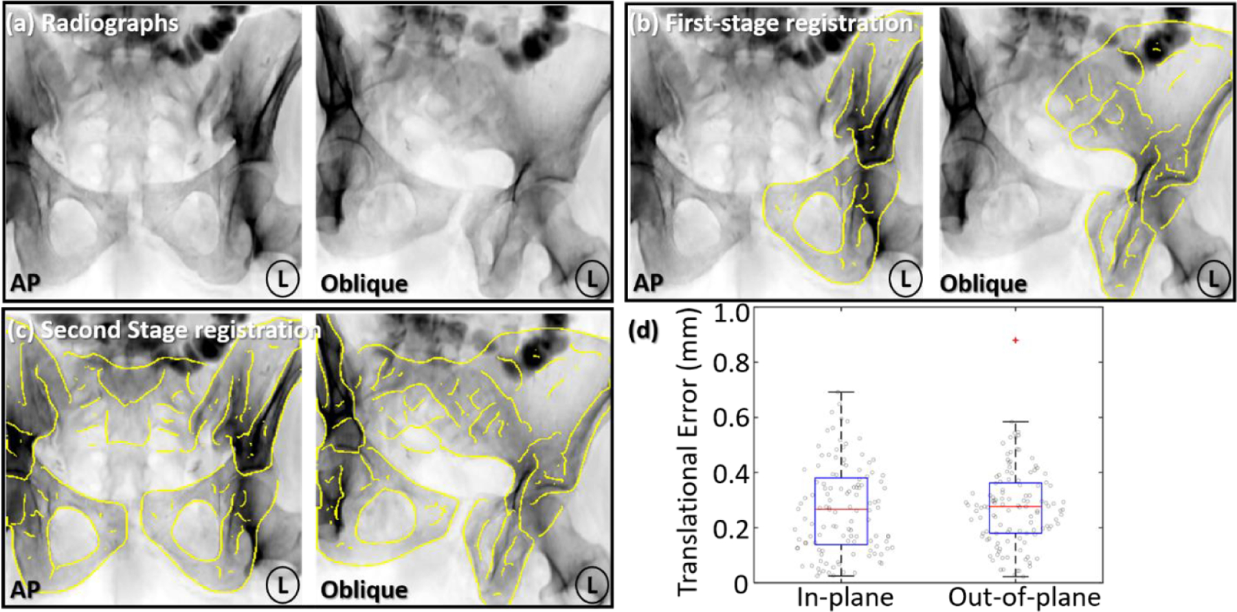
Multi-body 3D–2D registration accuracy in the simulation study. (a) Example AP and oblique radiographs (orbit 30° and tilt −20°) with dislocation of the left innominate bone. (b) Yellow DRR Canny edges of the left innominate after first-stage registration overlaid on the radiograph, resolving its pose with respect to the x-ray system. (c) Canny edges of three pelvic bones after the second-stage registration overlaid onto the radiographs, resolving the poses of all three bones with respect to each other. (d) In-plane and out-of-plane translational error in the multi-body 3D–2D registration after two-stage registration.
The capture range of the registration algorithm is characterized in figure 7 in terms of the translation error measured as a function of initialization error. For each case, 0 mm on the horizontal axis represents initializing the 3D model at the ground truth location, and the dashed horizontal line indicates 4 mm translational error. In this work, the capture range was defined as the range of initialization error in which registration error was below 4 mm (consistent with residual errors above which long-term prognosis of complications is poor (Smith et al 2005, Shillito et al 2014)). The in-plane capture range (x, z) of registration was measured to be around ±50 mm, beyond which the method did not reliably converge to the correct solution due to image gradients moving out of the radiographic scene. In the out-of-plane direction (related to the magnification of the DRRs), however, the capture range was even more robust, yielding ±120 mm. A possible explanation of the robustness is that the overall alignment of the multi-object DRRs to the radiographic anatomy is maintained for a wider range of displacement in the out-of-plane direction (i.e. salient image gradients do not leave the FOV). The plateaus in y and z directions as shown in figures 7(b) and (c) were due to the absence of anatomical structures in the direction of initialization error, which allowed the registration to converge to a similar solution. As shown in figures 7(d)–(f) for rotations, the in-plane rotation capture range was shown to be significantly larger (±50°) compared to the out-of-plane rotation capture ranges (±30°). One reason for narrower out-of-plane rotational capture range is that out-of-plane rotations correpond to shallower dimensions of the search space that are more susceptible to noise and local minima. Considering the size of the pelvis, the result suggested a high degree of robustness to initialization error in all three directions and the potential feasibility for clinical application without time-consuming manual initialization.
Figure 7.

Capture range measurement characterizing the robustness of multi-body 3D–2D registration to initialization error in translations ((a) in-plane direction x, (b) in-plane direction z, and (c) out-of-plane direction y) as well as rotations ((d) in-plane direction rx, (e) out-of-plane direction rz, and (f) out-of-plane direction rx). The horizontal dashed line indicates 4 mm translational error, below which the capture range was defined.
3.2. Phantom study
ASM segmentation of MDCT images of the phantom achieved surface RMSD of median 2.5 mm and overall Dice Coefficient of 0.89. The accuracy was slightly worse than that in the simulation study, presumably due to differences between the (somewhat unrealistic, idealized) shape of the simple phantom compared to that of real human pelves. A lack of heterogeneous interior bone gradients in the phantom may also contribute to a decrease in accuracy. Nonetheless, the segmented surfaces were sufficiently accurate for pose definition in SPM target pose estimation.
Figure 8 summarizes the accuracy of multi-body 3D–2D registration to two radiographic views in the phantom study. Figures 8(a) and (b) shows example AP and oblique (orbital 30° and tilt 10°) radiographs with moderate dislocation (~12 mm) of the left innominate bone. DRR Canny edges (yellow) of the three bones overlaid onto the radiograph show close alignment to the anatomy. TRE after registration is plotted in figure 8(c), with median of 1.8 mm (0.8 mm IQR) (in-plane) and 1.6 mm (2.1 mm IQR) (out-of-plane). The out-of-plane IQR was higher due to limited depth information for some combinations of radiographic views (e.g. (0, 0) and (0, 10) views). In addition, errors in 3D bone model definition arising from ASM segmentation errors could result in local minima, especially in the out-of-plane direction for cases of limited depth resolution. The overall TRE exhibited median of 2.5 mm (1.5 mm IQR), within reasonable accuracy for orthopaedic surgical applications (Smith et al 2005, Shillito et al 2014).
Figure 8.

Multi-body 3D–2D registration in the phantom study with dislocation of the left innominate bone. (a), (b) Radiographs at two C-arm views with registered DRR Canny edge overlay. Cyan and yellow points mark the fiducials on the radiographs and projected via the DRRs, respectively. (c) In-plane and out-of-plane registration error from 3D–2D registration.
The sensitivity of multi-body 3D–2D registration to simulated image noise (dose) is summarized in figure 9. Figures 9(a)–(c) shows radiographs at the nominal 50 μGy/frame, 5 μGy/frame and 0.5 μGy/frame dose level, respectively. DRR Canny edges after registration overlaid on the radiographs show accurate registration at both 50 μGy/frame and 5 μGy/frame, which is consistent with the TRE plot in figure 9(d). A fairly weak dependence was observed with dose down to ~5 μGy/frame, below which TRE increases sharply as quantum noise dominates the image. Registration accuracy with TRE < 4 mm (horizontal dashed line) at doses as low as 5 μGy/frame suggests the possibility of reducing fluoroscopy dose while maintaining guidance accuracy.
Figure 9.

3D–2D registration accuracy as a function of radiographic dose. (a) Radiographs at nominal dose of 50 μGy/frame, with yellow DRR Canny edges after registration. (b), (c) Simulated low dose radiographs at 5 μGy/frame (10% of nominal dose) and 0.5 μGy/frame (1% of nominal dose), respectively, with DRR Canny edges (yellow) after registration. (d) Registration accuracy (TRE) measured as a function of dose.
3.3. Reader study
Qualitative evaluation of the clinical acceptability of target reduction by an orthopaedic surgeon is summarized in table 1. In the experimental group, dislocations were reliably detected by the surgeon, who judged (2/6) cases as ‘mild’, (2/6) as ‘moderate’, and (2/6) as ‘severe’, increasing in proportion to the dislocation magnitude. In the 6 corresponding cases after SPMCC reduction, (5/6) were assessed as healthy and (1/6) was rated as ‘mild’ dislocation; all cases were judged to have improved in comparison to the initial, dislocated state. The experimental finding was comparable to the control group (non-dislocated pelves), in which (5/6) healthy cases were judged to be healthy, and (1/6) was rated as ‘mild’ dislocation. The study suggests that the method estimates the target reduction pose at a level that is clinically indistinguishable (within intra-observer variability) from a natural, healthy pelvis.
Table 1.
Evaluation of target reduction (and healthy subjects) by an orthopaedic trauma surgeon. The top row (experimental/dislocated) shows the surgeon’s assessment of dislocation severity. The second row (experimental/reduced) shows the surgeon’s assessment after reduction by an amount estimated by the proposed method, which was found to agree with the third row (control), which shows the surgeon’s assessment of dislocation in natural, healthy (non-dislocated) pelves.
| Group | Healthy | Mild | Moderate | Severe | |
|---|---|---|---|---|---|
| Experimental | Dislocated | 0 | 2 | 2 | 2 |
| Reduced | 5 | 1 | 0 | 0 | |
| Control | 5 | 1 | 0 | 0 | |
The case that was rated as ‘mild’ in the experimental reduced group and the case that was rated as ‘mild’ in the control group are further illustrated in figures 10(a) and (b). Figure 10(a) shows the experimental reduced case with a slight mismatch in height between the left and right pubis and a slightly narrow left SI joint. Even in the healthy control case, as shown in figure 10(b), a slight mismatch of the left and right pubis (the left side slightly higher than the right side) resulted in a misclassification by the surgeon. This finding suggests that misclassification of the dislocation could result from minor misalignment of the joints that are not clinically significant.
Figure 10.

Example reader study cases. (a) 3D rendering of the case in the experimental reduced group that was rated by the surgeon as ‘mild’ dislocation. (b) 3D rendering of the case in the control group (healthy undislocated pelvis) that was also rated by the surgeon as ‘mild’ dislocation.
3.4. Retrospective clinical feasibility study
Clinical feasibility was further evaluated in a case study involving a subject presenting with ‘open book’ separation of the PS and disruption of the left SI joint, as shown in the 3D rendering of the preoperative CT in figure 11(a). ASM segmentation of the preoperative CT achieved segmentation surface RMSD of median 1.4 mm and overall Dice Coefficient of 0.97, comparable to the result from the simulation study. Two radiographs (AP and inlet) were acquired immediately prior to reduction as shown in figures 11(b) and (c), and a 9 DoF multi-body 3D–2D registration was computed (9 DoF, since unlike the mobile C-arm, the mobile radiography system allows free variation of SDD and detector angulation). In both cases, DRR Canny edges of all three bones show reasonable alignment with the anatomy as depicted in the radiograph. The estimation of the target reduction is overlaid on the radiographs in green to illustrate the reduction needed to restore the left innominate bone to the correct pose.
Figure 11.

Multi-body 3D–2D registration and target reduction pose in a clinical case study. (a) 3D rendering of preoperative CT, showing ‘open book’ dislocation at the PS and SI joint. Intraoperative AP (b) and inlet (c) radiographs acquired prior to reduction and overlaid with Canny edges of DRRs from three registered bones. The reduction target is overlaid in green, providing guidance for surgical reduction. Anatomical landmarks defined in the radiographs are labeled in cyan, and those projected from 3D models are shown in yellow. Images in (d–f) show the progress of reduction, again overlaid with DRR Canny edges (yellow), reduction target (green), and anatomical landmarks.
Two intraoperative radiographs (AP and inlet) were subsequently acquired in the course of surgical reduction as shown in figures 11(e) and (f). Single-view, two-stage, multi-body, 9 DoF registrations were performed, and each demonstrates close alignment of anatomy after registration (evident in Canny edge overlay) despite the presence of surgical instrumentation in the image. The overall registration accuracy in the four images yielded PDE 3.1 mm (1.0 mm IQR) at the detector plane. A substantial component of this error is attributed to truth definition—i.e. the ability to define consistent, corresponding landmarks between the CT and radiographs, which exhibited ~1.5 mm intra-subject variability. Figures 11(e) and (f) shows the target reduction overlaid in green, providing a guide to further refinement of the reduction. The residual reduction is similarly evident in the orientation of the PS in the 3D-rendered CT image of figure 11(d).
Figure 12 summarizes the sensitivity of multi-body 3D–2D registration to the size of the radiograph FOV. Figure 12(a) shows example FOVs of size (190 × 190) mm2 with 10 randomly cropped boundaries overlaid (left subfigure). The Canny edges of registered DRRs from 10 trials are also overlaid (right subfigure). Over the range of FOV studied, accurate edge alignment was achieved within the FOV. However, the edge alignment outside the FOV could not be guaranteed, and the overall robustness of registration degraded as FOV size decreased, primarily due to decreased feature content in the images used for registration. The finding is evident in the Canny edge overlays in the right subfigures of figure 12(a): the PS (present in all cropped images) were well registered in all cases, whereas the right iliac crest (not present in every cropped image) was not accurately registered in all 10 trials. Figure 12(b) quantifies the observation in terms of PDE, showing a weak dependence on FOV above 170 mm (median PDE < 4 mm and IQR < 2 mm). For FOV smaller than 170 mm, PDE and variability increased sharply. Common intraoperative mobile C-arms, as used in the simulation and phantom study, have FOV ~300 × 300 mm2 (at the detector) corresponding to ~180–220 mm in the patient, as shown in the gray zone in figure 12(b). Thus, the FOV of such systems is near the minimum FOV requirement for accurate 3D–2D registration. Such findings support application of the method in scenarios with reduced FOV down to ~170 mm—e.g. fluoroscopy systems with limited FOV and/or collimation minimized to an area of interest to reduce dose and scatter—provided that enough salient anatomical features remain in the FOV to drive registration.
Figure 12.

Effect of radiographic FOV on 3D–2D registration accuracy. (a) Preoperative inlet radiograph with 10 randomly cropped FOV boundaries at 190 × 190 mm2. The 10 cropped FOVs are shown as color boxes on the left, and registered DRR Canny edges from 10 trials are overlaid on the right in the corresponding colors. (b) Registration accuracy (PDE) measured as a function of FOV size, with a range in FOV for the mobile C-arm used in the simulation and phantom study marked in gray.
Computation time is another import criterion for intraoperative guidance. Fluoroscopy-guided orthopaedic surgery often relies on step-and-shoot workflow in which surgeons acquire a single fluoroscopic view that is used to assess anatomy before acquiring a subsequent view (cf continuous fluoroscopy). Table 2 summarizes computation times for each step of the preoperative and intraoperative process. Preoperative runtime (ASM segmentation and reduction pose estimation) was ~4 min in total, which does not bear on intraoperative workflow—a planning step conducted prior to the case. Intraoperative runtime includes first and second stage of 3D–2D registration and augmentation/overlay, with total runtime of ~2 min for the first fluoroscopic image acquired in the procedure. For subsequent registrations, the first stage registration can be omitted, reducing runtime to ~40 s. The reported runtime correspond to a basic research implementation on a single GPU and further optimization and acceleration is anticipated to bring runtime suitable for workflow requirement.
Table 2.
Computation time of the preoperative and intraoperative segmentation and registration steps.
| Preoperative runtime (mean ± std) (s) | Intraoperative runtime (mean ± std) (s) | ||
|---|---|---|---|
| ASM Segmentation | 122.0 ± 5.7 | 3D–2D Registration: First Stage | 78.6 ± 29.2 |
| Pose Estimation | 116.2 ± 10.5 | 3D–2D Registration: Second Stage | 40.0 ± 11.5 |
| Fluoroscopy Augmentation | 0.2 ± 0.1 | ||
4. Discussion and conclusion
An algorithm for automatic estimation of target reduction pose and 3D–2D guidance of pelvic reduction surgery was reported. The method involves automatic segmentation of pelvic bones in preoperative CT using SSM, with experiments demonstrating segmentation accuracy of 1.4–1.8 mm (median surface RMSD) in the simulation and clinical feasibility studies. Estimation of the target reduction pose using the SPMCC method yielded ~2 mm translational and ~2° rotational error in the simulation study. The system solves a two-stage multi-body 3D–2D registration with or without knowledge of the x-ray system projection geometry (i.e. 6 or 9 DoF, respectively) to track multiple, semi-independently moving pelvic bones in intraoperative fluoroscopy/radiography. Registrations demonstrated sub-millimeter transformation error in both in-plane and out-of-plane directions in the simulation study. In the phantom study, 3D–2D registration achieved 2.5 mm overall TRE in the 3D coordinates of the patient, whereas in the clinical study, registration achieved 3.1 mm PDE at the detector plane. The system was also shown to be robust to initialization error (~±50 mm and ±120 mm capture range in- and out-of-plane, respectively), radiation dose (~one order of magnitude lower than the nominal dose of a fluoroscopic frame), and FOV size (down to ~170 × 170 mm2).
The accuracy of the registration algorithm was found to be dependent in part on the accuracy of ASM segmentation. As reported in previous work (Han et al 2019), the ASM segmentation is susceptible to errors (up to ~4 mm surface RMSD) in high curvature regions of the pelvis, which could negatively affect downstream target pose estimation and 3D–2D registration. The effect was mitigated somewhat in the current work using 3D segmentation models with CT attenuation coefficient from the original CT within the segmented surfaces. More sophisticated segmentation algorithms, such as using hierarchical SSM (Cerrolaza et al 2012), graph-cut optimization (Seim et al 2008), or deep learning methods (Al Arif et al 2018) may improve segmentation accuracy and the overall accuracy of registration and target pose estimation.
In the current implementation of multi-body 3D–2D registration, the transformations among multiple bones was solved in parallel without accounting for the inter-body relationship. In some scenarios, such as LAT or oblique radiographic views depicting a complex overlap of 3D shapes, misregistration could occur due to overlap of multiple bones in 3D. In addition, the DRR edges from one bone could be registered to the opposing joint surface of another bone due to the overall shape similarity in 2D. Future investigation could involve multi-body collision constraints within the 3D–2D registration to confine the search space and improve robustness in registering to such difficult radiographic views.
The experiments in the current work are not without limitations. In the phantom study, a simple SawBones phantom was used without soft-tissue structures or bowel gas in the projection images. The water tank in which the phantom was submerged, however, did present attenuation comparable to medium body habitus, giving an appropriate exposure level and realistic magnitude of image noise. Increased error observed in the phantom study was likely due to the somewhat unrealistic correspondence of the Sawbones phantom to the natural shape and image texture of real human pelves. For example, the highest density gradient in the phantom was related to the radiopaque shell instead of a more realistic subperiosteal layer of cortical bone. A more realistic phantom (including natural bone as well as soft-tissue heterogeneities surrounding the pelvis) and/or cadaver studies are the subject of further investigation.
Moreover, while the clinical study involved only one subject as a case study and initial investigation of feasibility, the case included multiple image instances (both CT and radiographs) that presented numerous aspects pertinent to the method, including a large magnitude of dislocation and the presence of interventional tools in the radiographs (content mismatch between CT and radiographs). Therefore, the study was sufficient to demonstrate basic feasibility of the proposed method and provided a basis for preliminary investigation of dependence on FOV size. Instead of evaluating registration error in terms of 2D PDE, 3D evaluation of the intraoperative bone poses is the subject of future work in which intraoperative CT or CBCT is available. For evaluation of the method in a more comprehensive clinical dataset and application to fluoroscopy systems using an x-ray image intensifier, an additional image distortion correction (Soimu et al 2003, Gutírrez et al 2008) common is likely warranted.
The preoperative segmentation and estimation of target reduction pose were computed with a runtime of ~4 min, which is well within the requirements of preoperative workflow. The (intraoperative) multi-body 3D–2D registration required a runtime of ~1–2 min, depending on the availability of x-ray system geometry and initialization error. Practical implementation within the rapid workflow requirements of trauma surgery will require runtime acceleration, which could potentially be accomplished using a number of methods currently being developed. For example, ongoing work considers a cascade of optimizers, with (slower, more robust) derivative-free CMA-ES performed at coarse-resolution, and refining with a (faster) derivative-based optimization at finer resolution (Grupp et al 2019). Alternatively (or in combination), the voxelized 3D model image could be converted to a more compact volumetric tetrahedral mesh representation for more efficient forward projection and volume transformation computation.
Overall, the method for guidance of pelvic reduction demonstrated accurate and robust performance in a variety of scenarios in simulation, phantom, and a clinical study. The resulting target pose estimation and multi-body 3D–2D registration provides an accurate means of preoperative planning and 3D–2D guidance for fluoroscopically guided reduction of pelvic trauma—specifically, dislocation. The solution offers the potential for application in mainstream trauma surgery, since it uses images already routinely acquired in current clinical workflow and does not introduce additional hardware, imaging, or tracking systems. The system has the potential to improve surgical accuracy (and hopefully the associated clinical outcomes) in treatment of pelvic trauma, reduce radiation dose associated with trial-and-error ‘fluoro hunting,’ and provide a basis for QA of the surgical product (i.e. quantitative assessment of bone reduction as achieved in the OR, compared to the SPM target reduction). Future work includes translation and validation of the method in a more comprehensive clinical dataset and generalization to other anatomical sites, such as hip and shoulder dislocation. In addition, ongoing work involves incorporating both pelvic dislocation and pelvic bone fracture into the proposed guidance framework (Han et al 2020).
Acknowledgments
This research was supported by NIH Grant R01-EB-017226 and academic-industry partnership with Siemens Healthineers (Forcheim, Germany).
References
- Al Arif SMMR, Knapp K and Slabaugh G 2018. Shape-aware deep convolutional neural network for vertebrae segmentation Computational Methods and Clinical Applications in Musculoskeletal Imaging (MSKI 2017). Lecture Notes in Computer Science, vol 10734 ed Glocker B, Yao J, Vrtovec T, Frangi A and Zheng G (Berlin: Springer; ) pp 12–24 [Google Scholar]
- Bossa MN and Olmos S 2006. Statistical model of similarity transformations: building a multi-object pose 2006 Conf. on Computer Vision and Pattern Recognition Workshop (CVPRW’06) (Piscataway, NJ: IEEE) p 59 [Google Scholar]
- Brehler M, Thawait G, Kaplan J, Ramsay J, Tanaka MJ, Demehri S, Siewerdsen JH and Zbijewski W 2019. Atlas-based algorithm for automatic anatomical measurements in the knee J. Med. Imaging 6 1 [DOI] [PMC free article] [PubMed] [Google Scholar]
- Cerrolaza JJ, Villanueva A and Cabeza R 2012. Hierarchical statistical shape models of multiobject anatomical structures: application to brain MRI IEEE Trans. Med. Imaging 31 713–24 [DOI] [PubMed] [Google Scholar]
- Çıçek H, Keskın HL, Tuhanıoğlu Ü, Kiliçarslan K and Oğur HU 2015. Simultaneous disruption of the pubic symphysis and sacroiliac joint during vaginal birth Case Rep. Orthop 2015 1–5 [DOI] [PMC free article] [PubMed] [Google Scholar]
- Cimerman M and Kristan A 2007. Preoperative planning in pelvic and acetabular surgery: the value of advanced computerised planning modules Injury 38 442–9 [DOI] [PubMed] [Google Scholar]
- Combes B, Hennessy R, Waddington J, Roberts N and Prima S 2008. Automatic symmetry plane estimation of bilateral objects in point clouds 2008 IEEE Conf. on Computer Vision and Pattern Recognition (Piscataway, NJ: IEEE) pp 1–8 [Google Scholar]
- Cootes TF, Taylor CJ, Cooper DH and Graham J 1995. Active shape models-their training and application Comput. Vis. Image Underst 61 38–59 [Google Scholar]
- De Silva T, Uneri A, Ketcha MD, Reaungamornrat S, Kleinszig G, Vogt S, Aygun N, Lo S-F, Wolinsky J-P and Siewerdsen JH 2016. 3D–2D image registration for target localization in spine surgery: investigation of similarity metrics providing robustness to content mismatch Phys. Med. Biol 61 3009. [DOI] [PMC free article] [PubMed] [Google Scholar]
- Dunn AW and Morris DH 1968. Fractures and dislocations of the pelvis J. Bone Joint Surg 50 1639–48 [PubMed] [Google Scholar]
- Fletcher PT, Lu C, Pizer SM and Joshi S 2004. Principal geodesic analysis for the study of nonlinear statistics of shape IEEE Trans. Med. Imaging 23 995–1005 [DOI] [PubMed] [Google Scholar]
- Goerres J. et al. Planning, guidance, and quality assurance of pelvic screw placement using deformable image registration. Phys. Med. Biol. 2017;62:9018. doi: 10.1088/1361-6560/aa954f. [DOI] [PMC free article] [PubMed] [Google Scholar]
- Gorczowski K, Styner M, Jeong JY, Marron JS, Piven J, Hazlett HC, Pizer SM and Gerig G 2010. Multi-object analysis of volume, pose, and shape using statistical discrimination IEEE Trans. Pattern Anal. Mach. Intell 32 652–61 [DOI] [PMC free article] [PubMed] [Google Scholar]
- Grupp RB, Hegeman R, Murphy R, Alexander C, Otake Y, Mcarthur B, Armand M and Taylor RH 2019. Pose estimation of periacetabular osteotomy fragments with intraoperative x-ray navigation IEEE Trans. Biomed. Eng 67 441–52 [DOI] [PMC free article] [PubMed] [Google Scholar]
- Gutírrez LF, Ozturk C, Mcveigh ER and Lederman RJ 2008. A practical global distortion correction method for an image intensifier based x-ray fluoroscopy system Med. Phys 35 997–1007 [DOI] [PMC free article] [PubMed] [Google Scholar]
- Halawi MJ 2016. Pelvic ring injuries: surgical management and long-term outcomes J. Clin. Orthop. Trauma 7 1–6 [DOI] [PMC free article] [PubMed] [Google Scholar]
- Han R, Uneri A, De Silva T, Ketcha M, Goerres J, Vogt S, Kleinszig G, Osgood G and Siewerdsen JH 2019. Atlas-based automatic planning and 3D–2D fluoroscopic guidance in pelvic trauma surgery Phys. Med. Biol 64 95022. [DOI] [PMC free article] [PubMed] [Google Scholar]
- Han R. et al. Multi-body registration for fracture reduction in orthopaedic trauma surgery. Proc. SPIE. 2020;11315:113150F. [Google Scholar]
- Hansen N, Müller SD and Koumoutsakos P 2003. Reducing the time complexity of the derandomized evolution strategy with covariance matrix adaptation (CMA-ES) Evol. Comput 11 1–18 [DOI] [PubMed] [Google Scholar]
- Hermann E, Faure F and Raffin B 2008. Ray-traced collision detection for deformable bodies 3rd Int. Conf. on Computer Graphics Theory and Applications (GRAPP 2008) (available at: https://hal.inria.fr/inria-00319404v1) [Google Scholar]
- Holdsworth FW 2012. The classic: dislocation and fracture-dislocation of the pelvis Clin. Orthop. Relat. Res 470 2085–9 [DOI] [PMC free article] [PubMed] [Google Scholar]
- Ketcha MD, De Silva T, Uneri A, Jacobson MW, Goerres J, Kleinszig G, Vogt S, Wolinsky JP and Siewerdsen JH 2017. Multi-stage 3D–2D registration for correction of anatomical deformation in image-guided spine surgery Phys. Med. Biol 62 4604. [DOI] [PMC free article] [PubMed] [Google Scholar]
- Kim W-Y, Jeong J-J, Kang H-V and Lee S-W 2016. Underestimated sacroiliac joint lesion on computed tomography in pelvic open-book injury: a case report Hip Pelvis 28 49. [DOI] [PMC free article] [PubMed] [Google Scholar]
- Koyanagi J, Sakai T, Yamazaki T, Watanabe T, Akiyama K, Sugano N, Yoshikawa H and Sugamoto K 2011. In vivo kinematic analysis of squatting after total hip arthroplasty Clin. Biomech 26 477–83 [DOI] [PubMed] [Google Scholar]
- Mahesh M 2001. Fluoroscopy: patient radiation exposure issues Radiogr. Rev. Publ. Radiol. Soc. North Am. Inc 21 1033–45 [DOI] [PubMed] [Google Scholar]
- Mezger U, Jendrewski C and Bartels M 2013. Navigation in surgery Langenbeck’s Arch. Surg 398 501–14 [DOI] [PMC free article] [PubMed] [Google Scholar]
- Mulhall KJ, Khan Y, Ahmed A, O’Farrell D, Burke TE and Moloney M 2002. Diastasis of the pubic symphysis peculiar to horse riders: modern aspects of pelvic pommel injuries Br. J. Sports Med 36 74–75 [DOI] [PMC free article] [PubMed] [Google Scholar]
- Otake Y, Wang AS, Webster Stayman J, Uneri A, Kleinszig G, Vogt S, Khanna AJ, Gokaslan ZL and Siewerdsen JH 2013. Robust 3D–2D image registration: application to spine interventions and vertebral labeling in the presence of anatomical deformation Phys. Med. Biol 58 8535. [DOI] [PMC free article] [PubMed] [Google Scholar]
- Ouadah S, Stayman JW, Gang GJ, Ehtiati T and Siewerdsen JH 2016. Self-calibration of cone-beam CT geometry using 3D–2D image registration Phys. Med. Biol 61 2613. [DOI] [PMC free article] [PubMed] [Google Scholar]
- Pahuta MA, Schemitsch EH, Backstein D, Papp S and Gofton W 2012. Virtual fracture carving improves understanding of a complex fracture: a randomized controlled study J. Bone Joint Surg. Am 94 e182. [DOI] [PubMed] [Google Scholar]
- Roth HR, Lu L, Seff A, Cherry KM, Hoffman J, Wang S, Liu J, Turkbey E and Summers RM 2014. A new 2.5D representation for lymph node detection using random sets of deep convolutional neural network observations Medical Image Computing and Computer-Assisted Intervention – MICCAI 2014. Lecture Notes in Computer Science, vol 8673 ed Golland P, Hata N, Barillot C, Hornegger J and Howe R (Berlin: Springer; ) pp 520–7 [DOI] [PMC free article] [PubMed] [Google Scholar]
- Schmid J and Chênes C 2015. Segmentation of x-ray images by 3D–2D registration based on multibody physics Computer Vision – ACCV 2014. Lecture Notes in Computer Science, vol 9004 ed Cremers D, Reid I, Saito H and Yang M-H (Berlin: Springer; ) pp 674–87 [Google Scholar]
- Seff A, Lu L, Cherry KM, Roth H, Liu J, Wang S, Hoffman J, Turkbey EB and Summers RM 2014. 2D view aggregation for lymph node detection using a shallow hierarchy of linear classifiers Medical Image Computing and Computer-Assisted Intervention – MICCAI 2014. Lecture Notes in Computer Science, vol 8673 ed Golland P, Hata N, Barillot C, Hornegger J and Howe R pp 544–52 [DOI] [PMC free article] [PubMed] [Google Scholar]
- Seim H, Kainmueller D, Heller M, Lamecker H, Zachow S and Hege H-C 2008. Automatic segmentation of the pelvic bones from CT data based on a statistical shape model VCBM 08: Eurographics Workshop on Visual Computing for Biomedicine pp 93–100 [Google Scholar]
- Seltzer S 1996. Tables of x-ray mass attenuation coefficients and mass energy-absorption coefficients NIST Standard Reference Database 126 ( 10.18434/T4D01F) [DOI] [Google Scholar]
- Shillito M, Linn M, Girard P and Schwartz A 2014. Anterior sacroiliac dislocation: a case report and review of the literature JBJS Case Connect. 4 e78. [DOI] [PubMed] [Google Scholar]
- Smith W, Shurnas P, Morgan S, Agudelo J, Luszko G, Knox EC and Georgopoulos G 2005. Clinical outcomes of unstable pelvic fractures in skeletally immature patients J. Bone Joint Surg. Am 87 2423–31 [DOI] [PubMed] [Google Scholar]
- Soimu D, Badea C and Pallikarakis N 2003. A novel approach for distortion correction for x-ray image intensifiers Comput. Med. Imaging Graph 27 79–85 [DOI] [PubMed] [Google Scholar]
- Steihaug T 1983. The conjugate gradient method and trust regions in large scale optimization SIAM J. Numer. Anal 20 626–37 [Google Scholar]
- Suero EM, Hüfner T, Stübig T, Krettek C and Citak M 2010. Use of a virtual 3D software for planning of tibial plateau fracture reconstruction Injury 41 589–91 [DOI] [PubMed] [Google Scholar]
- Tormenti MJ, Kostov DB, Gardner PA, Kanter AS, Spiro RM and Okonkwo DO 2010. Intraoperative computed tomography image-guided navigation for posterior thoracolumbar spinal instrumentation in spinal deformity surgery Neurosurg. Focus 28 1–6 [DOI] [PubMed] [Google Scholar]
- Uneri A. et al. Intraoperative evaluation of device placement in spine surgery using known-component 3D–2D image registration. Phys. Med. Biol. 2017;62:3330. doi: 10.1088/1361-6560/aa62c5. [DOI] [PMC free article] [PubMed] [Google Scholar]
- Uneri A, Otake Y, Wang AS, Kleinszig G, Vogt S, Khanna AJ and Siewerdsen JH 2014a. 3D–2D registration for surgical guidance: effect of projection view angles on registration accuracy Phys. Med. Biol 59 271. [DOI] [PMC free article] [PubMed] [Google Scholar]
- Uneri A, Wang AS, Otake Y, Kleinszig G, Vogt S, Khanna AJ, Gallia GL, Gokaslan ZL and Siewerdsen JH 2014b. Evaluation of low-dose limits in 3D–2D rigid registration for surgical guidance Phys. Med. Biol 59 5329. [DOI] [PubMed] [Google Scholar]
- Vidal R, Ma Y and Sastry SS 2016. Generalized Principal Component Analysis (New York: Springer; ) [DOI] [PubMed] [Google Scholar]
- Wang AS, Stayman JW, Otake Y, Vogt S, Kleinszig G, Khanna AJ, Gallia GL and Siewerdsen JH 2014. Low-dose preview for patient-specific, task-specific technique selection in cone-beam CT Med. Phys 41 71915. [DOI] [PMC free article] [PubMed] [Google Scholar]
- Waschke A, Walter J, Duenisch P, Reichart R, Kalff R and Ewald C 2013. CT-navigation versus fluoroscopy-guided placement of pedicle screws at the thoracolumbar spine: single center experience of 4,500 screws Eur. Spine J 22 654–60 [DOI] [PMC free article] [PubMed] [Google Scholar]
- Zhang Q, Chen W, Liu H, Su Y, Pan J and Zhang Y 2009. The anterior dislocation of the sacroiliac joint: a report of four cases and review of the literature and treatment algorism Arch. Orthop. Trauma Surg 129 941–7 [DOI] [PubMed] [Google Scholar]