

Abstract
Purposes:
Surgical reduction of pelvic fracture is a challenging procedure, and accurate restoration of natural morphology is essential to obtaining positive functional outcome. The procedure often requires extensive preoperative planning, long fluoroscopic exposure time, and trial-and-error to achieve accurate reduction. We report a multi-body registration framework for reduction planning using preoperative CT and intraoperative guidance using routine 2D fluoroscopy that could help address such challenges.
Method:
The framework starts with semi-automatic segmentation of fractured bone fragments in preoperative CT using continuous max-flow. For reduction planning, a multi-to-one registration is performed to register bone fragments to an adaptive template that adjusts to patient-specific bone shapes and poses. The framework further registers bone fragments to intraoperative fluoroscopy to provide 2D fluoroscopy guidance and/or 3D navigation relative to the reduction plan. The framework was investigated in three studies: (1) a simulation study of 40 CT images simulating three fracture categories (unilateral two-body, unilateral three-body, and bilateral two-body); (2) a proof-of-concept cadaver study to mimic clinical scenario; and (3) a retrospective clinical study investigating feasibility in three cases of increasing severity and accuracy requirement.
Results:
Segmentation of simulated pelvic fracture demonstrated Dice coefficient of 0.92 ± 0.06. Reduction planning using the adaptive template achieved 2-3 mm and 2-3° error for the three fracture categories, significantly better than planning based on mirroring of contralateral anatomy. 3D-2D registration yielded ~2 mm and 0.5° accuracy, providing accurate guidance with respect to the preoperative reduction plan. The cadaver study and retrospective clinical study demonstrated comparable accuracy: ~0.90 Dice coefficient in segmentation, ~3 mm accuracy in reduction planning, and ~2 mm accuracy in 3D-2D registration.
Conclusion:
The registration framework demonstrated planning and guidance accuracy within clinical requirements in both simulation and clinical feasibility studies for a broad range of fracture-dislocation patterns. Using routinely acquired preoperative CT and intraoperative fluoroscopy, the framework could improve the accuracy of pelvic fracture reduction, reduce radiation dose, and could integrate well with common clinical workflow without the need for additional navigation systems.
Keywords: Image-guided surgery, Image registration, 3D-2D registration, Statistical modeling, Surgical planning
1. Introduction
Pelvic fracture is a severe trauma injury that comprises up to 20% of blunt trauma (and 3% of all bone fractures) and is associated with high morbidity and mortality (Halawi, 2016; McMurtry et al., 1980). Pelvic fracture involves one or more bones of the pelvis and may include disruptions of ligamentous structures between these bones (i.e. sacroiliac (SI) joints and pubic symphysis (PS)), resulting in dislocations of pelvic bones (Huegli et al., 2009). High-energy trauma, such as motor vehicle accidents and falls from a height, often results in unstable pelvic fractures or fracture-dislocations that require prompt surgical intervention (Khurana et al., 2014). In Tile classification, such unstable fractures are classified into Type B and Type C depending on vertical stability (Tile, 2005). In an epidemiological study of 537 patients (Hermans et al., 2017), unstable fractures requiring surgical intervention consisted of 74.5% of total cases, among which 18.3% were bilateral fractures (Type B3 and C3). Additionally, comminuted and multi-fragment fractures (more than two bone fragments), consisted of 2% of total cases (Switzer et al., 2000), is a serious type of unstable fracture that can lead to significant complications.
Following diagnosis and planning in CT – often in the emergency setting – surgical intervention to treat unstable pelvic fractures typically involves open or closed reduction and fixation of bone fragments under x-ray fluoroscopy guidance. In such procedures, the fractured bone fragments are reduced to their natural anatomical orientations, but geometric misalignments comprise 30% of surgical reduction error (characterized by >5 mm residual displacement in pelvic ring fractures and >2 mm in acetabulum fractures) and are associated with long-term complications such as persistent pain, limb length discrepancy, and disability (Halvorson et al., 2014; Shillito et al., 2014; Smith et al., 2005). In comminuted fractures, smaller bone fragments that do not contribute to the overall stability of the pelvic ring or acetabulum are typically not surgically reduced or fixated – instead, left in place to heal without fixation. In this work, such small fragments were therefore not considered in the planning analysis, and the behavior of the method in such a case was examined in one clinical case in Section 5.4.2.
Fracture reduction is technically challenging and benefits from some form of preoperative planning. Reduction planning – the process of determining fractured bone fragments and the corresponding transformations to restore morphology – is conventionally carried out using preoperative CT interpreted qualitatively to form a “mental” plan. However, such an approach is not suitable to surgical navigation (e.g., 3D tracking) and fails to quantitatively assess the union of bone fragments, requiring surgeons to resort to trial-and-error to achieve the desired reduction (Schweizer et al., 2010). Computer-assisted manual 3D planning tools help to address such drawbacks by virtual manipulation of 3D bone models and quantification of mal-reduction (Cimerman and Kristan, 2007; Suero et al., 2010). For complex and comminuted fractures, however, manual 3D planning can be difficult and time-consuming with respect to the rapid trauma workflow: for example, an average time of 174.8 min was reported for manual planning of tibial plateau fracture using a 3D CAD tool (Suero et al., 2010).
Emerging semi-automatic and automatic methods provide the potential for more streamlined and quantitative planning. Such methods generally rely on segmentation of fractured bone fragments and planning of reduction transformations to restore the morphology of a single bone. Segmentation is either performed manually or semi-automatically using thresholding (Tassani et al., 2012), region growing (Fornaro et al., 2010; Lee et al., 2012) or watershed transforms (Shadid and Willis, 2013). Many preoperative reduction planning methods have been reported, including matching fracture lines with complementary surface characteristics (Willis et al., 2007; Zhou et al., 2009) and aligning bone fragments to a template mirrored from the healthy contralateral side (Fürnstahl et al., 2012). However, the former suffers from challenging fracture line definitions (typically of low intensity trabecular bones in CT) and the latter relies on an assumption of symmetry between contralateral aspects of the pelvis that is often not valid (e.g., natural shape differences between sides or – worse – bilateral trauma). To address such limitations, statistical shape models (SSMs) have also been used as the template for point-based registration between the SSM and bone fragments (Albrecht and Vetter, 2012; Han et al., 2020b). However, such methods rely on point correspondence between the SSM and bone fragments, a challenging task when the points on the fracture line are not included in the SSM. Furthermore, the aforementioned methods are limited to reduction of a single bone and do not account for reduction of a system of interrelated bones such as the pelvis (i.e., the left and right innominate bone as well as the sacrum). As utilized below, a statistical pose model (SPM) is established to statistically analyze the poses of multiple objects jointly in a nonlinear Lie group space (Bossa and Olmos, 2006; Fletcher et al., 2004).
Successful outcome of fracture reduction surgery also depends on accurate and precise intraoperative guidance (Fürnstahl et al., 2016). Due to the challenges of cognitive reckoning of the orientation of complex 3D fractures from 2D fluoroscopic projections, conventional reduction surgery under fluoroscopy guidance carries a steep learning curve, involves frequent trial-and-error, and extended fluoroscopy time (often >2 min) (Gras et al., 2010). Recent advances in computer-assisted image guidance, such as using surgical tracking and 3D intraoperative imaging, bring preoperative surgical planning into the operation to improve surgical precision and safety. Tracking and navigation approaches usually involve fiducial markers placed on the patient and interventional devices, allowing registration of preoperative imaging to the world coordinate frame during surgery; however, the use of navigation in orthopaedic trauma surgery is rare, due in part to the additional cost, equipment, and workflow associated with such systems. 2D fluoroscopic guidance is still a mainstay in orthopaedic trauma surgery, and methods for 3D-2D registration-based guidance offer an opportunity to register routinely acquired x-ray fluoroscopy images to preoperative 3D imaging. For example, image registration between preoperative CT and 2D fluoroscopy have been proposed for target localization and guidance in spine surgery (De Silva et al., 2016; Uneri et al., 2014). Existing registration methods, however, do not account for independent motions of multiple bones during the operation, presenting a source of geometric error that challenges conventional rigid registration methods. To address such limitations, a multi-scale 3D-2D image registration approach to account for rigid motions in orthopaedic surgery has been proposed (Han et al., 2020a). Another technique, 3D-2D reconstruction, has been proposed to directly reconstruct 3D bones from 2D radiographs using SSM for surgical planning (Balestra et al., 2014; Zheng et al., 2015). The SSM only models healthy, non-fractured bones, and have not been applied to 3D-2D reconstruction of fractured bones due to high variation in fracture patterns.
To address the challenges and streamline preoperative and intraoperative workflow, we propose a multi-body registration framework for pelvic reduction planning and guidance to address the most general cases of unstable pelvic fracture (Tile Type B and C, including comminuted fractures). Beginning with semi-automatic segmentation (via continuous max-flow) of fractured bone fragments in CT, a multi-to-one registration solves the reduction plan between bone fragments with an adaptive template that describes multi-body bone shapes and poses. The framework further registers bone fragments to intraoperative fluoroscopy to provide both 2D fluoroscopy guidance and 3D navigation relative to the reduction plan. The method offers to improve the accuracy of fracture reduction using 2D fluoroscopy already common in routine care, without additional devices or disruption to surgical workflow. The contributions of this work are:
A novel template, referred to as an adaptive template, is proposed as the reference image for reduction planning. The adaptive template combines SSM and SPM to describe shapes and poses of a system of bones. The adaptive template extends previous work (Albrecht and Vetter, 2012; Han et al., 2020b) from description of a single bone to a system of bones.
A novel multi-to-one registration is designed to register bone fragment segmentations obtained via multi-label continuous max-flow to an adaptive template. The registration simultaneously solves for reduction planning transformations and the adaptive template shape and pose parameters. The registration cost function is optimized using an alternating scheme between fragment alignment, shape adaptation, and pose adaptation.
The multi-body 3D-2D registration (Han et al., 2020a) is integrated with preoperative fracture reduction planning for the application of fracture reduction surgical navigation.
The proposed multi-body registration framework was validated in a leave-one-out simulation study (a total of 120 variations in pelvic fractures) and a clinical feasibility study comprising three classes of fracture of increasing difficulty and accuracy requirement. This paper is organized as follows: in Section 2, we review existing methods for pelvic segmentation, reduction planning, and 3D-2D registration; in Section 3, we describe the details of the proposed framework; experimental methods and results are presented in Sections 4 and 5, respectively; and conclusions and possible future directions are discussed in Section 6.
2. Related work
2.1. Image segmentation
Segmentation of bone fragments in CT is a difficult task due to the arbitrary shape, variable number of bone fragments and broad variation of fracture locations, challenging the application of priorknowledge (e.g., SSM or supervised deep learning), especially in comminuted fractures. Furthermore, bone fragments are not fully surrounded by dense cortical bone, and exposed trabecular bone at the edge of fragments often have comparable intensity to surrounding soft tissue. Bone fragments can also appear to be connected due to limited spatial resolution in the image and/or physical proximity / contact.
Many segmentation methods have been proposed to address one or more of the aforementioned challenges. (Lai et al., 2016; Ruikar et al., 2019) proposed 3D region-growing on pre-processed CT images to segment bone fragments based on input “seed points”. (Lee et al., 2012) extended the region-growing approach to a multi-label method that simultaneously solves for multiple fragments. However, manual separation of connected bone fragments is often required. (Fornaro et al., 2010) proposed a more automatic segmentation pipeline with adaptive thresholding for cortical bones, region growing for cancellous bone, and bone fragment separation based on graph-cut and “seed points”. However, the region-growing method relies on careful tuning of intensity threshold that can be sensitive to over-segmentation of soft tissue near trabecular bone edges and near joint space. A probabilistic watershed transform method was proposed to encode a priori estimation of the bone intensity distribution into the segmentation (Shadid and Willis, 2013). In the work reported below, we incorporate the advantages of multi-label segmentation and a priori intensity information into a multi-label graph-cut based segmentation using continuous max-flow (CMF) (Yuan et al., 2014) to simultaneously solve for segmentation and separation of multiple bone fragments based on input “seed points”. Compared to other segmentation methods, CMF allows incorporation of many cost functions (e.g., distance to seed points and incorporation of a prior intensity constraint) into a single formulation and does not require ad-hoc post processing (e.g., manual fragment separation).
2.2. Reduction planning
Reduction planning is the process by which bone fragment segmentations are repositioned to approximate the original anatomy. A first category of reduction planning aims to match corresponding fracture planes and often involves interactive specification of surface regions used for matching (Willis et al., 2007; Zhou et al., 2009). Surface registration is performed to align fracture planes based on proximity and complementary surface characteristics. However, segmentation accuracy near the fractures is often low due to poor contrast between trabecular bone and soft tissue, resulting in surface registration errors. In addition, bone fracture surfaces may share matches with more than one fragment, increasing the difficulty of registration, especially in comminuted fractures (Jiménez-Delgado et al., 2016).
A second category of reduction planning uses some model of healthy bone as a template to align bone fragments. (Fürnstahl et al., 2012; Okada et al., 2009) used the healthy contralateral bone as the template for reduction planning of the humerus and femur, respectively. However, using the contralateral side is often not applicable, especially in pelvic trauma that involves a high frequency of bilateral trauma. In addition, shape differences between symmetrical bones can exist (Gnat et al., 2009). To compensate for the contralateral asymmetry, feature matching on the fracture lines were included to refine the reduction (Fürnstahl et al., 2012; Okada et al., 2009; Vlachopoulos et al., 2018). The fracture line matching technique has limited application in comminuted fracture, however, because small fragments are not surgically reduced. Such small fragments, often hard to identify and segment, and more prone to segmentation error than larger bones, are required to perform fracture line matching. Such complications challenge the method, especially when the small fragments are not properly treated, resulting in matching of noncorresponding fracture lines. Other authors used a more statistical approach in generating the template of healthy bone. (Albrecht and Vetter, 2012; Moghari and Abolmaesumi, 2008) constructed an SSM based on an atlas of bone surface meshes and performed point registration between bone fragments and the template to solve for the transformations in reduction planning. (Han et al., 2020b) proposed an alternative SSM approach that used volumetric representation of the SSM for single bone fracture reduction planning to take advantage of more robust image-domain registration.
While methods using SSM templates solve the reduction planning problem of a single bone, the target pose of the bone with respect to its surrounding anatomy has not been considered. Articulated statistical shape model was proposed in the context of segmentation, which jointly models bone shapes of pelvis and proximal femur and the rotational motion of the femur around the hip joint with the assumption that the pelvis was fixed (Balestra et al., 2014; Kainmueller et al., 2009). Meanwhile, (Fletcher et al., 2004) addressed the problem from a different perspective by analyzing shapes and poses of multiple brain structures using Principal Geodesic Analysis. The model considers poses of not only rotation, but also translation and scaling. (Bossa and Olmos, 2006; Gorczowski et al., 2010) further extended the work to SPM that directly models the pose transformations. (Han et al., 2020a) adapted SPM to the reduction planning of pelvic dislocation by inference of reduction transformation for dislocated, non-fractured bones.
In this work, we build upon previous works on dislocation reduction planning (Han et al., 2020a) and single bone fracture reduction planning (Han et al., 2020b) to combine SSM and SPM into a single model for fracture reduction planning in the context multiple bones. To our knowledge, this is the first work that addresses reduction planning in the context of multiple bones and includes descriptions of both shapes and poses of the bones. In contrast to point registration, the method in this work is solved in the volumetric image domain to avoid defining point correspondence and to make use of inter-object operations such as intersection and union for better registration regularization.
2.3. 3D-2D registration
Intraoperative navigation using 3D-2D registration has been developed to register routinely acquired 2D x-ray fluoroscopy images to preoperative 3D imaging as a basis for surgical guidance. For example, (De Silva et al., 2016; Otake et al., 2013; Uneri et al., 2014a, 2014b) demonstrated 3D-2D registration between CT and fluoroscopy for target localization in spine surgery. The same method was also applied in pelvic trauma surgery to augment fluoroscopy with preoperatively determined 3D planning information (Han et al., 2019). However, these methods do not account for the motion of bones imparted after 3D imaging (e.g., due to patient motion and/or surgical reduction). (Koyanagi et al., 2011; Schmid and Chênes, 2015) addressed the limitation by employing multi-body registration of landmark points extracted from the 3D and 2D images. Alternatively, (Ketcha et al., 2017) proposed a piecewise rigid image-based registration using multiple masks of vertebra to account for deformation in spine surgery. (Han et al., 2020a) extended previous work by registering multiple 3D segmentations to fluoroscopy to solve for the motion of pelvic dislocations (i.e., the motion of multiple bones with respect to joint spaces). This work adapts the work from (Han et al., 2020a) to solve for multiple fractured bone fragments.
3. Algorithmic methods
The proposed multi-body registration framework for pelvic fracture reduction is illustrated in Fig. 1. The two main parts of the framework are: (1) preoperative segmentation of bone fragments and calculation of the target transformations of bone fragments after surgical reduction; and (2) intraoperative guidance of bone fragment reduction by navigation relative to 2D fluoroscopy or 3D CT. Both parts of framework use 3D image representations for easier cost function evaluation and more robust image-based registration. The top (preoperative) branch in Fig. 1 illustrates the segmentation of multiple bone fragments from a patient CT image via the continuous max-flow algorithm. An adaptive template is constructed consisting of a statistical shape model (SSM) and statistical pose model (SPM) to adapt to patient-specific bone shapes and poses. Segmentations of bone fragments are registered to the adaptive template in an alternating optimization to estimate the target transformations for reduction planning.
Fig. 1.

Process flowchart of multi-body registration for pelvic fracture reduction planning and guidance, addressing not only dislocations of SI joint and PS (Han et al., 2020a) but also multi-fragment fractures. Preoperative registration steps (segmentation and fracture reduction planning) are in the top branch (gray). Note that the SPM in the adaptive template describes multi-body poses and extends from single bone modeling (Han et al., 2020b) to multiple bone modeling. Intraoperative steps (multi-body 3D-2D registration and 2D/3D guidance) are in the bottom branch (blue).
The bottom (intraoperative) branch of Fig. 1 shows the bone fragment segmentations mapped to one or more 2D fluoroscopic images via a two-step multi-body 3D-2D registration to provide estimations of x-ray system geometry and 3D poses of bone fragments. Both 2D guidance (i.e., visualization in fluoroscopy) and 3D guidance (i.e., visualization in the 3D model) are possible via the 3D-2D registration and preoperative reduction plan. In 2D guidance, preoperative plans can be mapped to the fluoroscopic scene to augment the fluoroscopic view and provide guidance in a form that is familiar to orthopaedic surgeons. In 3D guidance, the position of bone fragments can be visualized relative to the preoperative CT and reduction plan. In either 2D or 3D guidance, the target pose estimations from reduction planning augment the surgeon’s determination of the extent to which the current reduction is within an acceptable range of the desired reduction.
3.1. Fractured bone segmentation on CT images
A semi-automatic segmentation method was implemented to segment bone fragments in preoperative CT images of fractured pelves, requiring only an input “seed point” for each bone fragment of interest. The seed points are manually identified by the user clicking on a voxel within each bone fragment. The segmentation is formulated as an N-label continuous max-flow problem (Yuan et al., 2014) such that each bone fragment and the background are segmented into different labels, according to the cost function:
| (1) |
where un, n = 1, 2, …, N is a membership function with value between 0 and 1 that defines whether a voxel x belongs to the nth label. A higher value represents a higher likelihood of the voxel belonging to the corresponding label. D1 and D2 are the costs of foreground and background voxels and are designed following (Han et al., 2020b). D1 is the cost associated with the likelihood of the voxel being bone according to its CT Hounsfield unit (HU) and a priori intensity distribution learned from previous pelvis CT images. A gaussian mixture model with two components was chosen for the intensity distribution of pelvic bone (cortical and trabecular components). The distribution D2 is the cost associated with the background voxels and is defined as the gradient-weighted distance from input seed points, which is higher when the path between the voxel and input seed points of the corresponding label traverses an image gradient (hence traversing a bone edge) and is therefore considered to be outside the bone.
The last term in the integrand of Eq. (1) is a regularization to enforce the smoothness of the segmentation by penalizing large segmentation gradient, ∇u(x):
| (2) |
where ∇I is the CT image gradient. β and γ are scalar parameters to control the relative strength of the three terms in the objective of Eq. (1). The N-label objective function was solved to obtain n-1 bone fragment segmentations S(n), n = 1, 2, …, N – 1. In this work, β and γ were chosen to be 0.5 and 3.0, respectively, based on (Han et al., 2020b). The segmentation requires minimal user interaction, with as few as one seed point defined for each bone fragment in the CT image. In cases where two or more bone fragments are connected, additional seed points may be placed at the boundaries of the fragments.
3.2. Multi-body 3D registration for fracture reduction planning
3.2.1. An adaptive template for target pose definition
A statistical template of the pelvis is constructed to model multi-body bone shapes and poses, with adaptable shape and pose parameters to be adapted to patient-specific anatomy. This “adaptive template” serves as a fixed image onto which the segmentations of bone fragments are registered for fracture reduction planning. An open-source pelvis atlas (Han et al., 2019) comprised of 40 CT images and corresponding segmentations of left/right innominate bone (ilium, ischium, and pubis) and sacrum was used for the adaptive template construction. The bone shapes are modeled in terms of an SSM by incorporating shape variations of each bone via principal component analysis (PCA). The bone poses are modeled in terms of a SPM by computing the statistical variations of the anatomical poses among the system of bones.
The SSM construction follows the work of (Luthi et al., 2018; Rueckert et al., 2003), which models the deformation field from the mean shape. The SSM of each bone is modeled separately by first aligning bone segmentations via rigid image registration. From a randomly selected segmentation reference Ir in the atlas of A images, a deformable registration using free-form deformation (FFD) is performed to other segmentations in the atlas Ia, where a = 1, 2, …, A, a ≠ r, creating (N – 1) deformation fields ϕ (x) of the form (Schnabel et al., 2001):
| (3) |
where c denotes a 3D lattice of control points that parametrizes the deformation field, (i, j, k) denotes the indices of the control points, and (u, v, w) denotes the relative position of voxel x in the lattice coordinates. The deformation field is a 3D tensor product of the one-dimensional cubic B-splines Bl, Bm, Bn. The FFD registration between two segmentations is solved using gradient descent minimization with a mean-squared-difference similarity metric. ϕ(x) maps each control point in the reference segmentation to the corresponding point in the target segmentation. A statistical analysis of ϕ(x) using PCA can model the shape variation of the bone segmentations, which is parametrized by the control point vectors c:
| (4) |
where is the average control point vector, P is the matrix composed from the SSM principal component vectors, and vSSM is the model parameter vector. Such a procedure is closely related to the standard SSM concept, which applies a PCA to corresponding points on the surface of the anatomy, but no manual definition of correspondence landmarks is required. For notational simplicity, the function relating the control points vector c to the deformation field ϕ (Eq. (3)) and the deformed image Ir ∘ ϕ(x) is denoted as ψ(·). The standard deviation of the control points deformation, quantifying the variability of the SSM, is around 3.3 mm.
After modeling individual bone shape via SSM, the three pelvic bones (sacrum and left/right innominate) are treated as a multibody system in which the poses are jointly modeled via SPM. SPM is defined by the statistical variation of the poses (i.e., the similarity transformations with respect to the mean) and can be used to extrapolate the pose of a dislocated bone based on the other bone poses. Any 3D similarity transformation can be modeled linearly in the Lie group space (via matrix logarithm) by seven parameters b = [txtytzrxryrz log s]T (Bossa and Olmos, 2006; Han et al., 2020a), where (tx, ty, tz) are translation parameters, (rx, ry, rz) ∈ SO(3) are rotational parameters belonging to the 3D rotation group, and s is the scaling parameter. Compared to the non-linear Euler angle or transformation matrix representation, the Lie group representation of the rotational parameters is linear and thus more suitable for PCA (Fletcher et al., 2004). The b vector in the Lie group space is equivalent to the matrix representation of the similarity transformation in the Euclidean space. Hence, multi-body poses can be concatenated into a single vector B for PCA in the Lie group space:
| (5) |
where is the average pose vector, Q is the covariance matrix composed from the SPM principal component vectors, and vSPM is the model parameter vector. For a system of L unfractured bones, the pose of the lth body can hence be computed from the pose vector via exponential mapping:
| (6) |
where [·]l are the indices corresponding to the lth body and expm (·) denotes the matrix exponential operation that converts the Lie group vector to Euclidean space transformation matrix.
In estimation of the target bone pose (e.g., the unknown target pose, BX, of the left innominate bone), the unknown bone pose can be estimated from the observed poses of undislocated bones BO (e.g. the sacrum and the right innominate) through an inference problem of the posterior model of the SPM (Albrecht et al., 2013):
| (7a) |
| (7b) |
| (7c) |
| (7d) |
where [·]O and [·]X are the indices of the undislocated and target bones, respectively. and Qc are the posterior mean and covariance matrix adjusted based on observed poses, and σ2 models the deviation of the inference poses from the model, computed according to (Albrecht et al., 2013). Eq. (7a) is solved using interior-point constrained optimization (Byrd et al., 2000) subject to the constraint that each entry of the SPM weight vector vi is within three standard deviations of the SPM eigenvalue λi. The average movement between the healthy pelvic bones is quantified by the standard deviation of the translational and rotational parameters in the SPM model. In terms of translations, the standard deviation ranges from 1.5 mm to 2.6 mm for the innominate bones and up to 5 mm translation in anterior-posterior / superior-inferior direction for the sacrum. In terms of rotations, the standard deviation ranges from 1° to 3° for the innominate bones in all directions and up to 5° for the sacrum in the sagittal plane. Empirically, minimal model intersection was observed within ±3λ.
3.2.2. Multi-body 3D registration for reduction planning
A novel multi-body 3D registration framework was developed for estimating the transformations of bone fragments to the desired reduction as a form of surgical planning. The registration addresses a multi-to-one problem that simultaneously solves for transformations of multiple bone fragments to align with the adaptive template and the parameters of the adaptive template to fit with the patient-specific anatomical shapes and poses. The registration is solved in the 3D image domain to take advantage of rich image information and simple inter-object operations such as intersection and union without definition of correspondence as in point- or mesh-based registrations (Albrecht and Vetter, 2012).
The fracture reduction planning solves the 6 degree-of-freedom (DoF) rigid transformations T(n) for bone fragments S(n), n = 1, …, N such that the fragments are well aligned with the adaptive template, which is modeled by SSM parameters , l = 1, 2, …, L and SPM parameters vSPM. SPM transformation matrices can be obtained from vSPM via Eq. (6). The cost function Creg combines the squared difference between the adaptive template Itemplate and the transformed bone fragments with a regularization term R to inhibit bone fragment collision / overlap:
| (8a) |
where the adaptive template image:
| (8b) |
is the summation of L healthy bone images converted from the SSM parameters via ψ (·) and transformed via SPM. The regularization R is the sum of overlap between any two fragments:
| (8c) |
with λ controlling the strength of the regularization and allowing small overlap between bone fragment segmentations. For small segmentation errors at the fracture plane, such tolerance improves accuracy compared to a hard threshold that forbids any overlap. In addition, the regularization keeps the cost function smooth. Since bone fragments S are represented as 3D binary images, the overlap can be easily computed by the sum of element-wise multiplication.
Direct minimization of Eq. (8a) is challenging due to the high dimensional, generally non-convex parameter space that is subject to local minima. To reduce the dimensionality, an alternating minimization approach is used that iteratively alternates among three stages: (1) registration of N bone fragments to the adaptive template to solve for the rigid transformations {T(n)}; (2) adaptation of the template shape (parametrized by of the SSM) to patient-specific shapes; and (3) adaptation of the template poses (parametrized by of the SPM).
Stage (1) computes the rigid transformations that minimize the squared difference between the bone fragments and SSM reference. The registration solves for all fragments simultaneously to account for inter-fragment relationships. The transformations were solved simultaneously using the covariance matrix adaption evolution strategy (CMA-ES) optimizer (Hansen et al., 2003). Once the bone fragments are aligned with the current adaptive template, stage (2) adapts the SSM to the patient shape (represented by the summation of bone fragments). An interior-point constrained optimization (Byrd et al., 2000) is performed such that the SSM parameters are within three standard deviations of the SSM eigenvalues. Finally, in stage (3), the poses of the undislocated bones can be recomputed using the updated SSM, and the target poses of the dislocated bones can then be updated using Eq. (7a–b), resulting in estimation of .
Three special cases are evident. (1) Stage (2) may be omitted in cases in which a prior CT image (i.e., prior to the fracture) is available, or the contralateral bone can be assumed to provide a symmetric reference. (2) Stage (3) may be omitted in cases for which no dislocation of the overall innominate is present. (3) In case of trauma with sacral fracture, reduction planning of sacrum needs to be performed using only the SSM of the sacrum and omitting Stage (3). By assuming the sacrum is correctly reduced, reduction planning of the innominate bones can be performed following the algorithm in Table 1.
Table 1.
Alternating optimization for pelvic fracture reduction.
The method is initialized with the SSM mean shape of each bone aligned with the largest fragment of each pelvic bone. Other bone fragments are then rigidly registered to the residual template (the SSM mean shape subtracted by initialized bones) sequentially in the order of fragment size. The dislocated bone(s) is identified, and the initial SPM poses are computed. Table 1 summarizes the alternating optimization, with an iteration loop that cycles between fragment alignment updates, SSM, and SPM adaptation.
3.3. Multi-body 3D-2D registration for fluoroscopy-guided navigation
The multi-body 3D-2D registration follows a previously reported method (Han et al., 2020a) for intensity-based registration between multiple bone fragments and intraoperative fluoroscopy to provide fluoroscopy-guided navigation. The registration is composed of two steps as shown in the bottom branch of Fig. 1 (blue), with the first step resolving geometry of the largest bone fragment (alternatively, any bone within the field of view of the fluoroscopy image), and the second step resolving inter-body geometry. In the first step, the system geometry is parametrized by a 9 DoF projection matrix H that describes the 3D source position, detector position, and detector rotation. Digitally reconstructed radiographs (DRRs) can be computed by forward projecting bone fragment segmentations according to H. The registration is solved by an iterative search for the parameters in H that maximize image similarity between the intraoperative fluoroscopic images P and the DRRs. In the second step, the N-body geometry parametrized by 6 DoF rigid transformations , n = 1, 2, …, N is solved in a similar manner as in the first step with solved projection matrix H. are defined in the preoperative CT coordinate frame and represent the transformations of the bone fragments from their preoperative poses.
The similarity metric employed in this work is based on pixel-wise correspondence of gradient orientation (GO) (Lowe, 2004). GO has the advantage of filtering out low spatial frequency differences and focusing on the boundaries of rigid bone anatomy, while mitigating the effect of strong gradient magnitude produced by extraneous instrumentation that may be present in the fluoroscopy image, but not the CT (De Silva et al., 2016). The similarity metric is maximized using CMA-ES iterative optimization, which has demonstrated robust convergence properties in 3D-2D registration (Otake et al., 2013; Uneri et al., 2014a). The optimization problems of the first and second step are defined in Eqs. (9a) and (9b), respectively:
| (9a) |
| (9b) |
where is the ray from the x-ray source along the projection matrix Hθ, for a given fluoroscopic view θ. The optimization is performed in a multi-resolution fashion with image downsampling factors of [4x, 2x], CMA-ES population size of [100, 100], and CMA-ES standard deviation of [4, 1] mm and [4, 1]° following parameter selection and sensitivity analysis described in (Han et al., 2020a).
The 3D-2D registration provides an estimation of current poses of bone fragments with respect to the preoperative reduction plan. Given the registration solution of a bone that is not dislocated and not surgically reduced as (e.g., the sacrum), the transformation needed to reduce the lth bone fragment to the reduction plan is . Fig. 2(a) shows the preoperative plan transformed to the intraoperative coordinate frame and forward projected onto the fluoroscopic image for 2D augmented fluoroscopy guidance, with the plans for the two fragments highlighted in (green) color overlays. Such visualization is intended to help guide additional reduction (if required) to achieve the target plan in a view (i.e., the fluoroscopy image) that is familiar to orthopaedic surgeons. In addition, as shown in Fig. 2(b), the current and planned poses of bone fragments can be visualized in a 3D view similar to a conventional 3D surgical navigation system, where the 3D surfaces associated with the reduction plan are shown relative to the poses of each fragment as solved by 3D-2D registration. The poses of the undislocated bone fragments can also be visualized. From such 3D views, the 6 DoF reduction needed to restore each bone fragment to its desired pose can be qualitatively and quantitatively obtained.
Fig. 2.
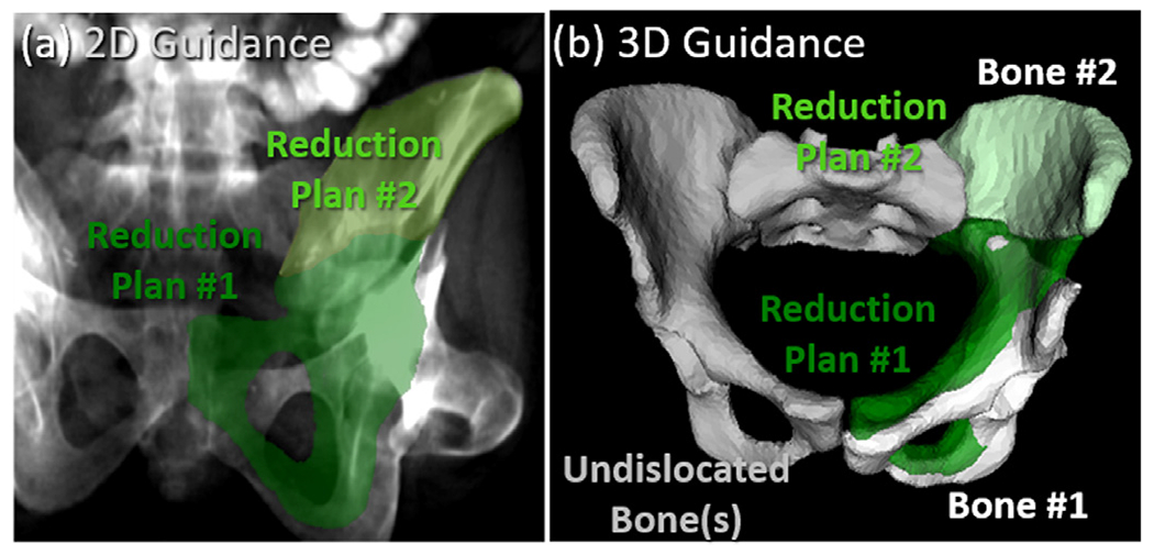
Multi-body 3D-2D registration for guidance of fracture reduction in fluoroscopy illustrated for a unilateral two-body fracture. (a) Illustration of 2D guidance. The preoperative reduction plans for the bone fragments are projected and superimposed (light and dark green) on an AP fluoroscopic image using the 3D-2D registration result to provide 2D guidance. (b) Illustration of 3D guidance. With the unfractured bone labeled in gray, 3D renderings of bone fragments solved by 3D-2D registration of preoperative segmentations to intraoperative fluoroscopy are shown as white surfaces. The reduction plans are overlaid (green) to provide 3D guidance of further reduction.
4. Experimental methods
4.1. Simulation study: Fracture reduction planning
The preoperative fracture reduction planning method (Section 3.2) was evaluated in a simulation study involving a leave-one-out cross validation of the atlas (N = 40). For each atlas member, the corresponding CT image and ground truth pelvic bone segmentations were used to simulate random pelvic fracture patterns, while the rest of the atlas was used for adaptive template construction. Extending from dislocation-only simulations (Han et al., 2020a) and iliac wing fracture simulations (Han et al., 2020b), the current study simultaneously simulates fractures and dislocations in a randomized fashion. Three categories of pelvic fractures were simulated: (1) unilateral two-body fractures [Fig. 3(a)]; (2) unilateral three-body fractures [Fig. 3(b)]; and (3) bilateral two-body fractures [Fig. 3(c)]. The unilateral fractures involved fractures and dislocations of one side of the pelvis (either left or right innominate bone), and the bilateral fractures involved fractures and dislocations of both sides of the pelvis (both left and right innominate bones). Disruptions of the sacrum were not simulated in the current study (and are relatively rare (Rodrigues-Pinto et al., 2017)). In total, 120 cases were simulated (3 fracture categories for each of the 40 atlas members).
Fig. 3.
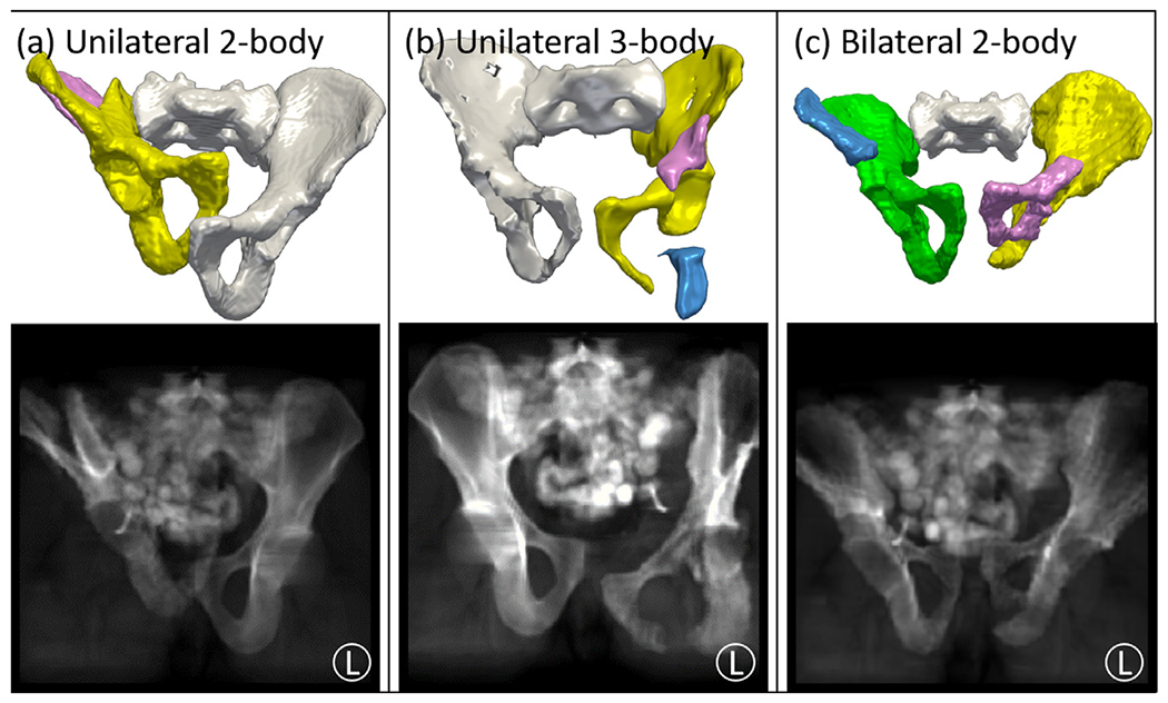
Simulation study for fracture reduction planning and fluoroscopy-guided navigation. Three categories of fracture were simulated as illustrated in top example volume renderings and projection views: (a) unilateral 2-body fractures; (b) unilateral 3-body fractures; and (c) bilateral 2-body fractures. The row shows 3D rendering of simulated fractures, with unfractured bone fragments in white and fracture-dislocated bone fragments in various colors. The bottom row shows simulated AP fluoroscopic images of the corresponding pelvic fracture.
For each simulation case, following the fracture simulation method in (Abdi et al., 2019), the innominate bone was dissected by a cuboid (B) with an arbitrary size and orientation to yield multiple fracture fragments. Compared to more intuitively dissecting using a plane, the cuboid method adds more degrees of freedom and creates more complex fracture patterns. Taking a unilateral (left-side) two-body fracture case as an example, the left innominate bone Ileft was dissected by a random cuboid to form two bone fragments Ileft ∘ B and Ileft ∘ B′, where B′ is the complement of the binary cuboid, and A ∘ B is the element-wise matrix product. Various dislocations Td were further imparted to the bone fragments with magnitude uniformly distributed from 0-20 mm and 0°-15°. Dislocations that resulted in collision between bones were removed. Soft-tissue gaps between bones following transformation were filled with inpainting via linear interpolation.
Segmentation of bone fragments was performed using CMF with one “seed point” for smaller fragments and up to three “seed points” for larger fragments. As a comparison, the multi-step segmentation method in (Fornaro et al., 2010) was implemented using adaptive thresholding of cortical bone, adaptive region-growing of trabecular bone from cortical bone, and a graph-cut bone fragment segmentation based on one “seed point” from each fragment. The same parameters were used as described in (Fornaro et al., 2010). The method is denoted as “multi-step region-grow”. The same parameters were used as described in (Fornaro et al., 2010). The accuracy of segmentation was quantified in terms of the Dice coefficient (DC) between the segmentation and the ground truth segmentation, as well as Hausdorff distance (HD) of the segmentation contours to ground truth. The methods were evaluated to quantify the sensitivity to “seed point” selection, with success rate defined by the ratio of trials with DC > 0.70 for all bone fragments.
An alternative fracture reduction planning method was implemented specifically to test the assumption of pelvic bilateral symmetry. A symmetry plane defined by the sacral midline was determined from the sacrum segmentation, and the unfractured contralateral side was mirrored about the symmetry plane to serve as a fixed image for multi-body registration. The registration (referred to below as the “mirror” method) was performed with the following cost function:
| (10) |
where Imirror is the image obtained from contralateral mirroring. The accuracy of the fracture reduction planning was quantified in terms of the difference between the simulated dislocation and the bone fragment transformations from the multi-body registration in Eq. (8): . The fracture reduction error was analyzed in terms of constituent translational and rotational magnitudes, which carry useful physical meaning that is more informative to the surgeons for quantitative understanding of planning error margins.
4.2. Simulation study: Fluoroscopy-guided navigation
To quantify the accuracy of multi-body 3D-2D registration and fluoroscopy-guided navigation, intraoperative fracture reduction scenes were simulated from the CT images of pelvic fracture in Section 4.1, as shown in the top row of Fig. 3. Random intermediate reductions Tr were imparted to the dislocated bone fragments to emulate an intermediate surgical stage during fracture reduction, such that . Soft-tissue gaps resulting from bone transformation were inpainted via linear interpolation. As shown in the bottom row of Fig. 3, the corresponding fluoroscopic images were simulated via forward projection using the projection geometry of a mobile C-arm (source-axis distance=600 mm, source-detector distance=1100 mm). The segmentations of bone fragments were registered to two fluoroscopic images of standard pelvic views (AP, inlet, or oblique) using multi-body 3D-2D registration.
The 3D-2D registration was performed in the unilateral two-body and three-body fracture simulations, and a total of 80 registrations were performed (two fracture categories, one for each of the 40 atlas members). The registration was initialized by the poses from preoperative CT and typical x-ray system geometry. The registration accuracy was measured in terms of the difference between the intermediate reduction and the registration solution of each bone fragment: , from which the translational and rotational components were extracted. The translational and rotational errors were decomposed into in-plane (parallel to the detector plane) and out-of-plane components.
4.3. Proof of concept study: A cadaver experiment
The performance of the proposed method for reduction planning and fluoroscopy-guided navigation was evaluated in a fresh human cadaver study designed to follow common clinical workflow for fluoroscopic guidance of fracture fixation. The specimen was acquired from the Maryland Anatomy Board and used under approved state and institutional protocols. A fellowship-trained orthopaedic surgeon created a fracture of the left innominate bone to mimic a common Tile C1 fracture, resulting in three bone fragments and no dislocation of the SI joint or PS. A pre-operative MDCT was acquired (Precision CT, Canon Medical Systems, Tustin CA) and reconstructed at 0.39x0.39x0.5 mm3 voxel size. Bone fragment segmentation and fracture reduction planning was computed based on pre-operative CT.
The utility of fluoroscopy-guided navigation was evaluated with the surgeon performing fracture reduction on the cadaver with and without guidance from the preoperative planning. Fig. 4(a) shows the experimental setup, with the reduction surgery guided by fluoroscopy acquired on a mobile C-Arm (Cios Spin, Siemens Healthineers, Erlangen, Germany). An in-house intraoperative guidance system was built using 3D Slicer and TREK framework (Uneri et al., 2012). The guidance system displayed both 2D and 3D navigation as shown in Fig. 4(b). The surgeon was first surveyed on general challenges in fracture reduction, fluoroscopy acquisition, and change of surgical difficulty with respect to experience. The surgeon was further asked to rate the usability of the guidance system before and after the procedure for both 2D navigation and 3D navigation. Furthermore, the surgeon was asked to comment on the potential to reduce exposure time associated with “fluoro hunting” (i.e., searching for a particular fluoroscopic view that best depicts the anatomy and instrumentation) and how the utility of the system could vary between novice and expert surgeons. The workflow associated with the proposed method was primarily evaluated in terms of computation time in each step, since no additional devices or imaging was needed.
Fig. 4.

Cadaver study for fracture reduction planning and fluoroscopy-guided navigation. (a) Experimental setup, showing the mobile C-Arm, cadaver, and navigation interface. (b) Detailed view of the navigation screen, with both 2D navigation (fluoroscopic images overlaid with the preoperative plan) and 3D navigation (slice and 3D renderings of the preoperative plan and current bone poses relative to preoperative CT).
In addition to the qualitative usability assessment, the accuracy of the system was also quantitatively evaluated. A MDCT scan was acquired before fracture as a ground truth for fracture reduction planning, and the residual transformation between the ground truth bone pose and planning bone pose was computed. In terms of segmentation, bone fragments were manually segmented, and the Dice Coefficient of the semi-automatic segmentation was computed. Since the same surgeon created the fracture and performed surgical reduction, a potential bias toward a very accurate final reduction could be present. For this reason, the accuracy of the postoperative final reduction with/without guidance was not evaluated relative to ground truth; rather, only the accuracy of the intraoperative guidance system was evaluated, which is independent of the surgeon’s familiarity with the fracture. Intraoperatively, bone fragments were manipulated to 3 different stages during fracture reduction surgery, and 6 fluoroscopic images with different C-Arm poses that resembles common views in orthopaedic surgery (e.g. PA, LAT, and Inlet) were acquired at each stage. A cone-beam CT (CBCT) scan was also acquired on the C-Arm at each stage for ground truth definition of 3D bone poses. 3D-2D registration was computed using any combination of two fluoroscopic images, and the accuracy was quantified by the transformation difference between the registration solution and the ground truth poses from CBCT.
4.4. Retrospective clinical feasibility study
The proposed method was further quantitatively assessed in an IRB-approved retrospective study of three patients undergoing pelvic fracture reduction surgery. The three patients were selected to represent different categories of pelvic fractures: two cases demonstrating different types of common pelvic ring fractures, and the third case presenting fracture of acetabulum and articular surface.
The first patient experienced a high-energy impact to the left side, resulting in unilateral dislocation of the left innominate bone, disruptions of both the left sacroiliac (SI) joint and the pubic symphysis (PS), and a three-body fracture of the left iliac crest. The second patient experienced a high-energy impact anteriorly, resulting in bilateral trauma, featuring dislocation of the right innominate bone, disruptions of both the right SI joint and PS, and comminuted fractures of the pubic rami on both sides. Small bone fragments about the left pubic ramus fracture were identified (but were not surgically reduced – instead, left in place for natural bone healing); therefore, the small bone fragments were not considered in the fracture reduction planning framework. The third patient exhibited a two-body right acetabular fracture resulting from trauma of the right femur. The acetabular fracture in Case 3 is clinically more challenging than pelvic ring fractures in Cases 1-2 due to its articulation with the femoral head. Unlike pelvic ring reductions (for which up to 5-10 mm residual displacement may be acceptable (Halawi, 2016; Smith et al., 2005)), acetabulum reduction requires residual displacement within 2 mm for proper functional outcomes (Halvorson et al., 2014).
For each case, preoperative CT was acquired (Somatom Definition Flash, Siemens Healthineers, Erlangen Germany) and reconstructed at 0.74×0.74×3 mm3 voxel size and 512×512×260 voxels. Semi-automatic segmentation of bone fragments via continuous max-flow was computed, and the accuracy of the segmentation was quantified by Dice Coefficient and Hausdorff Distance to manual segmentation by a research assistant trained in pelvic anatomy. The manual segmentation was performed in The Medical Imaging Toolkit (Wolf et al., 2005) with voxel-level annotation, linear intraslice interpolation and manual correction. The proposed fracture reduction planning framework was applied to estimate transformations of bone fragments to obtain proper reduction. In comparison, manual definition of fracture reduction planning was conducted by a fellowship-trained, orthopaedic surgeon with over ten years of experience. The surgeon manually manipulated the poses of 3D segmentation models on a 3D workstation, and the difference between the automatic and manual plans was quantified in terms of the magnitude of rigid transformation between each fragment in the two plans.
Two intraoperative and two postoperative fluoroscopic images (AP and inlet views) were also acquired in each case using a mobile radiography system (DRX Revolution, Carestream Health, Rochester NY) to visualize pelvic anatomy before and after reduction. Unlike the simulation study in Section 4.2 that used two fluoroscopic images for 3D-2D registration, each fluoroscopic image was individually registered due to patient motion between the fluoroscopy acquisitions. Since neither intraoperative nor postoperative CT were available for these cases, ground truth definition of 3D poses could not be obtained, and the accuracy of 3D-2D registration could not be evaluated in terms of 3D transformation differences. Instead, the accuracy was quantified by 2D projection distance error (PDE) – i.e., the distance between registered 3D anatomical landmarks projected onto the detector plane and the corresponding landmarks identified on the fluoroscopic image. Eight to thirteen anatomical landmarks were manually annotated depending on the field of view of the fluoroscopic images.
5. Results
5.1. Simulation: Fracture reduction planning
The performance of bone fragment segmentation among 120 simulations was first evaluated. The multi-step region-grow method (Fornaro et al., 2010) and the CMF method achieved success rates (fraction of cases with DC > 0.70 for all bone fragments) of 91% and 96%, respectively. The CMF method showed slightly less sensitivity to “seed point” placement. DC was comparable between the two methods (0.90 ± 0.07 and 0.92 ± 0.06, respectively) with no statistical significance observed via paired student t-test. However, the multi-step region-grow method showed higher HD (4.1 ± 2.0 mm) compared to the CMF method (2.7 ± 1.7 mm, p ⪡ 0.01). As HD quantifies the alignment of the segmentation contour, the difference in performance was observed primarily around narrow joint spaces and trabecular bone edges, were the multi-step region-grow method often showed over-segmentation. The multi-label approach in the CMF method, along with distance to “seed points” and a prior bone intensity distribution, successfully avoided such effects.
The performance of fracture reduction planning was evaluated in the unilateral 2-body fracture simulation by comparing the mirror method and the proposed adaptive template method. As summarized in Table 2 and plotted in Fig. 5(a–b), the mirror method exhibited translational errors of 5 .3 ± 3.7 mm and rotational errors of 7.4 ± 4.3°. One source of error lies in the assumption of contralateral symmetry (e.g., pelvic asymmetry associated with the dominant leg or other normal anatomical variations resulting in shape differences between the left and right ilium). Fig. 5(c) exemplifies such error, where the mirrored bones resulted in a solution that compresses the pubic symphysis and dislocates the left SI joint. In addition, the shape difference between the left and right iliac crests (more elongated in the superior-inferior direction on the right side) resulted in residual error of the iliac crest fragment (in pink) and a gap between the two bone fragments.
Table 2.
Reduction accuracy of the three fracture categories comparing the “mirror” and “adaptive” methods.
| Fracture Category | Reduction Error: Translation (mm) / Rotation (°) |
|||
|---|---|---|---|---|
| Mirror | Adaptive | |||
| Unilateral 2-Body | 5.3 ± 3.7 mm | 7.4 ± 4.3°. | 2.2 ± 1.6 mm | 2.2 ± 1.6° |
| Unilateral 3-Body | 6.2 ± 4.4 mm | 9.5 ± 5.7° | 2.6 ± 1.6 mm | 3.7 ± 1.8° |
| Bilateral 2-Body | N/A | N/A | 2.8 ± 1.5 mm | 3.3 ± 2.1° |
Fig. 5.

Fracture reduction planning for a unilateral 2-body fracture simulation: comparison of the mirror and adaptive template methods. (a) Translational error and (b) rotational error. Boxplots are superimposed with the distribution of 80 sample points (two fragments each of 40 simulations). Clinical acceptance range (5 mm and 5°) are plotted in red dashed lines. (c) and (d) show example 3D renderings of the pelvis after reduction planning using the mirror and adaptive methods, respectively. In each case, the unfractured bone is labeled white, and fractured-dislocated bone fragments are yellow and pink. Red circles highlight important differences between the two methods at the PS and fracture plane.
The proposed adaptive template method achieved translational error of 2.2 ± 1.5 mm and rotational error of 2.2 ± 1.5°, which are both significantly smaller than the mirror method (p ⪡ 0.01 using paired student t-test). The errors were further decomposed into 3 translational directions (1.3 ± 1.2 mm, 1.4 ± 1.2 mm, 1.3 ± 1.2mm and 3 rotational directions (1.4 ± 1.2°, 1.2 ± 1.2°, 1.5 ± 1.3°). The error in each direction was found to be equally distributed and thus not reported in subsequent sections. Comparing to the reduction result using mirror method in Fig. 5(c), the result using adaptive template in Fig. 5(d) shows several improvements as indicated by the red circles, including a better aligned pubic symphysis and a narrower gap between the two bone fragments. By accounting for statistical variations in bone shapes and poses via the SSM and SPM, the adaptive template method significantly improves the quality of the target shape used for registration and thus improves the overall reduction planning accuracy.
The methods were further evaluated in a simulation study of unilateral three-body fractures to examine generalizability to more complex fracture patterns with multiple bone fragments. Fig. 6(a–b) shows the accuracy of fracture reduction planning of unilateral three-body fractures in comparison to two-body fractures. As summarized in Table 2, the mirror method yielded 6.2 ± 4.4 mm and 9.5 ± 5.7° translational and rotational error, respectively. The proposed adaptive method demonstrated significant improvement (p ⪡ 0.01 using paired student t-test), achieving 2.6 ± 1.6 mm and 3.7 ± 1.8°, respectively. The mirror method example in Fig. 6(c) yields a result with dislocation of the PS and misaligned posterior column – each of which is improved with the adaptive method in Fig. 6(d) as highlighted by the red circles.
Fig. 6.

Fracture reduction planning for unilateral three-body fracture simulations, comparing the mirror and adaptive template methods. (a) Translational error and (b) rotational error. Boxplots are superimposed with the distribution of 80 sample points (two fragments each of 40 simulations) for 2-body fractures and 120 sample points (three fragments each of 40 simulations) for 3-body fractures. Clinical acceptance range (5 mm and 5°) are plotted in red dashed lines. (c) and (d) show example 3D renderings of the pelvis after reduction planning. In each case, the unfractured bone is labeled white, and fractured-dislocated bone fragments are yellow, pink, and blue.Red circles highlight important differences between the two methods at the PS and posterior column fracture plane.
Comparing the two-body and three-body fracture cases solved using the adaptive method, a slight decrease in accuracy was observed for the latter (average difference 0.4 mm (not statistically significant) and 1.5“ (p ⪡ 0.01)). As the number of fragments increases, the amount of information associated with the remaining innominate bone is reduced, challenging the SSM adaptation steps and deteriorating the accuracy of the template. Another source of error for a greater number of fragments is the increased dimensionality of the optimization space. Despite these effects, fracture reduction accuracy was within the targeted range of 5 mm and 5° for the strong majority of both two-body (88%) and three-body (77.5%) fracture simulations.
The performance of the adaptive method in bilateral fractures was further examined (for which the mirror method is not applicable). The adaptive method applied to bilateral two-body fractures achieved translational error of 2.8 ± 1.5 mm and rotational error of 3.3 ± 2.1°. As shown in Fig. 7(a–b), the bilateral simulations resulted in slightly higher error in both translation (not statistically significant) and rotation (p = 0.05, computed via unpaired t-test) compared to the unilateral cases, due to challenges in estimating poses of both innominate bones in the SPM adaptation steps. The mean error of the proposed method was within clinically acceptable accuracy (<5 mm and <5°) in the more challenging bilateral fracture cases, adding utility and feasibility to the translation to orthopaedic surgical applications.
Fig. 7.

Fracture reduction planning for bilateral two-body fracture simulations using the adaptive template method. (a) Translational error and (b) rotational error. Boxplots are superimposed with the distribution of 80 sample points (two fragments each of 40 simulations) for unilateral fractures and 160 sample points (four fragments each of 40 simulations) for bilateral fractures.Clinical acceptance range (5 mm and 5°) are plotted in red dashed lines. (c) Example 3D rendering of the pelvis after reduction planning, with unfractured bone fragments in white and fracture-dislocated bone fragments in yellow, pink, blue and green.
5.2. Simulation: Fluoroscopy-guided navigation
The multi-body 3D-2D registration method for fluoroscopy-guided navigation was evaluated in both two-body and three-body unilateral fracture simulations. Fig. 8(a–c) shows example result from a unilateral two-body fracture simulation. As shown in Fig. 8(a), an AP fluoroscopic image of the pelvis is overlaid with DRR Canny edges of each bone fragment after registration. All bone fragments were correctly aligned to the anatomy on the fluoroscopic image, demonstrating accurate 3D-2D registration. Example 2D guidance using 3D-2D registration is shown in Fig. 8(b), in which the reduction plan of the two fracture-dislocated fragments are projected and highlighted on the radiograph to augment fluoroscopy with additional guidance information. By comparing the poses of the registered bone fragments and desired reduction in one or multiple views, further reduction required to restore morphology can be obtained. In addition, Fig. 8(c) shows the corresponding 3D guidance, where bone fragments are rendered at their registered intraoperative poses (unfractured bone fragments in white and fracture-dislocated bone fragments in yellow and pink). The reduction plan is superimposed in green, providing guidance of additional reduction both qualitatively and quantitatively comparable to conventional surgical navigation system.
Fig. 8.

Evaluation of fluoroscopy-guided navigation via multi-body 3D-2D registration, showing the results for an example unilateral two-body fracture simulation. (a) AP fluoroscopic image overlaid with Canny edges of registered bone fragments. (b) Reduction plans of the fracture-dislocated bone fragments highlighted in corresponding colors on the fluoroscopic image. (c) 3D rendering of the reduction plan (green) and the registered bone fragments (unfractured bone fragments in white and fracture-dislocated bone fragments in yellow and pink). 3D-2D registration errors [(d) translational and (e) rotational] characterized in terms of in-plane and out-of-plane directions and comparing results obtained for unilateral two-body and three-body fractures.
As shown in Fig. 8(d), the 3D-2D registration achieved 1.4 ± 0.8 mm and 1.4 ± 0.8 mm in-plane translational error for the two-body and three-body fractures, respectively, while achieving 1.3 ± 0.8 mm and 1.6 ± 1.1 mm out-of-plane error. No statistical significance was found between the two-body and three-body translational errors in either in-plane or out-of-plane directions. The overall translational error combining in-plane and out-of-plane directions was 2.1 ± 0.9 mm and 2.4 ± 1.0 mm for two-body and three-body, respectively, which is within the clinical acceptance error of 5 mm for pelvic ring cases. For acetabular cases with clinical acceptance error of 2mm, the proposed method succeeded in 80% of cases. Rotational errors shown in Fig. 8(e) show 0.1 ± 0.1° in-plane rotational error for the two-body fractures and 0.2 ± 0.1° in the three-body fractures (p ⪡ 0.01 using unpaired student t-test). The same trend was observed in the out-of-plane rotational error, with 0.2 ± 0.1° and 0.3 ± 0.2°, respectively (p ⪡ 0.01 using unpaired t-test). The overall rotational error combining in-plane and out-of-plane directions was 0.3 ± 0.1° and 0.4 ± 0.2° for two-body and three-body fracture, respectively. The slight increase in error is primarily due to the registration of small bone fragments that increase in number with more complex fractures. The 3D-2D registration demonstrated accurate and robust performance over a wide range of simulation cases of different fracture patterns and dislocations despite the presence of potentially confounding image features (e.g., contrast-enhanced bowel).
The overall accuracy of the proposed registration framework depends on the accuracy of reduction planning and 3D-2D registration, which are independent of each other and can happen in arbitrary directions depending on the fracture patterns and image content. The unilateral two-body fracture simulation, for example, achieved mean translational accuracy of 2.6 mm for reduction planning and 2.1 mm for 3D-2D registration. Thus, the overall mean accuracy combining the two would range between the addition and the subtraction of the two errors, 0.5 mm~4.7 mm, which is within the clinical acceptance range of 5 mm suggested in (Shillito et al., 2014; Smith et al., 2005).
5.3. Proof of concept study: A cadaver experiment
As shown in Fig. 9(a), a Tile C1 pelvic ring fracture was imparted to the cadaver’s left innominate bone, resulting in three fragments and intact SI joint and PS. Only one fragment (yellow) not connected by SI joint or PS was isolated and dislocated. Continuous max-flow segmentation achieved overall Dice Coefficient of 0.92 ± 0.04 and HD of 5.2 ± 2.0 mm. While HD was higher due to significant bone spurs associated with osteoarthritis and low bone density, the Dice Coefficient was comparable to the simulation study, and downstream algorithm performance was not affected. Fracture reduction planning using the adaptive method is shown in Fig. 9(b) in green, with the ground truth (defined from pre-fracture CT) overlaid in dark gray. The difference between the automatic plan and ground truth was 2.68 mm and 4.10°, which was deemed clinically insignificant by the surgeon and was within the target accuracy (5 mm) for pelvic ring fracture (Shillito et al., 2014; Smith et al., 2005).
Fig. 9.

Fracture reduction planning and fluoroscopy-guided navigation in cadaver study. (a) 3D rendering of the preoperative CT image segmentation using continuous max-flow, showing fracture and dislocation of the left innominatebone. (b) 3D rendering of the pelvis after reduction planning using the adaptive method. Surgeon’s manual definition is overlaid in gray. (c) Example AP intraoperative fluoroscopic image. (d) The AP fluoroscopic image overlaid with DRR Canny edges of registered bone fragments in corresponding colors. (e) Preoperative reduction plan highlighted on the fluoroscopic image in green.
The performance of 3D-2D registration was further evaluated on multiple sets of two-view fluoroscopic images. An example AP intraoperative fluoroscopic image is shown in Fig. 9(c) and the corresponding registration is shown in Fig. 9(d), with DRR Canny edges of the dislocated fragment and the nondislocated fragments overlaid in yellow and blue, respectively. Alignment of the DRR edges to anatomy evident in the fluoroscopic image was obtained, and the registration error was 1.5 ± 0.6 mm in-plane, 1.8 ± 0.5 mm out-of-plane translational error and 0.6 ± 0.2° in-plane, 0.7 ± 0.4° out-of-plane rotational error in a total of 16 registration trials. The 3D-2D registration performance was comparable to the simulation study in Section 5.2. In Fig. 9(e), the fracture reduction plan is overlaid on the fluoroscopic image in green to illustrate the desired pose to restore the left innominate bone.
The usability of the planning and guidance system was evaluated in the cadaver study. The surgeon was surveyed before and after using the system for fracture reduction and the detailed questionnaire is shown in Appendix I. The surgeon reported that experienced trauma surgeons should be fairly confident in performing reduction using unlabeled fluoroscopic images but anticipated that less experienced surgeons attempting to perform the reduction using unlabeled fluoroscopic images would find the task considerably challenging. The surgeon indicated that major challenges lie in comminuted fractures and multi-body fractures, both of which are addressed in the proposed system. Another challenge in conventional workflow is to acquire specific fluoroscopic views to visualize bone fragments, requiring repeated exposures (“fluoro hunting”).
Two modes of guidance were presented to the surgeon as shown in Fig. 4(b). The first mode of guidance was 2D guidance alone, which augments fluoroscopy with projected preoperative planning. The surgeon commented that the system was very useful in the reduction procedure and would allow fewer fluoroscopy acquisition. In addition, the 2D guidance was very intuitive and in a format familiar to orthopaedic surgeons, which would improve surgical capability without adding additional cognitive load, especially for less experienced surgeons. The second mode of guidance combined 2D and 3D guidance, which additionally shows triplanar views and 3D rendering of registered bone fragments with respect to preoperative plans. The surgeon commented that the 2D+3D guidance system was somewhat useful to the reduction surgery. Since 2D fluoroscopy is still the mainstream in orthopaedic trauma surgery, the 3D interface is new to the surgeons and would require a learning curve. Nevertheless, the 3D guidance provided multidimensional understanding of reduction accuracy compared to 2D guidance and would alleviate challenges of “fluoro hunting,” since any two fluoroscopic views (with structures of interest in the field of view) are sufficient for registration and 2D+3D guidance.
The workflow associated with the proposed system was also evaluated. No additional imaging or devices was required, as the system only used images already acquired in clinical workflow. Therefore, computation time was the primary concern for integration of the system to clinical workflow. Table 3 summarizes computation time for each step of the preoperative and intraoperative steps. Preoperatively, runtime for segmentation including seed points input and continuous max-flow was ~4.5 min, and runtime for fracture reduction planning was ~42 min. The main bottleneck in the relatively long runtime of fracture reduction planning was the memory-intensive, evolution-based CMA-ES optimization on 3D images, which requires evaluation on multiple instances per iteration. Besides the seed points input step, all other steps were fully automated. The preoperative steps can be conducted prior to the case, and therefore do not bear on intraoperative workflow. Intraoperative runtime includes multi-body 3D-2D registration and 2D / 3D guidance, with overall runtime ~2 min for the first fluoroscopic image acquired in the procedure. For subsequent registrations with better initialization, runtime can be further reduced due to improved initialization. In fluoroscopy-guided orthopaedic surgery, surgeons often rely on step-and-shoot workflow in which a single fluoroscopic image is acquired to assess the surgical field before acquiring a subsequent view, thus fitting with the runtime of the proposed framework. The reported runtime is based on a basic research implementation, and further optimization and acceleration is discussed in the Discussion to bring runtime more suitable for the workflow requirement. The surgeon commented that the additional runtime associated with the guidance system was acceptable considering the benefit gained from improved surgical guidance, improved understanding of reduction accuracy, and reduced dependence on fluoro hunting to acquire specific fluoroscopic views.
Table 3.
Computation time of the preoperative and intraoperative framework
| PREOPERATIVE RUNTIME(MEAN±STH) (MIN) | INTRAOPERATIVE RUNTIME(MEAN±STD) (S) | ||
|---|---|---|---|
| SEED POINTS INPUT | 3.3 ± 0.7 | Multi-Body 3D-2D | 120.6 ± |
| CONTINUOUS MAX-FLOW SEGMENTATION | 1.4 ± 0.2 | Registration | 48.0 |
| FRACTURE REDUCTION PLANNING | 42.3 ± 10.9 | 2D/3D Guidance | 0.2 ± 0.1 |
5.4. Retrospective clinical feasibility study
The feasibility of the proposed method was further evaluated in an IRB-approved, retrospective clinical study involving three patients undergoing pelvic fracture reduction surgery at our institution. The three cases presented distinct fracture and dislocation patterns that challenged the registration methodology with increasing levels of complexity and accuracy requirement.
5.4.1. Case 1: Unilateral iliac crest fracture
As shown in the segmented preoperative CT image in Fig. 10(a), Case 1 involves a patient with a comminuted fracture of the left ilium with dislocation of the left SI joint and diastasis of the PS. Three major bone fragments were identified: two iliac crest fragments and the remaining innominate bone. Continuous max-flow segmentation achieved overall DC of 0.87 ± 0.05 and HD of 2.8±0.9. The lower segmentation accuracy compared to the simulation study is attributed to the relatively blurry bony boundaries of the comminuted fracture and multiple tiny fragments around the fracture site. The fracture reduction planning result obtained using the adaptive template method is shown in Fig. 10(b), demonstrating a strong improvement in the alignment of bone morphology at the fracture site, the left SI joint, and the PS. Manual planning by the surgeon is overlaid in dark gray, showing a small superior displacement from the proposed method. The difference between the automatic and manual planning was 3.3 ± 0.3 mm and 2.5 ± 2.1°, which was deemed clinically insignificant by the surgeon (i.e., could not differentiate between the two), and is within the target accuracy (5 mm) for pelvic ring fracture reduction (Shillito et al., 2014; Smith et al., 2005).
Fig. 10.

Fracture reduction planning and fluoroscopy-guided navigation in clinical Case 1. (a) 3D rendering of the preoperative CT image segmentation using continuous max-flow, showing fracture and dislocation of the left innominate bone. (b) 3D rendering of the pelvis after reduction planning using the adaptive method. Surgeon’s manual definition is overlaid in gray. (c) Example AP intraoperative fluoroscopy. (d) The AP fluoroscopic image overlaid with DRR Canny edges of registered bone fragments in corresponding colors. Fluoroscopic image landmarks (green triangle) and 3D projected landmarks (corresponding color squares) are also overlaid. (e) Preoperative reduction plan highlighted on the fluoroscopic image in corresponding colors.
An example AP intraoperative fluoroscopic image is shown in Fig. 10(c) from which multi-body 3D-2D registration was computed. In Fig. 10(d), DRR Canny edges of the three fragments and the other two healthy bones (right innominate and sacrum) are overlaid on the fluoroscopic image using the same colors as used in Fig. 7(a–b), showing reasonable alignment with the anatomy. The registration achieved PDE of 3.0 ± 1.4 mm as shown by the close alignment between the fluoroscopic image anatomical landmarks (green triangles) and 3D projected landmarks (corresponding color squares). The registration converged to the correct solution even when the field of view was limited and bone fragments were partially occluded. In Fig. 10(e), the fracture reduction plan is superimposed on the fluoroscopy with corresponding bone colors to illustrate the desired poses to restore the left innominate bone.
5.4.2. Case 2: Bilateral pubic rami fracture
As shown in Fig. 11(a), Case 2 involves a patient with bilateral trauma resulted from high energy impact from the anterior direction. Bilateral pubic rami were fractured, and the right SI joint was dislocated. In addition, a comminuted fracture was observed around the left inferior pubic ramus, resulting in multiple shattered tiny bone fragments, which were not surgically treated and hence left out in the proposed framework. Continuous max-flow segmentation achieved DC of 0.89 ± 0.04 and HD of 3.8 ± 1.2 mm. Fig. 11(b) shows the result from the fracture reduction planning with much better restored morphology. It is worth to note that the healthy bony morphology was maintained in the left inferior pubic ramus, where a gap was automatically kept for the tiny bone fragments not surgical treated. Due to the nature of complex pelvic shape and the complete reference from the adaptive template, no explicit modeling of missing fragments was needed. Such scenario would cause challenges in methods using fracture line matching as in (Willis et al., 2007; Zhou et al., 2009). The surgeon’s manual plan is superimposed in dark gray, showing close alignment with the proposed method. The difference between the two plans was 2.6 ± 0.3 mm, 3.4 ± 1.8° and was deemed clinically insignificant by the surgeon. Case 1 and 2 were both considered as pelvic ring fractures, and the proposed reduction planning yielded accuracy within the 5 mm clinical acceptance range.
Fig. 11.

Fracture reduction planning and fluoroscopy-guided navigation in Case 2. (a) 3D rendering of the preoperative CT image segmentation using continuous max-flow, showing fracture-dislocation of the bilateral pubic rami. (b) 3D rendering of the pelvis after reduction planning using the adaptive method. Surgeon’s manual definition is overlaid in gray. (c) Example AP intraoperative fluoroscopic image. (d) The AP fluoroscopic image overlaid with DRR Canny edges of registered bone fragments in corresponding colors. Fluoroscopic image landmarks (green triangle) and 3D projected landmarks (corresponding color squares) are also overlaid. (e) Preoperative reduction plan highlighted on the fluoroscopic image in corresponding colors.
Example AP intraoperative fluoroscopic image and the 3D-2D registration result are shown in Fig. 11(c–d), respectively. The registration achieved 2.5 ± 1.2 mm PDE, despite the presence of surgical instruments in the fluoroscopic image that were not in the 3D models. Fig. 9(e) shows fluoroscopy-guided navigation that high-lights the reduction plan on the fluoroscopic image in the corresponding color of each bone fragment.
5.4.3. Case 3: Acetabular fracture
As shown in Fig. 12(a), Case 3 involves a patient with a two-body acetabular fracture. A small fragment at the posterior side of the acetabulum was fractured and severely dislocated (over 90°). Continuous max-flow segmentation achieved DC of 0.95 ± 0.02 and HD of 1.6 ± 0.5 mm. Since no overall innominate bone dislocation was present, the adaptive template method did not use SPM, thus bypassing Stage (3) in Table 1.Fig. 12(b) shows the result from the proposed fracture reduction planning, with the dislocation of more than 90° successfully resolved. The difference between the proposed method and the surgeon’s manual plan was quantified to be 1.0 mm and 5.8°, which was larger than the first two cases. Example AP fluoroscopic image, 3D-2D registration, and fluoroscopy-guided navigation results are shown in Fig. 12(c–e), respectively, with PDE 2.2 ± 1.1 mm and performance comparable to the first two cases.
Fig. 12.
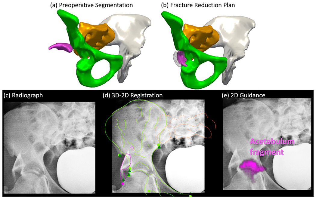
Fracture reduction planning and fluoroscopy-guided navigation in Case 3. (a) 3D rendering of the preoperative CT image segmentation using continuous max-flow, showing fracture and dislocation of the acetabulum. (b) 3D rendering of the pelvis after reduction planning using the adaptive method. Surgeon’s manual definition is overlaid in gray. (c) Example AP intraoperative fluoroscopic image. (d) The AP fluoroscopic image overlaid with DRR Canny edges of registered bone fragments in corresponding colors.Fluoroscopic image landmarks (green triangle) and 3D projected landmarks (corresponding color squares) are also overlaid. (e) Preoperative reduction plan augmented on the fluoroscopic image in corresponding colors.
Comparing to the 5 mm acceptance range for pelvic ring fracture in Case 1 and 2, acetabular fracture reduction requires a higher precision as low as 2 mm (Halvorson et al., 2014) to restore proper hip joint function. Improvement on the method is needed to reduce the reduction error and fit the clinical requirement of acetabular fracture. For example, other than modeling the shape of the full pelvis, a local shape model of the acetabulum can be computed to refine the reduction planning. In addition, a model of the femoral head can be incorporated for more accurate estimation of the overall hip joint shape.
6. Discussion and conclusion
A framework for CT image segmentation of fractured pelvis, fracture reduction planning, and 3D-2D registration for fluoroscopy-guided navigation was reported. The framework involves semi-automatic multi-label segmentation in CT images of fracture pelvis using continuous max-flow, achieving segmentation Dice Coefficient of 0.92 ± 0.06 in the simulation study. For fracture reduction planning, multi-body registration was proposed to register bone segmentations to an adaptive template constructed from SSM and SPM that adapts to patient-specific anatomy. The planning achieved 2-3 mm and 2-3° error for unilateral two-body, three-body, and bilateral two-body fracture simulations. For navigation, the framework solves a multi-body 3D-2D registration to track multiple bone fragments in intraoperative fluoroscopy / radiography, yielding ~2 mm and less than 0.5° registration accuracy in the simulation study. The cadaver study achieved DC of 0.92, reduction planning error of 2.68 mm and 4.1°, and intraoperative guidance error within 1 mm and 1°. The retrospective clinical study of three patient cases demonstrated comparable accuracy to the simulation study, achieving ~0.9 segmentation DC, ~3 mm reduction planning accuracy, and ~2.5 mm 3D-2D registration PDE.
The performance of the pelvic fracture reduction system was shown to improve reduction accuracy without navigation support and is on par with existing reduction navigation systems. In a survey of patients with pelvic ring fracture reduction surgery without navigation, (Borg et al., 2010) reported residual reduction error exceeding 5 mm in 17% of patients undergoing posterior ring reduction surgery, 29% of patients undergoing pubic rami reduction, and 52% of patients undergoing pubic symphysis reduction. The proposed system shows more consistent performance, with only 12% - 25% of cases presenting greater than 5 mm error for a variety of fracture patterns. In terms of reduction with navigation, (Dagnino et al., 2016) presented a lower limb reduction navigation system using manual reduction planning and optical tracking, showing reduction error of ~ 1mm and 1°. For a more complicated pelvic fracture scenario, (Zhao et al., 2018) presented a computer-aided pelvic fracture reduction system using manual planning and intra-operative CT for guidance that yielded an overall mean reduction error of 3.2 mm and 2.7°. The proposed fluoroscopy-guided navigation system in this work shows comparable reduction accuracy without additional requirements (e.g., optical tracking devices, attaching rigid-body markers on bones, or intraoperative CT).
The segmentation accuracy of bone fragments affects the accuracy of downstream computations, including both fracture reduction planning and fluoroscopy-guided navigation. As reported in Section 5.3, the continuous max-flow segmentation was susceptible to errors in areas of comminuted fractures, where bone boundaries were less defined and bone fragments were partially connected. This error was somewhat mitigated in the current work using a “soft regularization” of collision constraints in Eq. (8), which allowed partial overlap between bone fragments to still be an acceptable solution as long as the reduction overall matched with the adaptive template. In addition, the segmentation method is semi-automatic, requiring some manual interaction of input seed points. To improve segmentation accuracy and achieve full automation, more sophisticated deep learning algorithms will be considered, such as supervised U-Net segmentation using more simulation and clinical datasets of pelvic fractures (Kayalibay et al., 2017; Ronneberger et al., 2015) and unsupervised segmentation based on local center of mass of each bone fragment (Aganj et al., 2018).
The clinical feasibility study verified the applicability of the method to real clinical data but is not without its limitations. While the cases presented a range of common pelvic fracture patterns and included multiple image instances (multiple fluoroscopic images) that was sufficient to demonstrate basic feasibility, the study was retrospective and involved just three subjects; therefore, the generalizability of the method to the wide range of possible pelvic fracture scenarios is subject to future evaluation. The study permitted visual assessment of registration performance and quantitative evaluation of 2D PDE, but 3D evaluation of intraoperative navigation accuracy would be preferable, drawing on intraoperative CT or cone-beam CT that may be available in future clinical studies. In addition, evaluating the accuracy of surgical reduction by comparing intraoperative registration results to postoperative CT would add value to the study. Of course, confirmation that improvements in reduction accuracy gained by this approach are associated with improved functional outcome is the subject of longer-term clinical research.
The preoperative process for fracture reduction planning exhibited a runtime of ~45 min, and runtime acceleration is certainly desirable even for preoperative workflow. For example, ongoing work considers tetrahedral volumetric mesh representations of bone fragments, which is more compact and numerically efficient for volume transformations without the need of interpolation at every iteration. In addition, practical implementation of fluoroscopy-guided navigation in the intraoperative workflow could also benefit from further acceleration, for example, by adopting a cascade of optimizers in 3D-2D registration using slower but more robust CMA-ES at coarse resolutions and a faster, derivative-based optimizer at finer resolutions (Grupp et al., 2019).
The multi-body registration framework demonstrated accurate performance in a variety of simulation and clinical scenarios for fracture reduction planning and fluoroscopy-guided navigation in pelvic trauma surgery. The solution offers the potential for application in mainstream trauma surgery since it uses images already routinely acquired in common clinical workflow, does not introduce additional hardware or tracking systems, and requires minimal user interaction. The system has the potential to improve surgical accuracy, reduce radiation dose associated with trial-and-error “fluoro hunting,” and provide quantitative analysis of the surgical product compared to the reduction plan. Incorporating the work reported here for multi-body fracture reduction with previously reported methods for automatic pelvic fixation planning (Han et al., 2019) and guidance of pelvic dislocations (Han et al., 2020a), a fairly comprehensive system for pelvic trauma guidance can be envisioned that could help address the need for improved accuracy and reduced radiation dose in pelvic trauma surgery.
Supplementary Material
Acknowledgement
This research was supported by NIH grant R01-EB-017226 and academic-industry partnership with Siemens Healthineers (Forcheim, Germany).
Footnotes
Declaration of Competing Interest
The authors declare that they have no known competing financial interests or personal relationships that could have appeared to influence the work reported in this paper.
Supplementary materials
Supplementary material associated with this article can be found, in the online version, at doi:10.1016/j.media.2020.101917.
References
- Abdi AH, Pesteie M, Prisman E, Abolmaesumi P, Fels S, 2019. Variational shape completion for virtual planning of jaw reconstructive surgery. In: Lecture Notes in Computer Science (Including Subseries Lecture Notes in Artificial Intelligence and Lecture Notes in Bioinformatics). Springer, pp. 227–235. [Google Scholar]
- Aganj I, Harisinghani MG, Weissleder R, Fischl B, 2018. Unsupervised medical image segmentation based on the local center of mass. Sci. Rep 8, 1–8. 10.1038/s41598-018-31333-5. [DOI] [PMC free article] [PubMed] [Google Scholar]
- Albrecht T, Lüthi M, Gerig T, Vetter T, 2013. Posterior shape models. Med. Image Anal 17, 959–973. 10.1016/j.media.2013.05.010. [DOI] [PubMed] [Google Scholar]
- Albrecht T, Vetter T, 2012. Automatic fracture reduction. In: Lecture Notes in Computer Science (Including Subseries Lecture Notes in Artificial Intelligence and Lecture Notes in Bioinformatics), pp. 22–29. [Google Scholar]
- Balestra S, Schumann S, Heverhagen J, Nolte L, Zheng G, 2014. Articulated statistical shape model-based 2D-3D reconstruction of a hip joint. In: Lecture Notes in Computer Science (Including Subseries Lecture Notes in Artificial Intelligence and Lecture Notes in Bioinformatics). Springer Verlag, pp. 128–137. [Google Scholar]
- Borg T, Berg P, Fugl-Meyer K, Larsson S, 2010. Health-related quality of life and life satisfaction in patients following surgically treated pelvic ring fractures. A prospective observational study with two years follow-up. Injury 41, 400–404. 10.1016/j.injury.2009.11.006. [DOI] [PubMed] [Google Scholar]
- Bossa MN, Olmos S, 2006. Statistical Model of Similarity Transformations: Building a Multi-Object Pose. In: 2006 Conference on Computer Vision and Pattern Recognition Workshop (CVPRW’06), p. 59. [Google Scholar]
- Byrd RH, Jean •, Gilbert C, Nocedal J, 2000. Digital Object Identifier (DOI) 10.1007/s101070000189. Math. Program., Ser. A 89, 149–185. 10.1007/s101070000189. [DOI] [Google Scholar]
- Cimerman M, Kristan A, 2007. Preoperative planning in pelvic and acetabular surgery: The value of advanced computerised planning modules. Injury 38, 442–449. 10.1016/j.injury.2007.01.033. [DOI] [PubMed] [Google Scholar]
- Dagnino G, Georgilas I, Köhler P, Morad S, Atkins R, Dogramadzi S, 2016. Navigation system for robot-assisted intra-articular lower-limb fracture surgery. Int. J. Comput. Assist. Radiol. Surg 11, 1831–1843. 10.1007/s11548-016-1418-z. [DOI] [PMC free article] [PubMed] [Google Scholar]
- De Silva Tharindu, Lo S-FL, Aygun N, Aghion DM, Boah A, Petteys R, Uneri A, Ketcha MD, Yi T, Vogt S, Kleinszig G, Wei W, Weiten M, Ye X, Bydon A, Sciubba DM, Witham TF, Wolinsky J-P, Siewerdsen JH, 2016. Utility of the LevelCheck Algorithm for Decision Support in Vertebral Localization. Spine (Phila. Pa. 1976) 41, E1249–E1256. 10.1097/BRS.0000000000001589. [DOI] [PMC free article] [PubMed] [Google Scholar]
- De Silva T, Uneri A, Ketcha MD, Reaungamornrat S, Kleinszig G, Vogt S, Aygun N, Lo S-F, Wolinsky J-P, Siewerdsen JH, 2016. 3D–2D image registration for target localization in spine surgery: investigation of similarity metrics providing robustness to content mismatch. Phys. Med. Biol 61, 3009–3025. 10.1088/0031-9155/61/8/3009. [DOI] [PMC free article] [PubMed] [Google Scholar]
- Fletcher PT, Lu C, Pizer SM, Joshi S, 2004. Principal geodesic analysis for the study of nonlinear statistics of shape. IEEE Trans. Med. Imaging 23, 995–1005. 10.1109/TMI.2004.831793. [DOI] [PubMed] [Google Scholar]
- Fornaro J, Székely G, Harders M, 2010. Semi-automatic segmentation of fractured pelvic bones for surgical planning. In: Lecture Notes in Computer Science (Including Subseries Lecture Notes in Artificial Intelligence and Lecture Notes in Bioinformatics), pp. 82–89. [Google Scholar]
- Fürnstahl P, Schweizer A, Graf M, Vlachopoulos L, Fucentese S, Wirth S, Nagy L, Szekely G, Goksel O, 2016. Surgical treatment of long-bone deformities: 3d preoperative planning and patient-specific instrumentation. Lect. Notes Comput. Vis. Biomech 23, 123–149. 10.1007/978-3-319-23482-3_7. [DOI] [Google Scholar]
- Fürnstahl P, Székely G, Gerber C, Hodler J, Snedeker JG, Harders M, 2012. Computer assisted reconstruction of complex proximal humerus fractures for preoperative planning. Med. Image Anal 16, 704–720. 10.1016/j.media.2010.07.012. [DOI] [PubMed] [Google Scholar]
- Gnat R, Saulicz E, Biały M, Kłaptocz P, 2009. Does pelvic asymmetry always mean pathology? Analysis of mechanical factors leading to the asymmetry. J. Hum. Kinet 21, 23–35. 10.2478/v10078-09-0003-8. [DOI] [Google Scholar]
- Gorczowski K, Styner M, Jeong JY, Marron JS, Piven J, Hazlett HC, Pizer SM, Gerig G, 2010. Multi-Object Analysis of Volume, Pose, and Shape Using Statistical Discrimination. IEEE Trans. Pattern Anal. Mach. Intell 32, 652–661. 10.1109/TPAMI.2009.92. [DOI] [PMC free article] [PubMed] [Google Scholar]
- Gras F, Marintschev I, Wilharm A, Klos K, Mückley T, Hofmann GO, 2010. 2D-fluoroscopic navigated percutaneous screw fixation of pelvic ring injuries - a case series. BMC Musculoskelet. Disord 11, 153. 10.1186/1471-2474-11-153. [DOI] [PMC free article] [PubMed] [Google Scholar]
- Grupp RB, Hegeman R, Murphy R, Alexander C, Otake Y, McArthur B, Armand M, Taylor RH, 2019. Pose Estimation of Periacetabular Osteotomy Fragments with Intraoperative X-Ray Navigation. IEEE Trans. Biomed. Eng. 10.1109/TBME.2019.2915165. [DOI] [PMC free article] [PubMed] [Google Scholar]
- Halawi MJ, 2016. Pelvic ring injuries: Surgical management and long-term outcomes. J. Clin. Orthop. Trauma. 10.1016/j.jcot.2015.08.001. [DOI] [PMC free article] [PubMed] [Google Scholar]
- Halvorson JJ, Lamothe J, Martin CR, Grose A, Asprinio DE, Wellman D, Helfet DL, 2014. Combined acetabulum and pelvic ring injuries. J. Am. Acad. Orthop. Surg. 10.5435/JAAOS-22-05-304. [DOI] [PubMed] [Google Scholar]
- Han R, Uneri A, De Silva T, Ketcha M, Goerres J, Vogt S, Kleinszig G, Osgood GM, Siewerdsen JH, 2019. Atlas-based automatic planning and 3D–2D fluoroscopic guidance in pelvic trauma surgery. Phys. Med. Biol 64, 95022. 10.1088/1361-6560/ab1456. [DOI] [PMC free article] [PubMed] [Google Scholar]
- Han R, Uneri A, Vijayan R, Sheth N, Wu P, Vagdargi P, Vogt S, Kleinszig G, Osgood GM, Siewerdsen JH, 2020a. Multi-Body 3D-2D Registration for Image-Guided Reduction of Pelvic Dislocation in Orthopaedic Trauma Surgery. Phys. Med. Biol. [DOI] [PMC free article] [PubMed] [Google Scholar]
- Han R, Uneri A, Wu P, Vijayan RC, Vagdargi P, Ketcha MD, Sheth N, Vogt S, Kleinszig G, Osgood GM, Siewerdsen JH, 2020b. Multi-body registration for fracture reduction in orthopaedic trauma surgery. In: Medical Imaging 2020: Image-Guided Procedures, Robotic Interventions, and Modeling. SPIE, p. 14. [Google Scholar]
- Hansen N, Müller SD, Koumoutsakos P, 2003. Reducing the Time Complexity of the Derandomized Evolution Strategy with Covariance Matrix Adaptation (cMa-ES). Evol. Comput 11, 1–18. 10.1162/106365603321828970. [DOI] [PubMed] [Google Scholar]
- Hermans E, Biert J, Edwards MJR, 2017. Epidemiology of Pelvic Ring Fractures in a Level 1 Trauma Center in the Netherlands. Hip Pelvis 29, 253. 10.5371/hp.2017.29.4.253. [DOI] [PMC free article] [PubMed] [Google Scholar]
- Huegli R, Gross T, Jacob AL, Messmer P, 2009. Closed Reduction and Percutaneous Fixation of Pelvic Fractures, in: Imaging in Percutaneous Musculoskeletal Interventions. In: Medical Radiology. Springer, Berlin, Heidelberg, pp. 343–366. [Google Scholar]
- Jiménez-Delgado JJ, Paulano-Godino F, PulidoRam-Ramírez R, Jiménez-Pérez JR, 2016. Computer assisted preoperative planning of bone fracture reduction: Simulation techniques and new trends. Med. Image Anal 30, 30–45. 10.1016/j.media.2015.12.005. [DOI] [PubMed] [Google Scholar]
- Kainmueller D, Lamecker H, Zachow S, Hege HC, 2009. An articulated statistical shape model for accurate hip joint segmentation. In: Proceedings of the 31st Annual International Conference of the IEEE Engineering in Medicine and Biology Society: Engineering the Future of Biomedicine, EMBC 2009. IEEE Computer Society, pp. 6345–6351. [DOI] [PubMed] [Google Scholar]
- Kayalibay B, Jensen G, van der Smagt P, 2017. CNN-based Segmentation of Medical Imaging Data. arXiv:1701.03056 [Google Scholar]
- Ketcha MD, De Silva T, Uneri A, Jacobson MW, Goerres J, Kleinszig G, Vogt S, Wolinsky JP, Siewerdsen JH, 2017. Multi-stage 3D-2D registration for correction of anatomical deformation in image-guided spine surgery. Phys. Med. Biol 62, 4604–4622. 10.1088/1361-6560/aa6b3e. [DOI] [PMC free article] [PubMed] [Google Scholar]
- Khurana B, Sheehan SE, Sodickson AD, Weaver MJ, 2014. Pelvic Ring Fractures: What the Orthopedic Surgeon Wants to Know. RadioGraphics 34, 1317–1333. 10.1148/rg.345135113. [DOI] [PubMed] [Google Scholar]
- Koyanagi J, Sakai T, Yamazaki T, Watanabe T, Akiyama K, Sugano N, Yoshikawa H, Sugamoto K, 2011. In vivo kinematic analysis of squatting after total hip arthroplasty. Clin. Biomech 26, 477–483. 10.1016/j.clinbiomech.2010.11.006. [DOI] [PubMed] [Google Scholar]
- Lai J-Y, Essomba T, Lee P-Y, 2016. Algorithm for Segmentation and Reduction of Fractured Bones in Computer-Aided Preoperative Surgery. 10.1145/3022702.3022703 [DOI]
- Lee PY, Lai JY, Hu YS, Huang CY, Tsai YC, Ueng W.Der, 2012. Virtual 3D planning of pelvic fracture reduction and implant placement. Biomed. Eng. - Appl. Basis Commun 24, 245–262. 10.4015/S101623721250007X. [DOI] [Google Scholar]
- Lowe DG, 2004. Distinctive image features from scale-invariant keypoints. Int. J. Comput. Vis 60, 91–110. 10.1023/B:VISI.0000029664.99615.94. [DOI] [Google Scholar]
- Luthi M, Gerig T, Jud C, Vetter T, 2018. Gaussian Process Morphable Models. IEEE Trans. Pattern Anal. Mach. Intell 40, 1860–1873. 10.1109/TPAMI.2017.2739743. [DOI] [PubMed] [Google Scholar]
- McMurtry R, Walton D, Dickinson D, Kellam J, Tile M, 1980. Pelvic disruption in the polytraumatized patient: a management protocol. Clin. Orthop. Relat. Res 22–30 10.1097/00003086-198009000-00005. [DOI] [PubMed] [Google Scholar]
- Moghari MH, Abolmaesumi P, 2008. Global registration of multiple bone fragments using statistical atlas models: Feasibility experiments. In: Proceedings of the 30th Annual International Conference of the IEEE Engineering in Medicine and Biology Society, EMBS’08 - “Personalized Healthcare through Technology, pp. 5374–5377. [DOI] [PubMed] [Google Scholar]
- Okada T, Iwasaki Y, Koyama T, Sugano N, Chen YW, Yonenobu K, Sato Y, 2009. Computer-Assisted preoperative planning for reduction of proximal femoral fracture using 3-D-CT data. IEEE Trans. Biomed. Eng 56, 749–759. 10.1109/TBME.2008.2005970. [DOI] [PubMed] [Google Scholar]
- Otake Y, Wang AS, Webster Stayman J, Uneri A, Kleinszig G, Vogt S, Khanna AJ, Gokaslan ZL, Siewerdsen JH, 2013. Robust 3D-2D image registration: application to spine interventions and vertebral labeling in the presence of anatomical deformation. Phys. Med. Biol 58, 8535–8553. 10.1088/0031-9155/58/23/8535. [DOI] [PMC free article] [PubMed] [Google Scholar]
- Rodrigues-Pinto R, Kurd MF, Schroeder GD, Kepler CK, Krieg JC, Holstein JH, Bellabarba C, Firoozabadi R, Oner FC, Kandziora F, Dvorak MF, Kleweno CP, Vialle LR, Rajasekaran S, Schnake KJ, Vaccaro AR, 2017. Sacral Fractures and Associated Injuries. Glob. Spine J. 10.1177/2192568217701097. [DOI] [PMC free article] [PubMed] [Google Scholar]
- Ronneberger O, Fischer P, Brox T, 2015. U-net: Convolutional networks for biomedical image segmentation. In: Lecture Notes in Computer Science (Including Subseries Lecture Notes in Artificial Intelligence and Lecture Notes in Bioinformatics). Springer Verlag, pp. 234–241. [Google Scholar]
- Rueckert D, Frangi AF, Schnabel JA, 2003. Automatic construction of 3-D statistical deformation models of the brain using nonrigid registration. IEEE Trans. Med. Imaging 22, 1014–1025. 10.1109/TMI.2003.815865. [DOI] [PubMed] [Google Scholar]
- Ruikar DD, Santosh KC, Hegadi RS, 2019. Automated Fractured Bone Segmentation and Labeling from CT Images. J. Med. Syst 43, 1–13. 10.1007/s10916-019-1176-x. [DOI] [PubMed] [Google Scholar]
- Schmid J, Chênes C, 2015. Segmentation of X-ray Images by 3D-2D Registration Based on Multibody Physics. In: Lecture Notes in Computer Science. Springer International Publishing, pp. 674–687. [Google Scholar]
- Schnabel JA, Rueckert D, Quist M, Blackall JM, Castellano-Smith AD, Hartkens T, Penney GP, Hall WA, Liu H, Truwit CL, Gerritsen FA, Hill DLG, Hawkes DJ, 2001. A Generic Framework for Non-rigid Registration Based on Non-uniform Multi-level Free-Form Deformations. In: Medical Image Computing and Computer-Assisted Intervention – MICCAI 2001. Springer, Berlin, Heidelberg, pp. 573–581. [Google Scholar]
- Schweizer A, Fürnstahl P, Harders M, Székely G, Nagy L, 2010. Complex radius shaft malunion: Osteotomy with computer-assisted planning. Hand 5, 171–178. 10.1007/s11552-009-9233-4. [DOI] [PMC free article] [PubMed] [Google Scholar]
- Shadid W, Willis A, 2013. Bone fragment segmentation from 3D CT imagery using the Probabilistic Watershed Transform. In: Conference Proceedings - IEEE SOUTHEASTCON. [Google Scholar]
- Shillito M, Linn M, Girard P, Schwartz A, 2014. Anterior Sacroiliac Dislocation: A Case Report and Review of the Literature. Jbjs Case Connect 4. 10.2106/JBJS.CC.M.00269. [DOI] [PubMed] [Google Scholar]
- Smith W, Shurnas P, Morgan S, Agudelo J, Luszko G, Knox EC, Georgopoulos G, 2005. Clinical outcomes of unstable pelvic fractures in skeletally immature patients. J. Bone Joint Surg. Am 87, 2423–2431. 10.2106/JBJS.C.01244v. [DOI] [PubMed] [Google Scholar]
- Suero EM, Hüfner T, Stübig T, Krettek C, Citak M, 2010. Use of a virtual 3D software for planning of tibial plateau fracture reconstruction. Injury 41, 589–591. 10.1016/j.injury.2009.10.053. [DOI] [PubMed] [Google Scholar]
- Switzer JA, Nork SE, Routt MLC, 2000. Comminuted fractures of the Iliac Wing. J. Orthop. Trauma 14, 270–276. 10.1097/00005131-200005000-00008. [DOI] [PubMed] [Google Scholar]
- Tassani S, Matsopoulos GK, Baruffaldi F, 2012. 3D identification of trabecular bone fracture zone using an automatic image registration scheme: A validation study. J. Biomech 45, 2035–2040. 10.1016/j.jbiomech.2012.05.019. [DOI] [PubMed] [Google Scholar]
- Tile M, 2005. Fractures of the pelvis. In: The Rationale of Operative Fracture Care: Third Edition. Springer, Berlin Heidelberg, pp. 239–290. [Google Scholar]
- Uneri A, Otake Y, Wang AS, Kleinszig G, Vogt S, Khanna AJ, Siewerdsen JH, 2014a. 3D-2D registration for surgical guidance: effect of projection view angles on registration accuracy. Phys. Med. Biol 59, 271–287. 10.1088/0031-9155/59/2/271. [DOI] [PMC free article] [PubMed] [Google Scholar]
- Uneri A, Schafer S, Mirota DJ, Nithiananthan S, Otake Y, Taylor RH, Siewerdsen JH, 2012. TREK: An integrated system architecture for intraoperative cone-beam CT-guided surgery. Int. J. Comput. Assist. Radiol. Surg 7, 159–173. 10.1007/s11548-011-0636-7. [DOI] [PMC free article] [PubMed] [Google Scholar]
- Uneri A, Wang AS, Otake Y, Kleinszig G, Vogt S, Khanna AJ, Gallia GL, Gokaslan ZL, Siewerdsen JH, 2014b. Evaluation of low-dose limits in 3D-2D rigid registration for surgical guidance. Phys. Med. Biol 59, 5329–5345. 10.1088/0031-9155/59/18/5329. [DOI] [PubMed] [Google Scholar]
- Vlachopoulos L, Székely G, Gerber C, Fürnstahl P, 2018. A scale-space curvature matching algorithm for the reconstruction of complex proximal humeral fractures. Med. Image Anal 43, 142–156. 10.1016/j.media.2017.10.006. [DOI] [PubMed] [Google Scholar]
- Willis A, Anderson D, Thomas T, Brown T, Marsh JL, 2007. 3D reconstruction of highly fragmented bone fractures. In: Medical Imaging 2007: Image Processing. SPIE, p. 65121P. [Google Scholar]
- Wolf I, Vetter M, Wegner I, Böttger T, Nolden M, Schöbinger M, Hastenteufel M, Kunert T, Meinzer HP, 2005. The medical imaging interaction toolkit. Med. Image Anal 9, 594–604. 10.1016/j.media.2005.04.005. [DOI] [PubMed] [Google Scholar]
- Yuan J, Bae E, Tai XC, Boykov Y, 2014. A spatially continuous max-flow and min-cut framework for binary labeling problems. Numer. Math 126, 559–587. 10.1007/s00211-013-0569-x. [DOI] [Google Scholar]
- Zhao JX, Zhang LC, Su XY, Zhao Z, Zhao YP, Sun GF, Zhang LH, Tang PF, 2018. Early experience with reduction of unstable pelvic fracture using a computer-aided reduction frame. Biomed Res. Int 2018. 10.1155/2018/7297635. [DOI] [PMC free article] [PubMed] [Google Scholar]
- Zheng G, Schumann S, Balestra S, Thelen B, Nolte LP, 2015. 2D-3D reconstruction-based planning of total hip arthroplasty. Lect. Notes Comput. Vis. Biomech 23, 197–215. 10.1007/978-3-319-23482-3_10. [DOI] [Google Scholar]
- Zhou B, Willis A, Sui Y, Anderson DD, Brown TD, Thomas TP, 2009. Virtual 3D bone fracture reconstruction via inter-fragmentary surface alignment. In: 2009 IEEE 12th International Conference on Computer Vision Workshops. ICCV Workshops, pp. 1809–1816 2009. [Google Scholar]
Associated Data
This section collects any data citations, data availability statements, or supplementary materials included in this article.