

Abstract
Clinical effectiveness of implantable medical devices would be improved with in situ monitoring, to ensure device positioning, determine subsequent damage, measure biodegradation, and follow healing. While standard clinical imaging protocols are appropriate for diagnosing disease and injury, these protocols have not been vetted for imaging devices. This study investigated how radiologists use clinical imaging to detect location and integrity of implanted devices and whether embedding nanoparticle contrast agents into devices can improve assessment. To mimic the variety of devices available, phantoms from hydrophobic polymer films and hydrophilic gels were constructed, with and without computed tomography (CT)-visible TaOx and magnetic resonance imaging (MRI)-visible Fe3O4 nanoparticles. Some phantoms were purposely damaged by nick or transection. Phantoms were implanted in vitro into tissue, and imaged with clinical CT, MRI and ultrasound. In a blinded study, radiologists independently evaluated whether phantoms were present, assessed the type, and diagnosed whether phantoms were damaged or intact. Radiologists identified the location of phantoms 80% of the time. However, without incorporated nanoparticles, radiologists correctly assessed damage in only 54% of cases. With an incorporated imaging agent, the percentage jumped to 86%. The imaging technique which was most useful to radiologists varied with the properties of phantoms. With benefits and drawbacks to all three imaging modalities, future implanted devices should be engineered for visibility in the modality which best fits the treated tissue, the implanted device’s physical location, and the type of required information. Imaging protocols also should be tailored to best exploit the properties of the imaging agents.
Keywords: nanoparticles, clinical imaging, contrast agent, implantable device
Graphical Abstract

1. INTRODUCTION
A growing list of biomedical devices are being designed to stabilize injuries and encourage tissue regeneration. In constructing devices, material selection, mechanical properties, and the incorporation of therapeutics like growth factors are important.1 There has been less thought to how these devices will be monitored in the clinic. Clinical imaging of implanted devices will be useful to ensure correct device positioning, to identify any damage to implanted devices, to measure desired or undesired biodegradation, and to assess overall healing. There are many types of implanted devices which might benefit from in situ imaging. Nerves and connective tissues, like tendon, are critical for movement. For the best functional outcome, medical devices for these applications must ensure correct alignment of tissues.2,3 Other implanted devices must maintain their shape over time, because expansion or collapse has grave implications for patient mobility. Prosthetic intervertebral discs fall into this category, and failure often results in debilitating back pain.4 Finally, for devices which perform as a barrier, hernia patches for example, placement and integrity is vital and can be compromised by contraction or changes in the shape of repair meshes.5 Pediatric implanted devices represent extreme cases for clinical follow-up. Any implanted device, must match the patient growth rate, raising the need for intense evaluation as the patient matures.6,7
A number of preclinical studies have been performed to investigate methods for imaging biomaterials in situ and several methods have been developed for incorporating contrast enhancing agents into implantable devices. One method, is to chemically react radiopaque elements directly to polymeric materials.8,9 This requires a very specific polymer chemistry, which may not have ideal materials properties for the implanted device’s function. A more versatile technique for adding contrast to almost any system, is the incorporation of nanoparticles.10 Iron oxide nanoparticles are already in clinical use for therapeutic purposes such as anemia treatment, and experimental uses such as tracking drug delivery and efficacy in cancer.11–13 A wide range of nanoparticles with unique chemistries have been incorporated into matrices, allowing for monitoring via different imaging modalities.14–16 Use of these novel materials has shown promise to track in vivo implanted device degradation and location in preclinical settings.17,18 A downside to these studies is that imaging is performed using high resolution preclinical systems, which are clinically incompatible, or the studies do not use protocols or techniques which are consistent with clinical practices.
With little guidance available to biomedical engineers on the best way to design implanted devices which can be imaged in the clinic, this study aimed to evaluate how radiologists use clinical imaging to visualize implants, and how the choice of imaging technique affects their assessment. Imaging phantoms were implanted in tissue to mimic devices, and were scanned with the three most common imaging techniques: computed tomography (CT), magnetic resonance imaging (MRI) and ultrasound.14,19 To try and capture the wide variety of tissue engineered devices, phantoms consisted of hydrophilic gels and hydrophobic polymer films. TaOx or Fe3O4 nanoparticles were incorporated to act as imaging agents in CT and MRI, respectively, to quantify potential benefits associated with engineering for clinical monitoring. In a blinded study, radiologists were presented with the scans and asked to identify the location and type of implanted device-mimicking phantoms, and whether the implanted phantom was damaged or intact.
Incorporating contrast causing nanoparticles for imaging significantly improved radiologists’ ability to detect the placement, type and damage of implanted materials. Consideration of clinical monitoring via imaging should be incorporated into device design at an early stage, to better aide long term patient care.
2. MATERIALS AND METHODS
2.1. Nanoparticles
Hydrophilic and hydrophobic tantalum oxide nanoparticles were prepared as described previously.20 Briefly, sodium hydroxide (100 mM, 1.25 mL) was added to a reaction mixture containing cyclohexane (100 mL), ethanol (1.25 mL) and IGEPAL-CO-520 (11.5 g) and the mixture was sonicated in a water bath to ensure the formation of a homogenous microemulsion (ME). Adding tantalum ethoxide (Ta2O5, 0.25 mL) to this ME resulted in slight turbidity, indicating the rapid formation of uncoated Tantalum Oxide nanoparticles (TaOx NPs). At this stage, selective addition of various commercially available silanes resulted in formation of hydrophilic or hydrophobic NPs. Thus, addition of 2-[methoxy (polyethyleneoxy)-9–12-propyl]trimethoxysilane (PEG-Silane, 1.5 mL), followed by (3-aminopropyl)trimethoxy silane (APTMS, 0.014 mL) and subsequent surface modification using methoxy-poly(ethylene-glycol)-succinimidyl glutarate (m-PEG-SG-200, 50 mg) in ethanol generated the hydrophilic TaOx NP variant. Similarly, exclusive addition of APTMS (1.5 mL) and PEG-Silane (0.2 mL) led to the formation of hydrophobic TaOx NPs. Both nanoparticle types were purified via dialysis of the reaction mixture against DI water using 1000 Molecular Weight Cut-Off (MWCO) dialysis bags. Finally, the contents of the dialysis bags were freeze dried to isolate the nanoparticles as a dry white powder.
Hydrophilic Fe3O4 nanoparticles (dextran coated, ~80 nm) were purchased from Magnetic Insight and used as received (Vivotrax; 5.5 mg/ml iron). Hydrophobic oleic acid coated Fe3O4 nanoparticles (40% iron, 5–10 nm) were fabricated by thermal decomposition of iron acetylacetonate as described previously.21 Briefly, a mixture of iron acetylacetonate (2.8 g) and 1,2-hexadecanediol (10.4 g) was placed in a three neck round bottom flask, fitted with a reflux condenser, a dry nitrogen inlet/outlet and a thermocouple probe. To this solid mixture, oleic acid (8.0 mL), oleylamine (8.0 mL) and dibenzyl ether (80 mL) were added in rapid succession, to obtain an orange-red colored suspension. The reaction mixture was purged with dry N2 for 10 minutes and then slowly heated to 60 °C. Next, the temperature of the reaction mixture was raised to 200 °C at a rate of 6 °C/min using a heating transformer to obtain a homogenous solution. Once the temperature reached 200 °C, the reaction mixture was kept at this temperature for 2 h under a dry N2 atmosphere. The N2 flow was then stopped and the temperature brought to reflux (290 – 300 °C), again following a 6 °C/min rate of increment. These reflux conditions, once attained, were maintained for another 1 h. After 1 h, the reaction mixture was allowed to cool down to ambient temperatures and the Fe3O4 nanoparticles were isolated via dilution and centrifugation using a 2:1 mixture of ethanol and hexane. Finally, the purified Fe3O4 nanoparticles were suspended in hexane and stored until further use. Fe3O4 nanoparticles could also be obtained as a dry powder, by evaporation of the hexane in a vacuum oven.
2.2. Phantoms: porous films and hydrogels
Porous films were formed from 50/50 poly(lactide-co-glycolide) (PLGA), a biocompatible polymer used in clinically approved implants. A 6.5wt% PLGA/chloroform solution was made, containing either hydrophobic TaOx nanoparticles (10, 25, 50, and 100 mM) or hydrophobic Fe3O4 nanoparticles (0.1, 1mM). To add porosity to the films, sucrose (mean particle size 31± 30μm) was added so that the final slurry was 70 vol% sucrose and 30 vol% PLGA/nanoparticles. Control PLGA films contained no nanoparticles. Suspensions were vortexed, then cast and dried on glass sheets. Dried films were removed, and submerged in milliQ water to remove the sucrose, then dried for storage. Dried films were cut into strips, 5 × 22 mm, 400–450 μm thickness, Figure 1(a–b).
Figure 1.
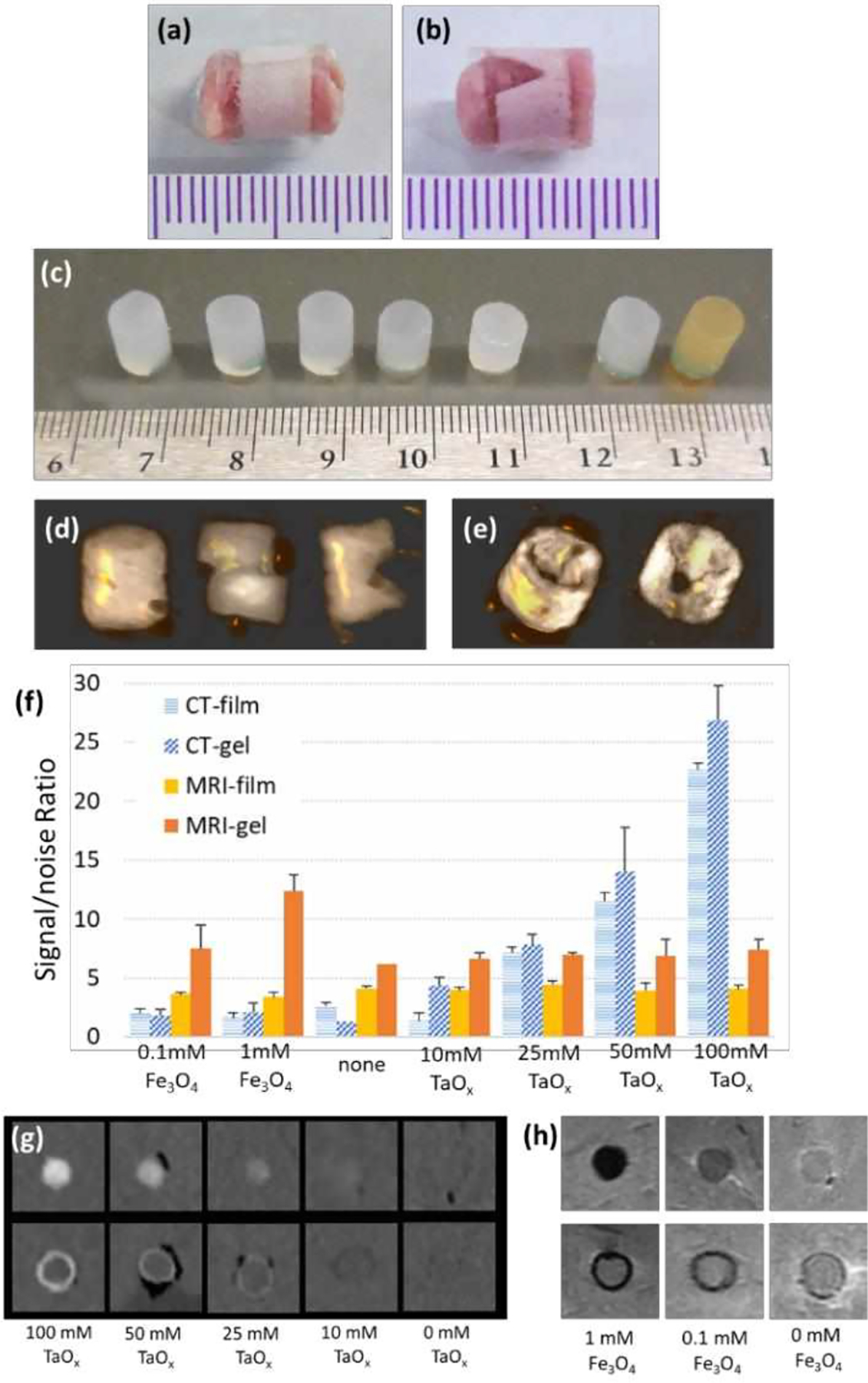
Phantoms of medical devices were constructed from gels and films incorporating nanoparticles. (a-b) PLGA films were wrapped around tissue to create (a) intact films and (b) damaged films. (c) Intact agarose gels before implantation. From left to right: no nanoparticles, 10 mM TaOx, 25 mM TaOx, 50 mM TaOx, 100 mM TaOx, 0.1 mM Fe3O4, 1 mM Fe3O4. (d-e) Intact or damaged TaOx phantoms, viewed as 3D reconstructions of CT scans: (d) gels were implanted intact, cut or gouged and (e) films were intact or notched. (f) Signal/noise ratios were calculated for each concentration of nanoparticles in films and gels. A signal/noise ratio above 10 in the nanoparticle’s preferred imaging modality, was observed to be enough contrast. This was seen in (g) CT imaging of TaOx dilutions in gels (top) and films (bottom) and (h) MRI imaging of Fe3O4 dilutions in gels (top) and films (bottom). (a-c) Scale is in mm.
As seen in Figure 1(c), gels were formed with several concentrations of hydrophilic TaOx nanoparticles: 10, 25, 50 and 100 mM. Gels were also formed with two concentrations of hydrophilic Fe3O4 nanoparticles: 0.1, 1 mM. Nanoparticles were suspended in milliQ water, followed by addition of 5% w/w agarose. The solution was heated to 60 °C and cast into reservoirs to form 7 mm thick, 15 mm diameter disks. Disks were stored at 4 °C until use. Another set of gels was fabricated without nanoparticles, for use as negative controls.
To determine the optimal concentration of nanoparticles for visualization, an initial set of imaging experiments was performed. Gels and films with nanoparticles (n = 3 per group) were implanted randomly into two lamb shanks, as described below, and imaged with CT and MRI. Images of gels were evaluated in AMIDE software. A cylindrical region of interest (ROI) was manually placed over the gels, and mean signal intensity was calculated. Values of tissue and air were recorded at 3 points per sample. Each film sample was isolated in ImageJ, and the mean signal intensity of five slices per film were analyzed by drawing an ROI around the film. The signal in air was recorded at three points per shank. Signal to noise was calculated as the mean signal intensity of the sample divided by the standard deviation of mean signal intensity of the noise, Figure 1(f–h). Concentrations of 50 mM TaOx and 1 mM Fe3O4 were chosen for all further imaging. A signal/noise ratio above 10, in the nanoparticle’s preferred imaging modality, was observed to be enough contrast (Fig 1g–h) in the dilutions of TaOx and Fe3O4 gels and films, in line with other studies.22
2.3. Radiological model
Implanted phantom geometry and size were chosen to be at the edge of the resolution of clinical imaging techniques, but within the size range of biomedical devices currently in use. All implants were cylindrical in shape to reduce imaging artefacts that can occur at sharp edges, for better comparison across imaging techniques. Prior to implantation, gel samples were cut into 6 mm cylinders. Both films and gels were hydrated overnight in milliQ water, and sonicated to remove air. Gel samples were implanted in three conditions: intact, bisected with a razor, or notched with a razor, Figure 1(d). Films were implanted either intact, or with a v-shaped notch cut into the side of the film, Figure 1(e).
To simulate the use of films as a tissue wrap, hydrated film strips were adhered to tissue tape and rolled around a gel sample (6mm in diameter). The edges of the tape were pressed together with forceps, so that the wrap could not unravel. The agarose gel was removed, and a prepared lamb biopsy, punched from the lamb shank with a biopsy punch, was inserted. The completed assembly was sonicated to remove air, and left in water until implantation.
A food-quality lamb shank was chosen as a representative tissue model for its size, and the physiological mixture of tissues. Four rows were scored into the lamb shank, 1 inch (2.5cm) deep. A 6mm biopsy punch was used to remove tissue at the bottom of the cut, at sites spaced 1 inch apart. Five phantoms, chosen at random, were inserted into the sites, Figure 2(a), and phosphate buffered saline (PBS) was injected around the implant. For shams, a biopsy was made, turned over, and reinserted back into the site. Stay stitches of vicryl (braided, 3–0, FS-1 reverse cutting, J452H Ethicon) secured each implant. Rows were sutured closed, with injection of PBS to remove air. For orientation of images, markers were placed around the implanted grid: an Eppendorf tube containing an ivory bead (CT contrast) was positioned below the tissue surface, and two mustard packs were taped onto the top (MRI contrast). The implanted lamb shank was incubated in water at 4°C overnight. Several hours prior to imaging, the lamb was removed, placed in a plastic bag and warmed to room temperature.
Figure 2.
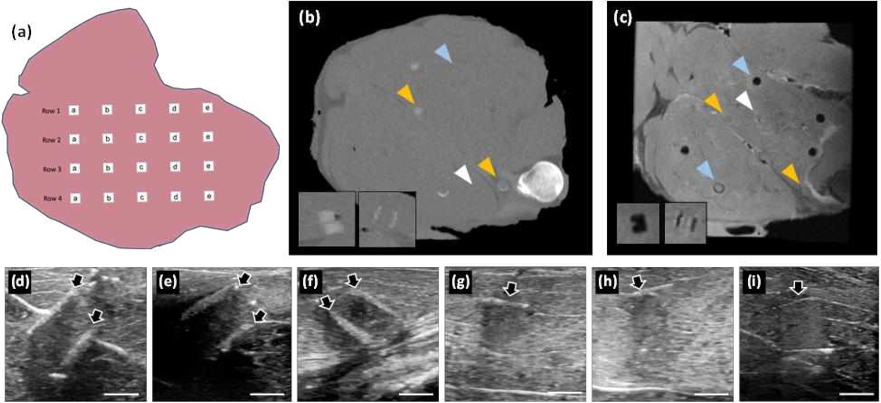
Phantoms were evaluated with clinical imaging techniques after implantation in lamb shanks. (a) A schematic of implantation. Typical cross-sections are shown after imaging with (b) CT, (c) MRI and (d-i) ultrasound. (b) Gels and films with TaOx nanoparticles were more easily seen in CT; insets are transverse views of a gel (cut) and film. (c) Phantoms with Fe3O4 nanoparticles appeared dark in MRI; insets showing transverse views of a gel (gouged) and film. Images in (b-c) are of the same lamb shank; white arrowheads: phantoms without nanoparticles, blue arrowheads: phantoms with Fe3O4, orange arrowheads: phantoms with TaOx. (d-i) Ultrasound images were taken at each phantom location: (d) intact film with Fe3O4, (e) damaged film with no nanoparticles, (f) damaged film with TaOx, (g) intact gel with no nanoparticles, (h) damaged (cut) gel with TaOx, and (i) damaged (gouged) gel with Fe3O4. Arrows mark the location of phantoms. Scale bars in (d-i): 5 mm.
To demonstrate the clinical relevance of the phantoms, the lamb shank was dissected to reveal the sciatic nerve alongside the bone. Two pre-hydrated films (5mm wide, 30mm long) were wrapped around the nerve, with either 50 mM TaOx nanoparticles or 1 mM Fe3O4 nanoparticles. The films were held in place with polypropylene sutures (Prolene, blue monofilament, 6–0, 1/2c taper) and the incision was sutured closed with vicryl suture. PBS was injected into the incision during closure to remove air. The shank was stored and imaged as before.
2.4. Imaging
All imaging was performed on clinical machines within the Michigan State University Radiology Department, operated by experienced technologists.
Computed Tomography (CT):
Imaging was performed on a clinical CT (GE Discovery, 64 slice). Scans of the entire lamb shank were taken at 120keV, following standard protocol for a head scan. The resulting images had a resolution of 430μm/pixel.
Magnetic Resonance Imaging (MRI):
A GE Sigma HDX 3.0T scanner (Waukesha, WI) was used to image the lamb shanks, using a clinical head coil. The pulse sequences consisted of an isometric fast spin-echo (FSE) proton density series with 1.0 mm voxels (34ms TE, 4500ms TR, 83kHz bandwidth, 160mm FOV, 2.0 Nex), proton density with 312.5 × 454.5 μm/pixel resolution (512 × 352 matrix, 36ms TE, 3600ms TR, 83kHz bandwidth, 1.5mm slice thickness, 0mm interslice gap, 160mm FOV, 2.0 Nex) and a fat-suppressed FSE proton density with 416.7 × 714.2 μm/pixel resolution (384×224 matrix, 32ms TE, 3400ms TR, 50kHz bandwidth, 4.0 mm slice thickness, 0 mm interslice gap, 160 mm FOV, 2.0Nex).
Ultrasound:
A GE Logiq 9 machine, with L8–18i transducer, on a thyroid setting was used for all imaging. The frequency for the scans was 9 MHz. The ultrasound technician scanned along each row, taking images where implants were identified. The resulting images had a resolution of 36 μm/pixel. In addition, the technician recorded a scan of the entire row in video format, so that radiologists could make their own assessments.
2.5. Radiological evaluation
Prior to the blinded study, radiologists were trained to detect the phantoms using a lamb shank, containing intact and damaged gels and films, imaged with all three methodologies. A map of the samples was provided to radiologists, to compare between intact and damaged samples.
For the blinded study, films (control, 50 mM TaOx, and 1 mM Fe3O4), gels (control, 50 mM TaOx, and 1 mM Fe3O4) and shams were implanted randomly into three lamb legs (n=4 for films, n=5 sham, n=4 intact gels, n=3 each cut and gouged gels). Lamb shanks were imaged via all three methods, and the radiologists were provided with the blinded data and a worksheet for each lamb leg. Two fellowship trained musculoskeletal radiologists, with 14 and 5 years of post-fellowship experience respectively, were asked to independently evaluate:
Was there an implant at each site? (Y/N)
What type of implant was there? (gel/film)
Was the implant damaged? (Y/N)
Indicate which imaging modality was most valuable for evaluating each sample.
The completed worksheets were collated by an unblinded researcher. When implanted phantom presence was not correctly identified, implanted phantoms were not assessed further, and they did not count in the calculated percentages for implant type or damage. When radiologists indicated that they used more than one imaging modality, that implanted phantom was counted in the statistics for both modalities. Results are presented as an average of the two independent readings (± standard deviation).
3. RESULTS
Lamb shanks were large enough to contain 20 implant sites, spaced roughly 1 inch (2.5 cm) apart, Figure 2(a). The placement of phantoms after implantation shifted with manipulation of the lamb shank while positioning the specimens in the clinical machines. Thus, only a subset of implanted phantoms was visible at any given cross-section in the sample. As in normal clinical practice, radiologists were able to view the lamb in multiple views (coronal, sagittal, transverse), Figure 2.
The three clinical imaging modalities collect information from different sources: x-rays, magnetism, and acoustics. As such, implanted phantoms were visible to varying degrees on each modality, particularly those which incorporated nanoparticles designed to aid in clinical diagnosis. Implanted phantoms with TaOx nanoparticles were seen most easily with CT, Figure 2(b). In MRI, implanted phantoms with Fe3O4 appeared dark, Figure 2(c), while all other implanted phantoms were visible primarily from disruption of tissue or excess PBS injected to remove air. Ultrasound images were not enhanced by the addition of nanoparticles. Successful identification of implanted phantoms in ultrasound was strictly dependent on the type of implant (gel or film) and the position of the implant in relation to the probe, Figure 2(d–i).
Overall, radiologists correctly identified whether implanted phantoms were present, Figure 3(a). The success rate for gel and film phantoms was 77% and 96%, respectively. Part of this success rate can be attributed to the tissue damage created during implantation. This was exemplified by sham implanted phantoms, which had enough tissue damage during implantation to be incorrectly identified as implanted phantoms in 50% of cases. Films were more likely to be identified as an implanted phantom by radiologists compared to gels. Unlike the gels and shams, even films without nanoparticles could appear as faint irregularities in the tissue when viewed with MRI, and to a lesser extent, in CT imaging. (The circular shape of films could not be mistaken for any other anatomical tissue, making them easier to identify.) Films were generally easier for ultrasound technicians to image as well, Figure 2 (d–f).
Figure 3.
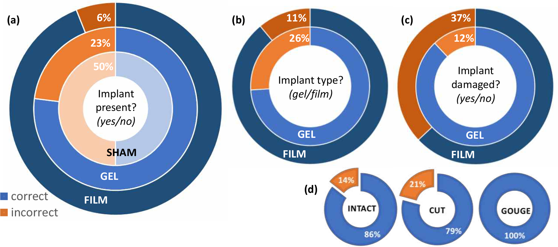
The type of implanted phantom impacted the ability of radiologists to correctly identify key features. (a) Once implanted, the presence of gels was harder for radiologists to assess, compared to films. The high level of shams marked incorrectly, indicated that the surgical approach was often mistaken for an implanted phantom. (b) When assessing implanted phantoms, films were more often identified correctly than gels. (c) Damage was harder to assess for films than gels, mostly likely due to the subtle mode of damage. However, the mode of damage also played a role in radiologists’ ability to determine if gels were damaged as well. (d) Gels with a gouge were always identified correctly, compared to those with a cut, which averaged only 79% correct.
When implanted phantoms were correctly identified, radiologists had a high success rate of correctly labeling them as gel or film, Figure 3(b). This corresponded to correctly identifying gel implants in 74% of cases and correctly identifying implanted films in 89% of cases. However, the success rate fell dramatically when determining whether implanted phantoms were intact or damaged. In particular, radiologists had a 63% success rate identifying damage in films, Figure 3(c), where the notch was relatively subtle. The effect of damage type was seen most clearly with gels. While the overall success rate in gel damage assessment was 88%, this was concentrated on the intact and cut samples. Gels with a gouge were clearly identified as damaged whenever radiologists could identify the implanted phantoms, Figure 3(d).
The addition of nanoparticles gave a clear improvement in the ability of radiologists to assess implanted phantom placement, type and damage, Table 1. Implanted phantoms without nanoparticles were correctly identified in only 69.4% of cases, and damage could be reliably detected in just over half of these. When ultrasound was recorded as a key imaging method, often in conjunction with MRI, it appeared to give better results than MRI alone. Overall, implanted phantoms were detected in 97.4 ± 2.6% and 86.1 ± 14% of cases for TaOx and Fe3O4, respectively. As predicted, implanted phantoms with TaOx were best assessed with CT, while implanted phantoms with Fe3O4 were seen most clearly in MRI. The ability to determine damage was still the most difficult question, even with nanoparticles present.
Table 1.
Nanoparticles affected the percentage of implanted phantoms identified correctly by radiologists.
| Nanoparticle | Question | Overall Correct (%) | Correct (%): individual modalities | ||
|---|---|---|---|---|---|
| CT | MRI | Ultrasound | |||
| none | phantom present | 69.4 ± 8.3 | --- | 69.0 ± 2.4 | 80.4 ± 5.4 |
| phantom type | 63.0 ± 8.4 | --- | 69.0 ± 2.4 | 41.7 ± 25 | |
| phantom damaged | 54.9 ± 9.4 | --- | 48.8 ± 15 | 83.3 ± 17 | |
| TaOx | phantom present | 97.4 ± 2.6 | 100 ± 0.0 | --- | --- |
| phantom type | 83.3 ± 11 | 97.2 ± 2.8 | --- | --- | |
| phantom damaged | 80.0 ± 9.4 | 87.9 ± 0.4 | --- | --- | |
| Fe3O4 | phantom present | 86.1 ± 14 | --- | 94.4 ± 5.6 | --- |
| phantom type | 96.2 ± 3.8 | --- | 96.2 ± 3.8 | --- | |
| phantom damaged | 87.5 ± 4.2 | --- | 91.7 ± 8.3 | --- | |
True medical devices would often be implanted deep into the tissue, and close to bone or interstitial spaces, which can be problematic for imaging modes. Thus, a more realistic model of damage was demonstrated: a sciatic nerve wrapped with a polymer film, mimicking commercially available nerve wraps. In this model, imaging was still largely dependent on the modality chosen and the type of nanoparticles incorporated, Figure 4. Ultrasound imaging was able to detect implanted phantoms with both TaOx and Fe3O4 nanoparticles. MRI and CT were only able to reliably identify one of the two implants, Figure 4(d–e).
Figure 4.
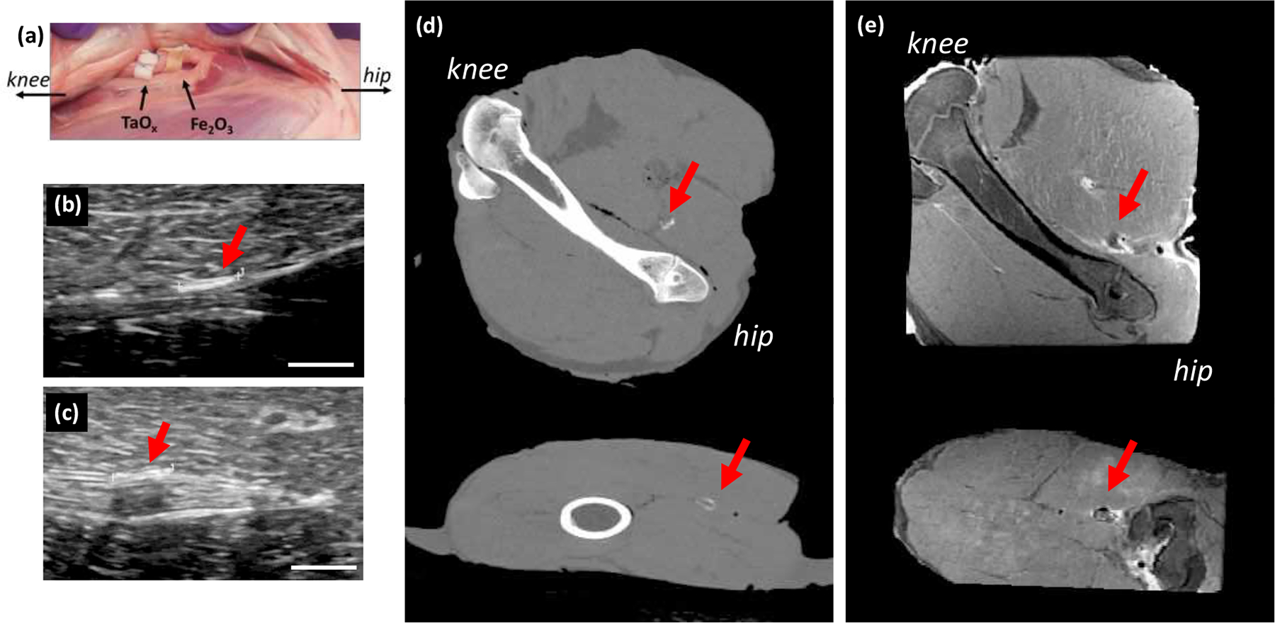
Radiological assessment of phantoms in a realistic model of nerve damage. (a) Films were sutured to the lamb sciatic nerve, acting as nerve wraps and were imaged with (b-c) ultrasound, (d) CT and (e) MRI. Ultrasound was able to detect films with (b) TaOx nanoparticles and (c) Fe3O4 nanoparticles. (d) CT imaging was only able to detect the film with TaOx nanoparticles, while (e) MRI imaging showed the Fe3O4 nanoparticle film most clearly (top: coronal view, bottom: sagittal). Arrows identify the implants. Scale bar (b-c): 5 mm.
4. DISCUSSION
In the course of diagnosis and treatment, patients will generally encounter several imaging techniques. The imaging modality chosen in the clinic is due to several factors: machine availability, cost, the type of injury, and patient comorbidities. CT and ultrasound are the cheapest and fastest imaging modalities, with MRI having the longest scan times and being more difficult to gain insurance approval. In many cases, MRI is not considered an option unless all other imaging modes are deemed inconclusive. There are other factors besides cost and availability which drive decisions on imaging. For differentiating between hard tissues like bone and surrounding soft tissues, CT is appropriate. However, CT cannot differentiate between many soft tissues, and it exposes patients to radiation. While the radiation dose per scan is limited (<15 mSv), there is an attendant risk of cancer for any ionizing radiation, and thus there is a concerted effort to minimize patient exposure over a lifetime.23 With many positive features, ultrasound does not create 3D images of tissues like MRI and CT, and the resolution drops off as the depth of tissue increases, or if the spot in question is shielded, for example behind bone.14 While contrast agents for ultrasound do exist, in the form of microbubbles of high molecular weight gases, they are limited to special applications to track perfusion in blood vessels.24 MRI has relatively high resolution and has few limitations on the types of tissues which can be resolved, depending on the scanning protocol used. Yet, aside from cost, MRI imaging can be complicated by implants, such as pacemakers25, and the scans are relatively long and often uncomfortable for patients, particularly for those who suffer from claustrophobia.
Regardless of the imaging modality chosen, the role of radiologists is to evaluate scans and render a diagnosis. The blinded study was set up to mimic clinical conditions, where there is limited information on implants and physiology. While the placement of implanted phantoms was laid out in a grid pattern, the sham implanted phantoms forced radiologists to assess each site. The use of a lamb shank added a dimension of realism, requiring radiologists to separate out the implanted phantoms from native anatomy. However, the use of any ex vivo tissue model has limitations. The lamb shank did not allow for longitudinal monitoring of the implants to assess the effects of degradation on radiological evaluation. However, if damage to the implanted phantoms was not visible in this study, without the complications of degradation present, it would not be visible after long periods of wear. Therefore, this represents the best-case scenario for assessing damage. Also, the lack of blood circulation in the lamb shank model created imaging artefacts related to air introduced during implantation. In living tissue, this would normally be resorbed quickly and not affect implant imaging. While trauma and surgery can alter tissues, these other abnormalities or disease states in patients, excluding necrotizing infection and gas gangrene, would be a significantly lesser issue for implant imaging. In the present study, saline was injected around the implanted phantoms to reduce air related artifacts in CT and ultrasound, but in some cases, the saline was visible in MRI as a bright layer surrounding implants. While not perfect, the use of lamb shanks allowed for realistic tissue variations and highlighted the variety of imaging available to radiologists. In a physiological model of sciatic nerve injury, the films acted in the same way, demonstrating clinical relevance of the results.
The phantoms used were meant to mimic clinical biomedical devices. Of all biomaterials, polymers are generally more difficult to image than ceramic and metallic implants, which have x-ray attenuation. However, polymers are used extensively, making it imperative to develop robust imaging techniques. Hydrophobic polymer films were surrogates for wraps and barriers, including tendon and nerve wraps, bladder patches, and hernia mesh.2,26 Biomedical films incorporate porosity, have thicknesses from 100 μm to several millimeters, depending on the application, and a cross-sectional area spanning the injury site. The phantom films met all of these criteria. To further mimic wraps, phantom films were secured around a piece of tissue, ensuring that radiologists evaluated a single thickness of the film, which is harder to resolve. Hydrogels represent another area of biomedical polymers, and are used as fillers for soft tissues such as cartilage and intravertebral discs.27 In addition to representing a much thicker implantable device for imaging, the hydrophilic hydrogel interacted differently with water than the hydrophobic PLGA films. Water is, of course, critical for MRI, which relies on the differential biophysical nature of water in different tissues to impart contrast to images.14
The phantoms were recognizable in all three imaging modalities tested. The cylindrical shape of the phantoms (6 mm diameter, 7 mm high) was utilized to reduce imaging artefacts related to the implant itself, allowing comparison across imaging techniques more readily. Geometries, such as sharp edges, and implants that incorporate materials that interact very differently with the energy source (x-rays, sound waves, or electromagnetic pulses) than tissue, are known to cause imaging artefacts, which radiologists must overcome.28 In addition to geometry, the size of implants can affect the ability of radiologists to detect them, particularly as they near the limits of resolution for clinical machines. In the current study, the resolution of MRI was between 300–500 μm/pixel, CT was 430 μm/pixel and ultrasound was 36 μm/pixel. Phantom film thicknesses (400–450 μm) were at the edge of resolution limits, as were fine features such as cuts in the gels, particularly when the cut did not result in misalignment of the implant pieces. The resolution the imaging machine is capable of determines the scale of features that radiologists can be expected to see. If using high-resolution imaging machines, such as those available in many research labs, the size of the phantoms could be subsequently reduced, and scaled for small animal studies. In addition to resolution, the type of excitation delivered by machines can affect the features which are visible during imaging and are regulated by many variables, including transducer geometry, energy level and pulse sequence. In this study, imaging scans were not varied from the normal protocols used to assess musculoskeletal injury, to remain true to the intent of assessing implants under clinical conditions. Also, in keeping with this goal, the size range of the phantom implants corresponds to clinical devices, including tendon and nerve wraps, and cartilage implants.
The properties of the phantoms affected the ability of radiologists to accurately locate and evaluate them, as summarized in Figure 3. Films were the easiest implanted phantoms for radiologists to identify. Radiologists correctly identified the presence films in 94% of cases. Wrapping the films led to circular shapes being present within the tissue that potentially aided radiologists. When the phantom was a gel, its presence was correct only 77% of the time. In almost a third of these cases (26%), those gels were subsequently classified as films by the radiologists, likely due to misinterpretation of a layer of water surrounding the implant. As in the present model, surgery and tissue injury are likely to complicate the imaging of implants in patients. The degree of complication this poses for radiologists depends on the type of implant, but is typically small, as they are trained to separate what is surgical from what is pathologic. In the case of the scaffolds studied here, the MRI appearance of air, which is introduced into the surgical tract during implantation, is similar to the appearance of the scaffolds themselves which does, in fact, complicate their assessment in the immediate post-implantation period. Ultrasound was similarly affected, and CT less so. The magnitude of this would be similar to other implants of a comparable size, although as noted previously, the effect would be short-lived in patients.
Damage was more difficult for radiologists to assess in films than gels. Only 63% of films were correctly identified as intact or damaged, compared to 88% in gels. The type of damage also appeared to be a significant factor in radiologists’ ability to detect it. Gels with gouges were always correctly identified, compared to the more subtle cut mode of damage. These numbers reflect all gels and films, whether they contained imaging particles or not, but the trends were consistent across all groups when evaluated individually.
There is a clear advantage to the inclusion of imaging aides when designing medical devices, particularly those which need to be followed up longitudinally. Phantoms without nanoparticles were missed by radiologists in approximately 40% of cases. Most importantly, without nanoparticles, determination of implant damage was practically guesswork, as radiologists correctly identified damage in only 54% of implants. Nanoparticles were used as a versatile system for adding imaging contrast into both the hydrophilic and hydrophobic matrices. Regardless of the type of implanted phantom, nanoparticle addition allowed radiologists to correctly identify implanted phantom presence over 86% of the time. This number was even greater when the primary imaging mode chosen by the radiologist matched with the nanoparticle’s intended modality. Importantly, the addition of nanoparticles also made it easier for radiologists to assess implanted phantom damage, correctly identifying over 80% of damaged implanted phantoms.
4.1. Design recommendations
To design implantable devices with imaging in mind, it is important to know and understand the types of interventions used for the target tissue and how radiologists typically approach diagnosis. With so many factors influencing each imaging decision, unilateral guidance on the clinical imaging for diseases is unlikely to be developed. For designers and engineers of implantable biomedical devices, choosing a preferred imaging modality must therefore be based on the tissue being treated, the physical location of the implant, and the information which is required.
Tissue being treated:
Hard tissues such as bone are most easily resolved in CT. However, CT can still resolve certain soft tissues like sciatic nerve, particularly when these tissues are surrounded by a layer of fat. If alignment of an implantable biomedical device within soft tissue is critical, MRI or ultrasound may be the most useful imaging techniques.
Physical location of the implantable biomedical devices:
The anatomical site of an implantable biomedical device may raise imaging challenges. Ultrasound is the cheapest methodology, and may be most accessible. However, devices located deep in the body, or near organs which contain air, may be outside of the optimal range of ultrasound. CT and MRI do not have those limitations, but they can experience distortions near metallic implants.29 While expensive and potentially difficult to access, MRI may be the only viable imaging modality if the assessment of the implant relies on differentiating one or more soft tissues.
Implantable biomedical device information:
Placement of a device is not the only information that can be sought with clinical monitoring. Device degradation may be important or, as noted in this study, implantable biomedical device damage may be the key issue for radiologists to assess. In these cases, resolving all of the tissues surrounding the implant may not be necessary. Therefore, an implantable device which is visible in CT, even one intended exclusively to repair soft tissues, might be more cost effective and allow for faster diagnosis than one which required MRI. In Figure 4, for example, while the nerve was not visible in CT, the state of the implanted phantom could be readily assessed.
An important point when considering clinical monitoring, is that there are different constraints on imaging in the clinic. The type of machines available in clinical radiology departments are not equal to the ultra-high resolution systems in many research labs. Important implantable biomedical device features must be resolvable at lower resolution to be clinically useful. Another key point is that imaging of implantable biomedical devices should align with current protocols. Individual MRI scans, for example, should generally not exceed 10 minutes, as patients cannot remain motionless, and the total scan time must fit into the normal 30–60 minute window allotted to MRI appointments.
To remain within normal clinical protocols, the imaging for this study was performed within a clinical setting. Thus, the type of information probed was limited to routine scans. However, as new imaging techniques develop, the way in which clinical imaging is performed on implantable biomedical devices will change. For example, ultrasound elasticity imaging has been introduced for applications such as monitoring liver fibrosis.30 Unlike traditional ultrasound, elasticity imaging maps the stiffness of tissue, making it a potential technique for monitoring degradation and tissue integration of implantable biomedical devices.31 Contrast agents for ultrasound, while currently limited to imaging blood vessel perfusion on short time intervals (< 10 minutes), might eventually be utilized for measuring tissue integration of implants, which often follows blood vessel ingrowth.24 Additionally, ultra-short echo time MRI has been used to more specifically detect contrast from iron oxide nanoparticles.32 In CT, photon counting spectral CT could be used to precisely detect x-ray attenuation from TaOx.33 It is hoped that as medical imaging progresses, more of these techniques will become available for use by device engineers, improving the quality and usefulness of medical devices and patient care. Other areas of active research include smart implants, or those incorporating sensors, which can collect and transmit data collected in situ regarding the tissue environment.34 Integrating these novel approaches with medical imaging offers yet more exciting possibilities in the future.
5. CONCLUSIONS
There are many implantable biomedical devices which could benefit from longitudinal monitoring in a clinical setting. Phantoms, mimicking films and gels, were successfully produced with and without imaging agents, in the form of nanoparticles (50 mM TaOx and 1 mM Fe3O4). Once implanted, radiologists were able to identify the presence of implanted phantoms over 80% of the time. The introduction of nanoparticles into implanted phantoms improved radiologists’ ability to evaluate implanted phantom presence, type and damage. Careful consideration of eventual clinical imaging modality should be taken early in biomedical device design stages and interplay between imaging physics, contrast agent design and biomaterial fabrication will be key to diagnostic monitoring of implantable biomedical devices in the future.
ACKNOWLEDGMENT
The authors would like to thank the technologists at the MSU Radiology Department for their help collecting data for this publication.
Funding Sources
This research did not receive any specific grant from funding agencies in the public, commercial, or not-for-profit sectors.
ABBREVIATIONS
- MRI
magnetic resonance imaging
- CT
computed-tomography
- PLGA
poly(L-lactide-co-glycolide)
- TaOx
tantalum oxide nanoparticles
- Fe3O4
iron oxide nanoparticles
REFERENCES
- 1.Kaul H; Ventikos Y On the genealogy of tissue engineering and regenerative medicine. Tissue Eng.: Part B 2015, 21(2), 203–217, DOI: 10.1089/ten.teb.2014.0285. [DOI] [PMC free article] [PubMed] [Google Scholar]
- 2.Pawelec KM; Koffler J; Shahriari D; Galvan A; Tuszynski MH; Sakamoto J Microstructure and in vivo characterization of multi-channel nerve guidance scaffolds. Biomed. Mater 2018, 13, 044104, DOI: 10.1088/1748-605X/aaad85. [DOI] [PubMed] [Google Scholar]
- 3.Pawelec KM; Wardale RJ; Best SM; Cameron R The effects of scaffold architecture and fibrin gel addition on tendon cell phenotype. J. Mater. Sci. Mater. Med 2015, 26, 5349, DOI: 0.1007/s10856-014-5349-3. [DOI] [PubMed] [Google Scholar]
- 4.Buckley CT; Hoyland JA; Fuji K; Pandit A; Iadtris JC; Grad S Critical aspects and challenges for intervertebral disc repair and regeneration - harnessing advances in tissue engineering. JOR Spine 2018, 1, e1029, DOI: 10.1002/jsp2.1029. [DOI] [PMC free article] [PubMed] [Google Scholar]
- 5.Simons MP; Smietanski M; Bonjer HJ; Bittner R; Miserez M; Aufenacker TJ; Fitzgibbons RJ; Chowbey PK; Tran HM; Sani R; Berrevoet F; Bingener J; Bisgaard T; Bury K; Campanelli G; Chen DC; Conze J; Cuccurullo D; de Beaux AC; Eker HH; Fortelny RH; Gillion JF; van den Heuvel BJ; Hope WW; Jorgensen LN; Klinge U; Koeckerling F; Kukleta JF; Konate Il; Liem AL; Lomanto D; Loos MJA; Lopez-Cano M; Misra MC; Montgomery A; Morales-Conde S; Muysoms FE; Neibuhr H; Nordin P; Pawlak M; van Ramshorst GH; Reinpold WMJ; Sanders DL; Schouten N; Smedberg S; Simmermacher RKJ; Tumtavitikul S; van Veenendaal N; Weyhe D; Wijsmuller AR International guidelines for groin hernia management. Hernia 2018, 2(1), 1–165, DOI: 10.1007/s10029-017-1668-x. [DOI] [PMC free article] [PubMed] [Google Scholar]
- 6.Mayer S; Decaluwe H; Ruol M; Manodoro S; Kramer M; Till H; Deprest J Diaphragm repair with a novel cross-linked collagen biomaterial in a growing rabbit model. PLOS One 2015, 10(7), e0132021, DOI: 10.1371/journal.pone.0132021. [DOI] [PMC free article] [PubMed] [Google Scholar]
- 7.Jacobs J; Mavroudis C; Quintessenza J; Chai P; Pasquali S; Hill K; Vricella L; Jacobs M; Dearani J; Cameron D Reoperations for pediatric and congenital heart disease: An analysis of the society of thoracic surgeons (STS) congenital heart surgery database. Semin. Thorac. Cariovasc. Surg. Pediatr. Car. Surg. Annu 2014, 17, 2–8, DOI: 10.1053/j.pcsu.2014.01.006. [DOI] [PMC free article] [PubMed] [Google Scholar]
- 8.Szulc DA; Cheng H-LM One-step labeling of collagen hydrogels with polydopamine and manganese porphyrin for non-invasive scaffold tracking on magnetic resonance imaging. Macromol. Biosci 2019, 19, 1800330, DOI: 10.1002/mabi.201800330. [DOI] [PubMed] [Google Scholar]
- 9.Erol A; Rosberg DBH; Hazer B; Goencue BS Biodegradable and biocompatible radiopaque iodinated poly-3-hydroxy butyrate: synthesis, characterization and in vitro/in vivo x-ray visibility. Polym. Bull 2020, 77, 275–289, DOI: 10.1007/s00289-019-02747-6. [DOI] [Google Scholar]
- 10.Fathi-Achachelouei M; Knopf-Marques H; da Silva CER; Barthes J; Bat E; Tezcaner A; Vrana NE Use of nanoparticles in tissue engineering and regenerative medicine. Front. Bioeng. Biotechnol 2019, 7, 113, DOI: 10.3389/fbioe.2019.00113. [DOI] [PMC free article] [PubMed] [Google Scholar]
- 11.Baetke SC; Lammers T; Kiessling T Applications of nanoparticles for diagnosis and therapy of cancer. Br. J. Radiol 2015, 88, 20150207, DOI: 10.1259/bjr.20150207. [DOI] [PMC free article] [PubMed] [Google Scholar]
- 12.Man F; Lammers T; de Rosales RTM Imaging nanomedicine-based drug delivery: a review of clinical studies. Mol. Imaging Biol 2018, 20, 683–695, DOI: 10.1007/s11307-018-1255-2. [DOI] [PMC free article] [PubMed] [Google Scholar]
- 13.Wolf F; Paefgen V; Winz O; Mertens M; Koch S; Gross-Weege N; Morgenroth A; Rix A; Schnoering H; Chalabi K; Jockenhoevel S; Lammers T; Mottaghy F; Kiessling F; Mela P MR and Pet-CT monitoring of tissue-engineered vascular grafts in the ovine carotid artery. Biomaterials 2019, 216, 119228, DOI: 10.1016/j.biomaterials.2019.119228. [DOI] [PubMed] [Google Scholar]
- 14.Wallyn J; Anton N; Akram S; Vandamme TF Biomedical imaging: principles, technologies, clinical aspects, contrast agents, limitations and future trends in nanomedicines. Pharm. Res 2019, 36, 78, DOI: 10.1007/s11095-019-2608-5. [DOI] [PubMed] [Google Scholar]
- 15.Chakravarty S; Unold J; Shuboni-Mulligan DD; Blanco-Fernandez B; Shapiro EM Surface engineering of bismuth nanocrystals to counter dissolution. Nanoscale 2016, 8, 13217–13222, DOI: 10.1039/c6nr02171a. [DOI] [PMC free article] [PubMed] [Google Scholar]
- 16.Mertens ME; Hermann A; Buehren A; Olde-Damink L; Moeckel D; Gremse F; Ehling J; Kiessling F; Lammers T Iron oxide-labeled collagen scaffolds for non-invasive MR imaging in tissue engineering. Adv. Funct. Mater 2014, 24, 754–762, DOI: 10.1002/adfm.201301275. [DOI] [PMC free article] [PubMed] [Google Scholar]
- 17.Forton SM; Latourette MT; Parys M; Kiupel M; Shahriari D; Sakamoto JS In vivo microcomputed tomography of nanocrystal-doped tissue engineered scaffolds. ACS Biomater. Sci. Eng 2016, 2, 508–516, DOI: 10.1021/acsbiomaterials.5b00476. [DOI] [PMC free article] [PubMed] [Google Scholar]
- 18.Martin JT; Milby AH; Ikuta K; Poudel S; Pfeifer CG; Elliott DM; Smith HE; Mauck RL A radiopaque electrospun scaffold for engineering fibrous musculoskeletal tissues: Scaffold characterization and in vivo applications. Acta Biomater. 2015, 26, 97–104, DOI: 10.1016/j.actbio.2015.08.001. [DOI] [PMC free article] [PubMed] [Google Scholar]
- 19.Gil C; Tomov ML; Theus AA; Cetnar S; Mahmoudi M; Serpooshan V In vivo tracking of tissue engineered constructs. Micromach. 2019, 10, 474, DOI: 10.3390/mi10070474. [DOI] [PMC free article] [PubMed] [Google Scholar]
- 20.Chakravarty S; Hix JML; Wiewiora KA; Volk MC; Kenyon E; Shuboni-Mulligan DD; Blanco-Fernande B; Kiupel M; Thomas J; Sempere LF; Shapiro EM Tantalum oxide nanoparticles as versatile contrast agents for x-ray computed tomography. Nanoscale 2020, 12, 7720–7734, DOI: 10.1039/d0nr01234c. [DOI] [PMC free article] [PubMed] [Google Scholar]
- 21.Granot D; Nkansah MK; Bennewitz MF; Tang KS; Markakis EA; Shapiro EM Clinically viable magnetic poly(lactide-co-glycolide) particles for MIR-based cell tracking. Magn. Reson. Med 2014, 71, 1238–1250, DOI: 10.1002/mrm.24741. [DOI] [PMC free article] [PubMed] [Google Scholar]
- 22.Finamore TA; Curtis TE; Tedesco JV; Grandfield K; Roeder RK Nondestructive, longitudinal measurement of collagen scaffold degradation using computed tomography and gold nanoparticles. Nanoscale 2019, 11, 4345, DOI: 10.1039/c9nr00313d. [DOI] [PubMed] [Google Scholar]
- 23.Shao Y-H; Tsai K; Kim S; Wu Y-J; Demissie K Exposure to tomographic scans and cancer risks. JNCI Cancer Spectrum 2020, 4(1), pkz072. [DOI] [PMC free article] [PubMed] [Google Scholar]
- 24.Chong WK; Papadopoulou V; Dayton PA Imaging with ultrasound contrast agents: current status and future. Abdom. Radiol 2018, 43, 762–772, DOI: 10.1007/s00261-018-1516-1. [DOI] [PubMed] [Google Scholar]
- 25.Russo RJ; Costa HS; Silva PD; Anderson JL; Arshad A; Biederman RWW; Boyle NG; Frabizzio JV; Birgersdotter-Green U; Higgins SL; Lampert R; Machado CE; Martin ET; Rivard AL; Rubenstein JC; Shaerf RHM; Schwartz JD; Shah DJ; Tomassoni GF; Tominaga GT; Tonkin AE; Uretsky S; Wolff SD Assessing the risks associated with MRI in patients with a pacemaker or defibrillator. N. Engl. J. Med 2017, 376, 755–764. [DOI] [PubMed] [Google Scholar]
- 26.Costa A; Adamo S; Gossetti F; D’Amore C; Ceci F; Negro P; Bruzzone P Biological scaffolds for abdominal wall repair: future in clinical application? Materials 2019, 12, 2375, DOI: 10.3390/ma12152375. [DOI] [PMC free article] [PubMed] [Google Scholar]
- 27.Pina S; Ribeiro VP; Marques CF; Maia FR; Silva TH; Reis RL; Oliveira JM Scaffolding strategies for tissue engineering and regenerative medicine applications. Materials 2019, 12, 1824, DOI: 10.3390/ma12111824. [DOI] [PMC free article] [PubMed] [Google Scholar]
- 28.Rousselle A; Amelot A; Thariat J; Jacob J; Mercy G; De Marzi L; Feuvret L Metallic implants and CT artefacts in the CTV area: Where are we in 2020? Cancer/Radiotherapie 2020, 24, 658–666, DOI: 10.1016/j.canrad.2020.06.022. [DOI] [PubMed] [Google Scholar]
- 29.Do TD; Sutter R; Skornitzke S; Weber M-A CT and MRI techniques for imaging around orthopedic hardware. Fortschr. Roentgenstr 2018, 190, 31–41, DOI: 10.1055/s-0043-118127. [DOI] [PubMed] [Google Scholar]
- 30.Sigrist RMS; Liau J; El Kaffas A; Chammas MC; Willmann JK Ultrasound elastography: review of techniques and clinical applications. Theranostics 2017, 7, 1303–1329, DOI: 10.7150/thno.18650. [DOI] [PMC free article] [PubMed] [Google Scholar]
- 31.Yu J; Takanari K; Hong Y; Lee K-W; Amoroso NJ; Wang Y; Wagner WR; Kim K Noninvasive characterization of polyurethene-based tissue constructs in a rat abdominal repair model using high frequency ultrasound elasticity imaging. Biomaterials 2013, 34(11), 2701–2709, DOI: 10.1016/j.biomaterials.2013.01.036. [DOI] [PMC free article] [PubMed] [Google Scholar]
- 32.Kaggie JD; Markidesm H; Graves MJ; MacKay J; Houston G; El Haj A; Gilbert F; Henson F Ultra short echo time MRI of iron-labelled mesenchymal stem cells in an ovine osteochondral defect model. Sci. Rep 2020, 10, 8451, DOI: 10.1038/s41598-020-64423-4. [DOI] [PMC free article] [PubMed] [Google Scholar]
- 33.Cuccione E; Chhour P; Si-Mohamed S; Dumot C; Kim J; Hubert V; Da Silva CC; Vandamme M, Chereul E; Balegamire J; Chevalier Y; Berthezene Y; Boussel L; Douek P; Cormode DP; Wiart M Multicolor spectral photon counting CT monitors and quantifies therapeutic cells and their encapsulating scaffold in a model of brain damage. Nanotheranostics 2020, 4, 129–141, DOI: 10.7150/ntno.45354. [DOI] [PMC free article] [PubMed] [Google Scholar]
- 34.Ledet EH; Liddle B; Kradinova K; Harper S Smart implants in orthopedic surgery, improving patient outcomes: a review. Innov Entrep Health 2018, 5, 41–51. [DOI] [PMC free article] [PubMed] [Google Scholar]