

Abstract
This paper presents the design and validation of a backdrivable powered knee orthosis for partial assistance of lower-limb musculature, which aims to facilitate daily activities in individuals with musculoskeletal disorders. The actuator design is guided by design principles that prioritize backdrivability, output torque, and compactness. First, we show that increasing the motor diameter while reducing the gear ratio for a fixed output torque ultimately reduces the reflected inertia (and thus backdrive torque). We also identify a tradeoff with actuator torque density that can be addressed by improving the motor’s thermal environment, motivating our design of a custom Brushless DC motor with encapsulated windings. Finally, by designing a 7:1 planetary gearset directly into the stator, the actuator has a high package factor that reduces size and weight. Benchtop tests verify that the custom actuator can produce at least 23.9 Nm peak torque and 12.78 Nm continuous torque, yet has less than 2.68 Nm backdrive torque during walking conditions. Able-bodied human subjects experiments (N=3) demonstrate reduced quadriceps activation with bilateral orthosis assistance during lifting-lowering, sit-to-stand, and stair climbing. The minimal transmission also produces negligible acoustic noise.
I. INTRODUCTION
Traditionally, exoskeletons (i.e., powered orthoses) aid paraplegic individuals with little to no voluntary movement, e.g., following a severe stroke or spinal cord injury [1], [2]. As a result, many exoskeletons are designed for high torque output (typically using highly geared motors) to fully support the legs. However, a larger population with musculoskeletal disorders would benefit from partial assistance of their musculature rather than full assistance. This includes 27 million people with osteoarthritis [3] and 66 million people with lower back pain (LBP) [4] in the USA alone. Weak quadriceps musculature is a significant contributing factor to the persistence and progression of both conditions, which can potentially be addressed by assistive knee torques. In the case of knee osteoarthritis, this assistance would mitigate pain by reducing high forces at the patellofemoral and tibiofemoral joints during demanding activities such as sit-stand (STS) and stair climbing [5], [6]. Likewise, LBP that results from repetitive lifting and lowering (L&L) tasks could benefit from partial assistance, as fatigued quadriceps contribute to poor lifting posture [7]. New partial-assist powered orthoses are needed for these purposes.
The design of partial-assist powered orthoses must balance multiple high-level goals: 1) minimize the torque required by the user to backdrive (i.e., freely rotate) the actuator during voluntary movements, 2) minimize weight and size for a noncumbersome design, and 3) provide biomechanically-relevant torque assistance. Backdrivability is defined as the ratio between the actuator’s output torque and its backdrive torque [8]. There are several methods to achieve high backdrivability, e.g., closed-loop force control of a series elastic actuator (SEA) [9], [10]. However, SEAs tend to have low output torque, complex system architecture, large size/weight, and/or limited force/torque control bandwidth. The powered knee orthosis in [8] uses a hydraulic actuator to achieve high backdrivability without sacrificing output torque, but electric motors tend to be much more efficient than hydraulic actuators.
In recent years, legged robots have used torque-dense electric motors with low transmission ratios (i.e., quasi-direct drive actuators) to achieve highly dynamic motions, compliance to impacts, regenerative braking, accurate torque control, and reduced acoustic noise [11]–[14]. Quasi-direct drives have low reflected inertia and friction, which results in low mechanical impedance and high backdrivability [12]. However, these prior works lack analysis on how backdrive torque scales with certain properties of the actuator design, which is a key concern for partial-assist orthoses. This application also presents new constraints on managing the heat generated by the high winding currents required by the high-torque motor. For example, a forced liquid cooling system can reduce the motor winding temperature to increase the motor’s torque output rating [15], [16], but liquid cooling systems add more mass and bulk than desired for daily-use orthoses.
Our previous work [17] implemented a torque-dense electric motor with a low-ratio (24:1) transmission in a knee-ankle exoskeleton intended for stroke rehabilitation, which has high torque requirements. This actuator had a static backdrive torque of 1.5 Nm and a peak dynamic backdrive torque of 8 Nm during walking [18]. However, the previously discussed thermal condition was the main factor limiting the rated peak (60 Nm) and continuous (30 Nm) output torques of the actuator. This exoskeleton was also too bulky and heavy (4.88 kg), and possibly overdesigned, for everyday use by individuals with musculoskeletal disorders. By further reducing the gear ratio to 8.55:1 (and sacrificing output torque), Su et al. [19] recently implemented a highly backdrivable, partial-assist knee orthosis using a torque-dense electric motor. However, the continuous torque of 6 Nm may be insufficient for more demanding activities (e.g., STS or repetitive L&L). The distributed actuator design may also make this orthosis too heavy (3.2 kg) and bulky for everyday use.
Weight and size are also important design constraints for a partial-assist powered orthosis. Most exoskeletons use off-the-shelf motors and gearboxes, which lead to low package factors. The package factor is defined as the ratio between the mass of the functional components (e.g., gears, rotor) and the support components (e.g., bearings, frame). For example, the Robodrive motor in the prosthetic leg in [14] is 1.3 kg but its core components (stator, rotor) are only 0.37 kg, resulting in a low package factor. To our knowledge, actuator package factor has not been directly considered in the exoskeleton literature. A higher package factor was achieved in a small legged robot by designing a 6:1 planetary gearbox into the inner diameter of a torque-dense T-motor [20], [21]. This lightweight, compact design has a peak torque of 17 Nm and a continuous torque of 5 Nm, but the latter may be insufficient for human assistance.
Our preliminary work [22] demonstrated design innovations to improve the backdrivability, size, and weight of a powered knee orthosis (Fig. 1). First, we designed a custom BLDC motor with encapsulated windings to improve its thermal environment and thus increase its torque density (output torque capability divided by mass). This allowed the use of a smaller gear ratio (7:1), which greatly increased backdrivability. Second, we custom made all core components of the actuator, designing the planetary gears inside the stator. By sharing the supporting components, we increased the package factor with a total actuator mass of 1.15 kg. The resulting (unilateral) orthosis facilitated reduced quadriceps activation in a single able-bodied subject during a repetitive L&L activity.
Fig. 1.
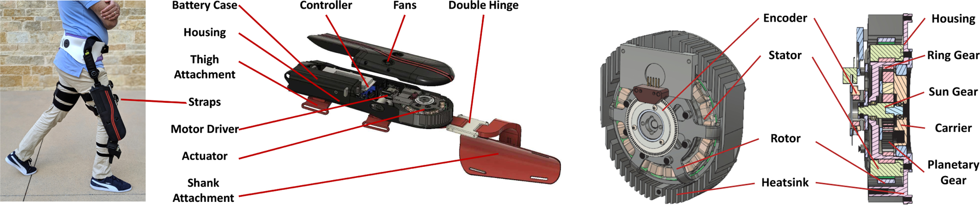
Left: Photo and CAD model of the powered knee orthosis. The shank attachment, which incorporates a double hinge as well as other linear and angular adjustments, allows for a wide range of leg curvatures to experience a comfortable fit. Right: CAD rendering of the actuator design with high package factor. A single-stage planetary transmission is nested inside of the stator. The housing supports both the stator and ring gear.
This paper extends the preliminary work [22] by offering three design principles for partial-assist orthosis actuators and demonstrating the benefits of updated, bilateral knee orthoses for multiple use cases. First, we analytically show that for a fixed actuator output torque, increasing the motor diameter while reducing the gear ratio ultimately reduces the reflected inertia and thus backdrive torque of the actuator. Second, we show a corresponding trade-off in actuator torque density that can be addressed by improving the motor’s thermal environment with encapsulated windings. Third, increasing the diameter of an outer-rotor BLDC motor also provides space for integrating the gears into the stator to further improve torque density through the package factor. In addition to these formalized principles, this paper revises the custom rotor design to achieve a 20% higher torque constant than in [22]. New benchtop experiments verify that the custom actuator can produce at least 23.9 Nm peak torque and 12.78 Nm continuous torque yet has less than 2.68 Nm backdrive torque during walking conditions. Finally, we extend the human subjects study to N = 3 with bilateral knee orthoses supporting multiple activities: STS, L&L, and stair ascent/descent. For all activities, mean effort and peak activation of the quadriceps muscles were smaller with the orthosis than without it, except for the (biarticular) rectus femoris in stair climbing. Moreover, the quasi-direct drive design produced negligible acoustic noise, which is an important (but rarely addressed) practical consideration for daily use. These results suggest the presented design has potential implications for preventing fatigue-induced compensations in repetitive tasks or reducing osteoarthritic pain during activities of daily living.
II. Design Principles for Partial-assist Actuators
While exoskeleton actuators are typically designed for high torque density (torque output over mass), recent designs have investigated backdrivability for improved human interaction [19], [23] and energy harvesting [24]. The challenge of designing a backdrivable actuator lies in balancing the output and backdrive torques. Although it is well known that increasing the motor diameter improves the torque density of quasi-direct drives for legged robots [11], [12], prior analyses have not explicitly shown how motor diameter affects backdrive torque.
1). Increase Motor Diameter for Higher Backdrivability:
A major contribution to the actuator’s backdrive torque during human locomotion is the inertia of the motor reflected through the transmission [12], [14]. Assuming the contribution of friction is negligible (as is the case in quasi-direct drive actuators [11]–[14]), the backdrive torque can be expressed as Tb = Ia∙α, where α is the acceleration rate, and the actuator inertia Ia = Ir R2 for rotor inertia Ir and gear ratio R. Hence, backdrive torque scales with the gear ratio squared, so backdrivability is maximized by minimizing the transmission ratio. However, there is an inherent trade-off with actuator output torque for a fixed motor torque.
Assuming the transmission has ideal efficiency and the gear ratio R is given by actuator output torque Ta over motor output torque Tm, we can express backdrive torque Tb = Ir ∙(Ta/Tm)2∙α. To further evaluate backdrive torque, we fix the backdrive acceleration rate and the actuator torque output as design specifications. As a result, the backdrive torque is related to the motor torque output and rotor inertia:
| (1) |
Prior work [11], [12] has shown how a motor’s torque output and inertia relate to the diameter of the motor’s airgap dgap, which scales with motor diameter (not to be confused with the thickness of the gap between the rotor and stator). Under certain assumptions in [11], [12], the motor torque and the rotor inertia Moreover, the motor mass Mm ∝ dgap, so motor torque density Tm/Mm ∝ dgap. By using these relationships, we can rewrite (1) as
| (2) |
Hence, actuator backdrive torque is inversely proportional to airgap diameter, i.e., a larger diameter motor reduces the actuator’s backdrive torque while maintaining the actuator’s output torque. This further implies that backdrivability (Ta/Tb) scales with dgap. The increased motor diameter will also be advantageous for our integrated transmission design in Section III.
However, there are two practical constraints on motor diameter that will limit the backdrivability that can be achieved. First, the design cannot exceed the diameter of the human knee joint. Second, there is a trade-off with actuator mass Ma that must be balanced in exoskeleton applications. In particular, our assumption that gear ratio R = Ta/Tm with fixed Ta implies . Moreover, if we assume the transmission mass is fixed (i.e., invariant to small changes in R), then the actuator torque density scales inversely proportional to airgap diameter:
| (3) |
We aim to achieve the greatest backdrivability possible while maintaining a compact and lightweight orthosis design. The next design principle will allow us to improve the actuator torque density without sacrificing backdrivability.
2). Increase Torque Density Through Thermal Environment:
The actuator’s torque density can be increased by improving the motor’s thermal environment, which involves surface convection and radiation as well as thermal conduction between the copper wire and the stator core. Forced air or forced liquid cooling can enhance convection [15], [16] but may not be practical in exoskeletons with constrained size and weight. A more practical method is to improve the thermal conduction between the copper and stator core. The insulation layer placed between the copper wire and stator slot (to prevent a short connection) is typically made of a material with poor thermal conductivity, e.g., nylon. As a result, the winding heat is very difficult to transfer to the environment, even with a heat sink on the stator case [16]. To solve this problem we will use encapsulated windings in Section III–B. Encapsulation uses a resin material with high thermal conductivity to fill the air gaps between the core and the winding (Fig. 2), which can distribute the heat from the winding to the stator directly [25].
Fig. 2.
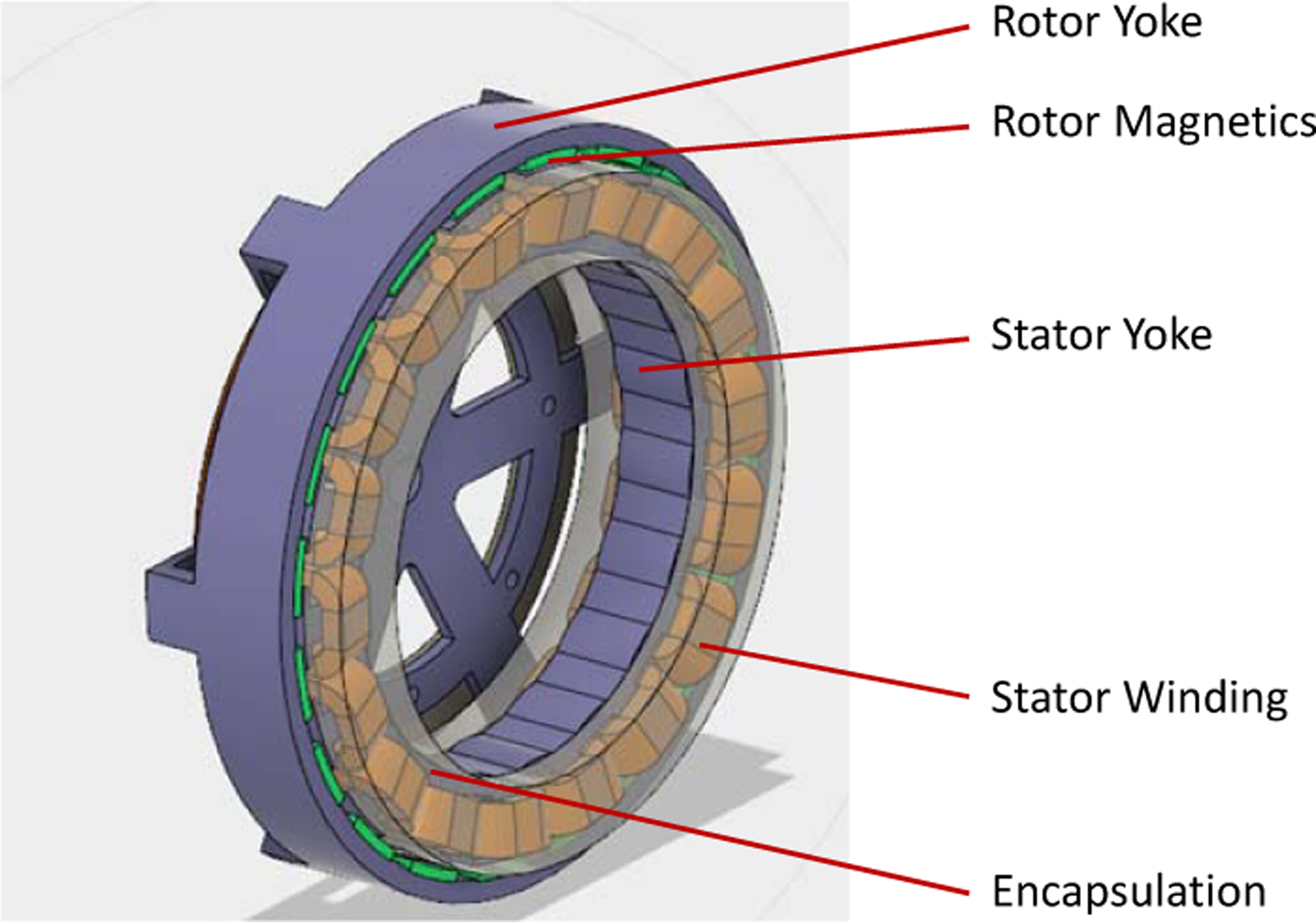
CAD rendering of the custom outer-rotor BLDC motor. The N35 permanent magnets are green, the windings are yellow, and the encapsulation material is partially transparent. The stator core and the rotor yoke are blue.
While encapsulation improves the motor’s torque density, we can also improve actuator torque density and size by integrating the gears and stator for a high package factor.
3). Integrate Gears and Stator for High Package Factor:
Overall actuator mass and size can be reduced by increasing the package factor, which is the ratio of masses for functional components over support components. Functional components tend to be constrained by material properties (e.g., gear’s mechanical strength, stator core’s magnetic saturation). Reducing the mass of supporting components is a more practical way to increase package factor and torque density. This can be achieved by 1) optimizing space usage with custom-designed core components, 2) minimizing supporting components, and 3) avoiding use of unnecessary connection components (e.g., coupler) between different functional components.
In particular, a large motor diameter presents an opportunity to design a small gearset directly inside the motor. An outer-rotor motor can produce higher torque than an inner-rotor motor due to a larger airgap diameter [26]. Outer-rotor motors also have empty space inside of the stator (Fig. 2), which is not utilized in traditional actuator designs. To reduce the thickness and weight of the assembly, we will design a single-stage transmission to fit inside the stator. A variety of transmission styles are available, including cycloid gears [27] and planetary gears [14], [17], and we will choose the latter in Section III–A.
In summary, we propose that a larger diameter motor will 1) increase backdrivability and 2) provide space to integrate gears inside the stator for a high package factor. The improved thermal environment will increase output torque without increasing weight or backdrive torque. These three principles will guide our actuator design in the following section.
III. Actuator Design and Implementation
A prior study [28] observed reduced knee moments during walking after severe osteoarthritis (OA) when compared to the asymptomatic pool. Peak knee extension and flexion moments were reduced by 15 Nm and 25.6 Nm, respectively. Based on the knee moment waveforms in [28, Fig. 1], we calculated the mean reduction in absolute knee moment to be 7.3 Nm for an 80 kg individual with OA. Furthermore, a study of lifting techniques [29] found that the rectus femoris muscle has 16.24% more activity during squatting, which is biomechanically sound, compared to stooping, which is known to cause lower back injuries. Based on maximum voluntary contraction (MVC) reference data from [30], this translates to a 27.9 Nm increase in knee torque on average. To design an orthosis that can both compensate for osteoarthritic deficits and facilitate sound L&L technique, we set the actuator design goals at 13 Nm continuous torque and 25 Nm peak torque.
A. Motor and Transmission Design
The airgap diameter of the motor was chosen as 95.2 mm to maximize backdrivability via (2) within the size constraints of the knee joint. Based on this diameter, this section presents the design of a custom outer-rotor BLDC motor (Fig. 2) with a rated torque ≥1.85 Nm, thus requiring a 7:1 transmission to realize the desired continuous actuator torque of 13 Nm.
The torque of a BLDC motor is generated by two magnetic fields: one from the rotor’s permanent magnets (PMs), and another from the current flowing through the stator’s windings. Moreover, the rotor yoke and stator core (Fig. 2) create a magnetic path for the magnetic flux through a high magnetic conductivity material, e.g., low carbon steel or silicon steel. This kind of material exhibits a phenomenon called magnetic saturation [31] when the applied magnetic field increases to the point that the magnetic flux density of the motor plateaus. Magnetic saturation limits the torque density of BLDC motors and causes nonlinear characteristics. To prevent magnetic saturation, we used a special Cobalt alloy (Hiperco 50) to build our stator core [32]. The saturated magnetic flux density of this material reaches 2.4 T, which is 33% higher than the saturated flux density of silicon steel (1.8 T).
Given this magnetic path, we designed the stator and rotor magnetic fields. We chose the concentration, fractional-slot type winding (18 slots, 20 poles) for the stator to reduce the cogging torque and decrease the winding length, which minimizes copper loss [33]. The windings have a current density of 10.5 A/mm2 with encapsulation as previously described. The rotor magnetic field is produced by the PMs. Whereas our preliminary design [22] used N45 PMs, this paper uses stronger PMs (N52) to create a stronger magnetic field to provide a 20% higher torque constant. The resulting motor parameters are given in Table I. Note that we designed the theoretical rated torque (2 Nm) about 16% higher than the stated objective (1.85 Nm) to account for manufacturing tolerances related to the airgap and material properties.
TABLE I.
PARAMETERS OF DESIGNED OUTER ROTOR MOTOR
| Rated power [W] | 150.5 |
| Rated speed [RPM] | 712.0 |
| No load speed [RPM] | 1076.0 |
| Rated torque [Nm] | 2.02 |
| Copper loss [W] | 40.3 |
| Core loss [W] | 2.8 |
| Efficiency [%] | 80.6 |
| Current density of winding [A/mm2] | 10.5 |
| Airgap Diameter [mm] | 95.2 |
| Rotor inertia [kg-cm2] | 4.1 |
The single-stage 7:1 planetary gearset was designed to fit inside the stator’s inner diameter (Fig. 2), sharing the same housing for high package factor. The ring gear is attached to the inner surface of the housing and the sun gear is directly attached to the rotor output shaft (Fig. 1, right). Three planetary gears, engaged with the ring gear and the sun gear, amplify the torque and transfer it to the carrier, which is the output of the actuator. The estimated efficiency of this transmission is 91.9% based on [34]. The resulting actuator has 673 g of functional components and 447 g of supporting components for a package factor of 1.5. Only three bearings are used in this design and the main housing provides support to both the motor and gears. Noting that reflected inertia is approximated by the rotor inertia times the gear ratio squared [12], the presented actuator has a reflected inertia of 200.9 kg-cm2. Key specifications of the presented actuator are listed in Table II and verified in Section V. Comparisons with other exoskeletons will be made in Section VI.
TABLE II.
PARAMETERS OF DESIGNED QUASI-DIRECT DRIVE ACTUATOR
| Rated power [W] | 135.45 |
| Rated speed [RPM] | 101.71 |
| No load speed [RPM] | 153.71 |
| Rated torque [Nm] | 12.95 |
| Transmission Ratio | 7:1 |
| Reflected Inertia (kg-cm2) | 200.9 |
| Mass (kg) | 1.15 |
B. Thermal System Design
In our design, the motor produces 44.3 W of copper loss during continuous torque output, which motivates the use of encapsulation (Fig. 2) to avoid burning the windings. The stator windings were encapsulated via vacuum potting with LORD CoolTherm SC-320 material from Parker Hannifin, Inc. This silicone encapsulant has a thermal conductivity of 3.2 W/m-K, compared to 0.3 W/m-K for the nylon material typically used in the insulation layer.
To verify the advantage of this design, we experimentally compared the custom stator to a similar stator without encapsulation. We placed them on a table with free airflow and controlled the phase current with a DC power supply to produce the same power loss in both stators. Since higher temperature leads to a change of winding resistance, we measured the winding resistance to evaluate the stator’s winding temperature
| (4) |
where R2 is the phase resistance during the experiment, R1 is the phase resistance before the experiment, K is the thermal coefficient of the copper material, and Ten is the environment temperature. We tested the two stators with two power loss conditions, 10.5 W and 20 W. For each experiment, we sent current through the windings for 25 minutes until the temperature became steady. The stators were allowed to return to room temperature between experiments.
Fig. 3 shows the estimated stator temperatures in all four experiments. The temperature increases rapidly at first and eventually stabilizes toward a steady value. In the 10.5 W power loss experiment, the temperature of the encapsulated stator was 15% lower than the stator without encapsulation. For 20 W power loss, the relative reduction was 38%. It is clear that encapsulation improves the motor thermal system and reduces the winding temperature, especially with larger power loss. As a result, we can overdrive the motor for a higher torque output by injecting a higher current without burning the windings, thus increasing the actuator’s torque density.
Fig. 3.
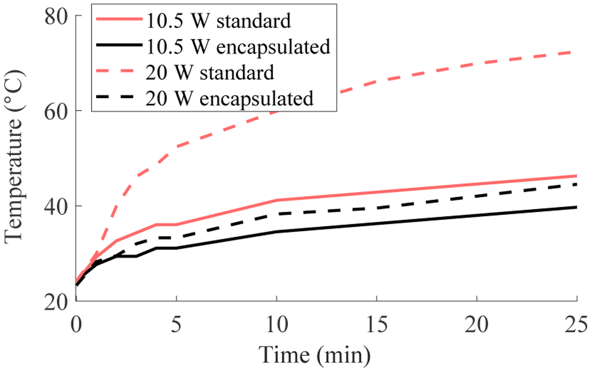
Estimated stator temperatures from (4) based on measured winding resistance during 10.5 W and 20 W power loss experiments (controlled by power supply current). The black lines correspond to the encapsulated motor, and the red lines correspond to the motor without encapsulation (standard).
In addition to encapsulation technology, we designed a heat sink around the stator case to transfer heat from the stator to the environment through fan openings in the front of the outer nylon case (Fig. 1). As described next, the stator/heat sink is separated from the human user by the motor mount, nylon case, and leg attachments, providing multiple layers of insulation to prevent discomfort or harm to the user.
IV. Design of Orthosis System
This section presents the design of the powered knee orthosis (Fig. 1) with the previously presented actuator. In particular, we introduce the details of the mechanical system, electrical system, and torque control system for the orthosis. Two mirrored copies of this design (for left and right legs) are implemented for the human subjects study in Section V.
A. Mechanical System Design
The main body of the orthosis is a 3D-printed nylon mechanical housing, which is secured to the user’s thigh and lower leg by two straps each (Fig. 1). These straps transfer the actuator torques and suspend the device weight (2.69 kg including battery). The device is further suspended through attachments to a utility belt or passive orthosis at the hip. From the actuator output, the shank attachment contains several adjustable linkage components to provide additional degrees of freedom to accommodate differences in user anatomy. These linkages terminate in an end effector that fits the user’s leg like an athletic shin guard. An optional double hinge mechanism between the actuator output and the shank attachment allows for the position of the end effector to conform more properly to the user’s leg while still transferring torque in the sagittal plane. A similar double hinge element is present in [19].
B. Electrical System Design
The motor driver (Gold Solo Twitter, Elmo Motion, Inc.) is fixed in the orthosis housing to control the electric motor. The top of the case has two optional, small fans to cool the actuation system, though they were not used in the experiments. A micro-controller (TMS320F28379D, Texas Instruments, Inc.) implements the control algorithm and collects real-time feedback. A 2800 mAh battery (ProLite X, Thunder Power, Inc.) in a removable nylon case provides power to the actuator and electrical system for at least 2 hours of continuous operation.
The motor driver receives the rotor angle from an incremental encoder (E2 Optical, 4096 CPR, US Digital, Inc.) and communicates this data to the controller through Controller Area Network (CAN bus) protocol. The controller estimates the joint angle based on the rotor angle and transmission ratio. An Inertial Measurement Unit (MPU9250, Sparkfun) is installed in the case for future control methods (e.g., [18], [35]). A custom force-sensing insole is inserted into the user’s shoe to detect ground contact. This insole comprises a forcesensitive resistor (Interlink Electronics, CA) encapsulated in molded silicone. A voltage divider circuit sends an analog force signal to the microcontroller, which uses an on/off threshold for activating the controller. During STS and L&L trials, the sensor reading was bypassed so the controller would stay in stance. In future work, instrumented insoles will use scaling logic to create a tapering effect [36] rather than the current Boolean paradigm.
C. Control System Design
1). Low-Level Control:
The low-level control loop is responsible for controlling the actuator to output the desired torque. An actuator’s torque output T (Nm) is often estimated through the motor’s excitation current I (A) according to
| (5) |
where k denotes the actuator’s torque constant (Nm/A), and the offset T0 (Nm) accounts for the system’s combined losses due to electrical and mechanical inefficiencies. The exoskeleton’s high-level controller uses (5) to determine the reference motor current needed to achieve the desired output torque. The motor driver tracks this reference current using a proportionalintegral (PI) control loop, which was auto-tuned in advance.
The actuator’s torque constant itself depends on the motor’s torque constant, the transmission ratio, and the transmission efficiency. In traditional actuators, the transmission efficiency (and thus the torque constant) tends to vary during dynamic motion, causing inaccurate torque estimates from (5). This error is often compensated using torque sensors for closed-loop torque control [17]. Fortunately, quasi-direct drive actuators tend to have a higher, more constant transmission efficiency [12], [14], [18], resulting in accurate torque estimates from (5). The actuator’s torque constant will be identified in Section V, which will allow the powered orthosis to employ current-based torque control, without the use of a torque sensor.
2). High-Level Control:
The high-level controller determines the assistive torque commands based on encoder, IMU, and foot contact feedback. As a simple case study for design validation, we implemented a quasi-stiffness controller for assisting knee extension during STS, L&L, and stair climbing tasks. This method emulates a virtual torsion spring based on the desired torque-angle slope [37]. We utilized quasi-stiffness control during stance and commanded zero torque during swing to allow free motion. The torque control law is
where θ is the measured knee angle with flexion in the positive direction. The output torque was saturated by software at 20.3 Nm (16.9 Nm for stairs) for the safety of the subjects and the motors in the human subject experiments. The quasi-stiffness K = 0.406 Nm/deg was chosen for STS and L&L tasks to achieve the saturation torque at 50 deg knee flexion. A higher stiffness K = 0.487 Nm/deg was chosen for stairs tasks because of the smaller knee range of motion. Although this controller was implemented for simplicity, future work will implement more advanced, task-invariant controllers (e.g., via energy shaping [18], [36], [38]) to optimally support the different activities of daily life.
V. Experimental Results
This section presents experiments to demonstrate the actuator torque output, thermal properties, backdrivability, and feasibility for human assistance. Benchtop experiments were conducted on a test platform (Fig. 4) comprising the actuator, a rotational torque sensor (TRS605, FUTEK Advanced Sensor Technology, Inc.), and a magnetic brake (351 ELEFLEX, Re Controlli Industriali). The rotational torque sensor measured the actuator’s output torque, and the magnetic brake fixed or loaded the output shaft. Able-bodied human subject experiments (N=3) demonstrated the potential benefit of the device in a bilateral configuration during multiple demanding tasks. A supplemental video is available for download.
Fig. 4.
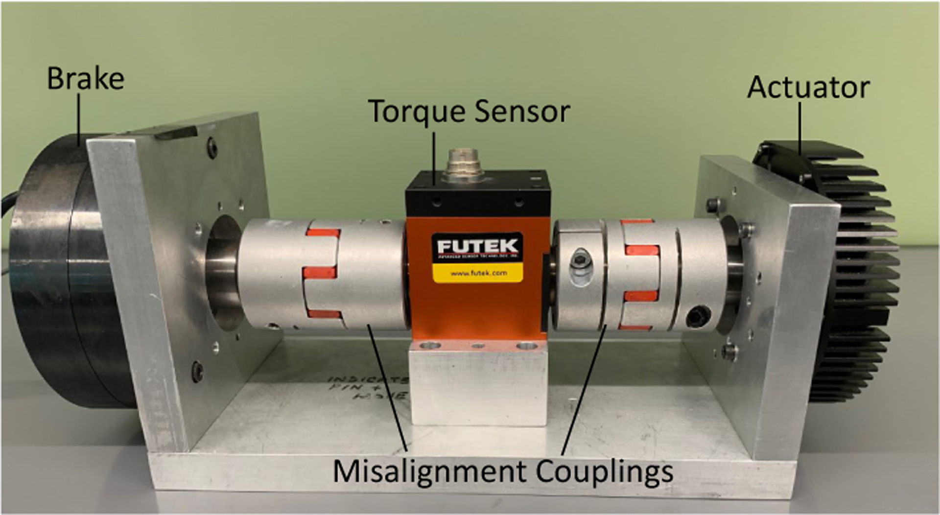
The actuator test platform includes a magnetic brake (left), a FUTEK torque sensor (center), and two misalignment couplings. The actuator (right) is mounted to the testbed frame by its housing, with an output shaft connecting the transmission to the misalignment coupling. The brake is similarly attached.
A. Benchtop Experiments
1). Torque Constant:
We used a series of current step inputs to verify the actuator’s peak torque, torque constant, and offset as defined in (5). Following the procedure in [19], we fixed the actuator’s output shaft, increased the motor’s active current from 0 to 35 A in 5 A increments, and recorded the output at the torque sensor. Fig. 5 shows that the torque output reached 23.9 Nm with a linear relationship to current (0–35 A). A linear fit estimated the torque constant as 0.71 Nm/A with an offset of −0.86 Nm, which can be used to implement current-based torque control. However, we observed the torque constant can vary up to 11% depending on testing conditions.
Fig. 5.
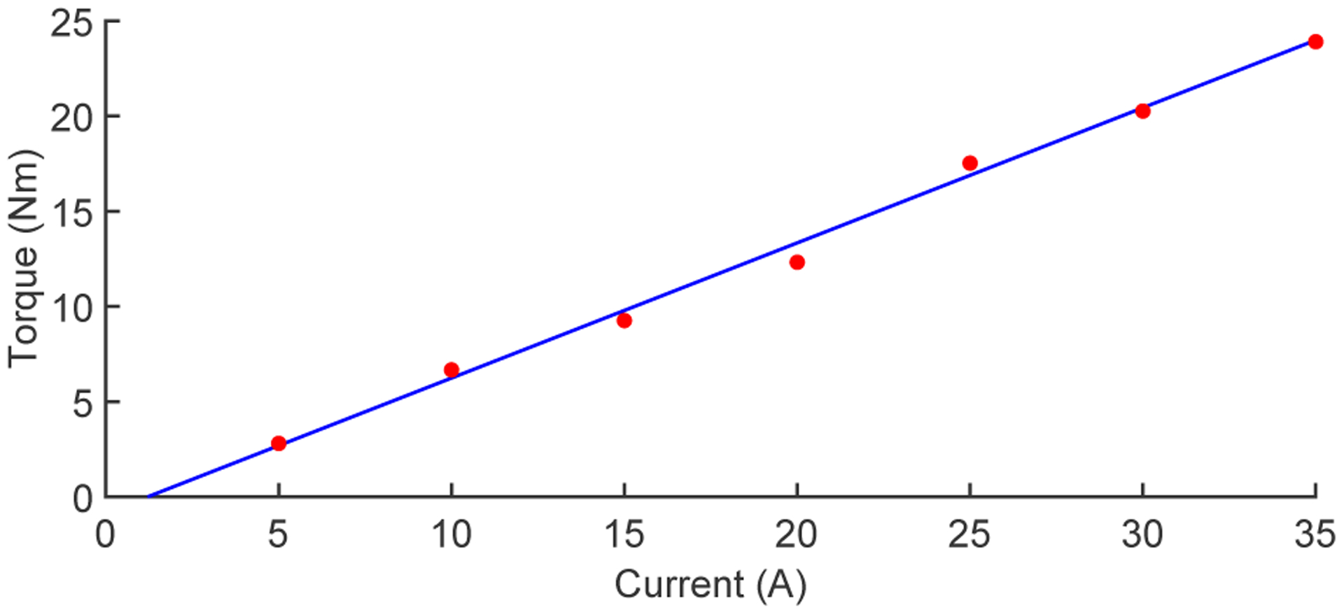
Output torque measured over current inputs (5–35 A) to identify the actuator torque constant and peak torque. Torque constant (0.71 Nm/A) and offset (−0.86 Nm) computed by fitting data (red) with linear regression (blue).
2). Torque Step Response:
A step response test was conducted to assess the actuator’s torque bandwidth. We stepped up the excitation current from 3 A (pre-load) to 30 A and recorded the torque response (Fig. 6) at a sampling rate of 1 kHz (then resampled to 10 kHz via linear interpolation for rise time calculation). The observed rise time was 5.7 ms. Assuming second-order actuator dynamics, this rise time implies a natural frequency of 50.3 Hz, which approximates the torque bandwidth within a factor of 2 [39].
Fig. 6.
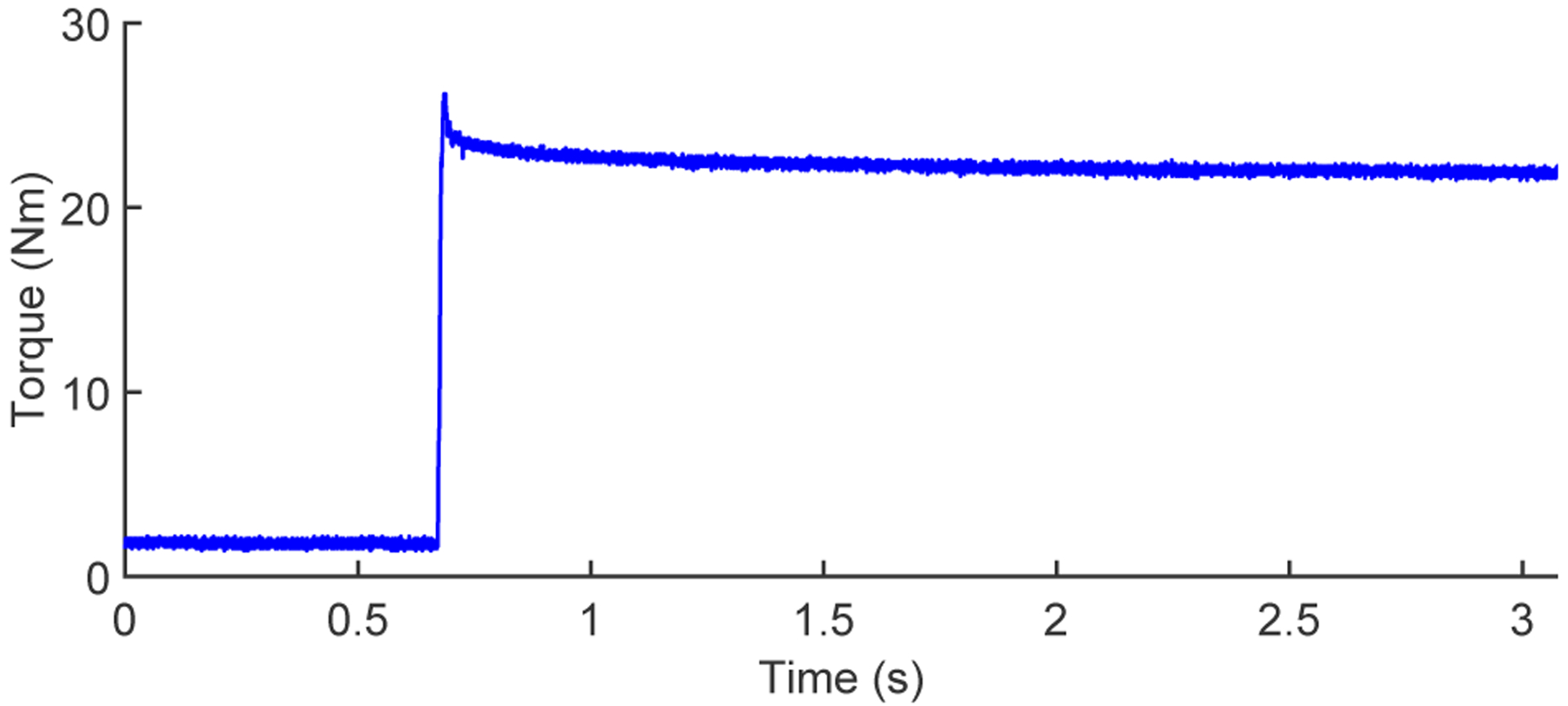
Results from the continuous torque step response test. Torque values shown are from FUTEK torque sensor readings (blue), produced by a current command step function increasing from 3 A to 30 A.
3). Continuous Operating:
The continuous output torque is limited by the motor’s winding temperature, which motivated our use of winding encapsulation with a heat sink. To verify the motor’s temperature at the desired continuous output torque, we applied an excitation of 18 A to the actuator and tuned the magnetic brake torque until the actuator achieved a steady rotational speed less than 100 RPM, similar to the experiment in [15]. We kept the actuator continuously running in this condition for 30 min, using a thermal camera (C2 Compact Thermal Imaging System, FLIR) to measure the stator’s surface temperature at different times (Fig. 7). After 30 min of operation, the motor’s stator surface reached a steady-state temperature of ~80 °C. At steady state we can assume the stator surface temperature is approximately equal to the winding temperature. This temperature is much lower than the winding burn temperature (150 °C). This experiment demonstrates that the actuator can produce a continuous output torque of 12.78 Nm, based on the observed torque constant.
Fig. 7.
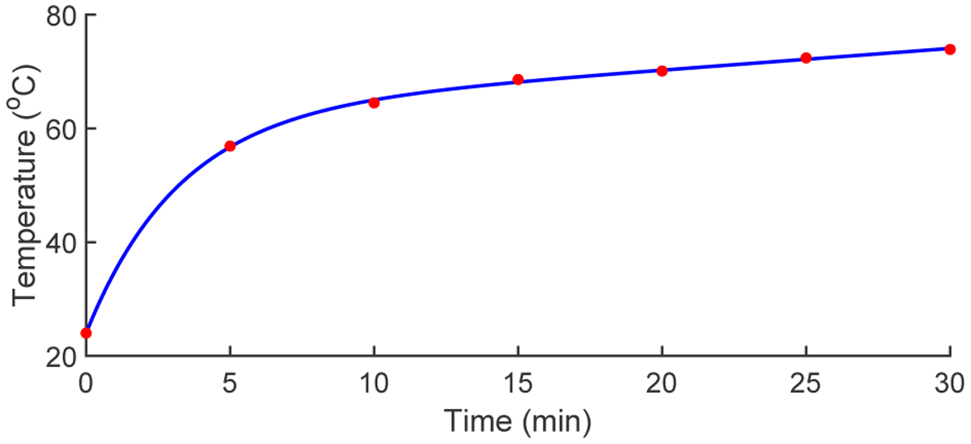
The temperature curve over 30 minutes of continuous motor operation at 18 A. Maximum stator temperature was recorded at five minute intervals (red), and fit with a two term exponential curve (blue).
4). Backdrivability:
To characterize backdrivability during simulated walking, we manually rotated the actuator’s output shaft between ±30° at frequencies of approximately 1 Hz and 2 Hz on the testbed, similar to the manual backdrive tests in [10], [19]. The backdrive torque measured by the torque sensor was processed using a third-order, low-pass Butterworth filter (10 Hz cutoff) to eliminate sensor noise present at such low torques. The backdrive torque and corresponding angle of the output shaft are shown in Fig. 8. We see that backdrive torque is approximately the same for flexion and extension. For the 1 Hz portion, the peak backdrive torque was 1.91 Nm, and the RMS backdrive torque was 0.57 Nm. For the 2 Hz portion, the peak and RMS backdrive torques were 2.67 Nm and 1.48 Nm, respectively. We estimate that about 2% of the measured backdrive torque is due to the inertia of the shaft connecting the torque sensor, which would be eliminated in practice. Note that the backdrive torque required to overcome static friction varies from 1 to 2 Nm.
Fig. 8.
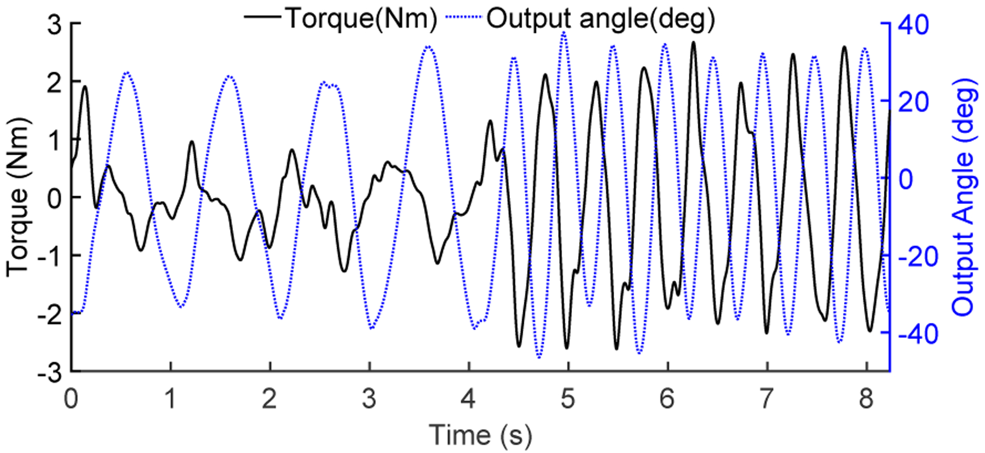
Dynamic backdrive torque. Using the test platform in Fig. 4, the left misalignment coupling was manually deflected in a sinusoidal pattern at approximate frequencies of 1 Hz and 2 Hz. The backdrive torque measured by the FUTEK sensor (solid black, left axis) is plotted against the deflection angle measured by the U.S. Digital encoder (dashed blue, right axis).
B. Human Subject Experiments
1). Methods:
A human subjects study was conducted to validate the presented design during multiple tasks that require significant use of the quadriceps musculature, specifically STS, L&L, stair ascent, and stair descent. Following similar validation studies [10], [19], [37], three healthy human subjects (2 male) with mean age of 31.7 (± 5.1) years were enrolled with approval from the Institutional Review Boards at the University of Michigan and the University of Texas at Dallas. All tasks were repeated with mirrored/symmetric knee orthoses on both legs using quasi-stiffness control (active mode), orthoses powered off (passive mode), and without orthoses (bare mode). These modes were alternated to reduce bias. Ten repetitions were collected with each mode for each task. In stair tasks, a repetition corresponded to one gait cycle.
The STS cycle had 3 phases: 1) stand to sit, 2) sitting, and 3) sit to stand. Each phase lasted 1 s, cued using a metronome set to 60 BPM. The position of the chair was kept fixed, and the foot positions were marked to maintain a consistent STS form. The L&L task consisted of 3 phases performed whilst carrying a 18 lb mass (10 lb for female subject): 1) lowering, 2) squat hold, and 3) lifting. Each phase lasted 1 s, also cued using a 60 BPM metronome. The subjects were instructed to use a consistent squatting technique, and the positions of the feet were marked and kept consistent. A building staircase outside the laboratory was used for the stair tasks. A metronome set at 60 BPM helped the subjects keep a consistent cadence that resembles patient populations and ensures longer muscle loading times to better distinguish the effect of the orthosis.
The controller was designed to deliver knee extension torques to aid the anti-gravity quadriceps muscles (i.e., extensors) during stance in multiple tasks. Thus, we used a wireless Delsys system to acquire EMG data from three quadriceps muscles of both limbs: vastus medialis oblique (VMO), rectus femoris (RF), and vastus lateralis (VL). An inter-electrode distance of 10 mm was used after appropriate skin preparation. All EMG data was sampled at 2000 Hz, demeaned, rectified, and smoothed with a low-pass, zero-lag, second-order Butterworth filter (6 Hz cutoff). EMG data corresponding to each STS and L&L repetition was cropped based on the deflection and return to steady state of the sagittal femur angle (measured by an accelerometer in the EMG sensor). The stair trials were cropped into gait cycles using spikes in the accelerometer data corresponding to heel strike. All data was normalized with respect to the maximum peak of the ensemble averages (across repetitions) of the three modes (bare, passive, active) [40]. This was done for each subject, task, and muscle separately, resulting in signals as a percentage of the maximum voluntary contraction level (%MVC). The peak muscle activation level was extracted from the normalized trials, and these trials were integrated with respect to time to represent muscular effort as %MVC.s. Corresponding values from the left and right limbs were averaged in most cases. We excluded the right VL for STS and stair ascent for the first subject after post-processing revealed movement artefact in the EMG. Similarly for the second subject, the left VMO was removed for all tasks and right VL was removed for stair tasks. In these cases, the effort and peak values of the contralateral side were used.
We additionally measured the acoustic levels of a unilateral orthosis with a decibel meter (PCE-322A, PCE Instruments) while a subject performed 5 repetitions of STS, for passive and active modes. Ambient noise levels were also recorded as the baseline. The recording frequency of the sound meter was 9 Hz, and the meter was positioned 50 cm from subject’s ear (78 cm from the motor) while sitting, and 110 cm above the ground. This position was used to measure sound levels that would be heard by the wearer and other people nearby.
2). Results:
Fig. 9 shows the ensemble average (across repetitions) of EMGs for all muscles, tasks, and orthosis modes for the first subject. The commanded orthosis torques are superimposed according to the right vertical axis. Because the legs are symmetric during STS and L&L, EMGs and torques represent the mean across both limbs. For the stairs tasks, we show the EMGs and torques for the side with no EMG or torque measurement artefacts. Reduced EMG was generally observed during periods of higher torque assistance during active mode. Further, the difference between passive and bare was negligible, which can be attributed to high backdrivability of the actuator. Across-subject mean effort and mean peak EMG are shown for each task in Tables III–VI. Both mean effort and mean peak EMG were considerably lower for the active orthosis mode compared to both bare and passive orthosis modes for all tasks and muscles, except for the RF during stair climbing. Fig. 10 shows subject-wise muscular efforts, demonstrating that s1 and s3 responded better to orthosis assistance than s2 for some muscles and tasks.
Fig. 9.
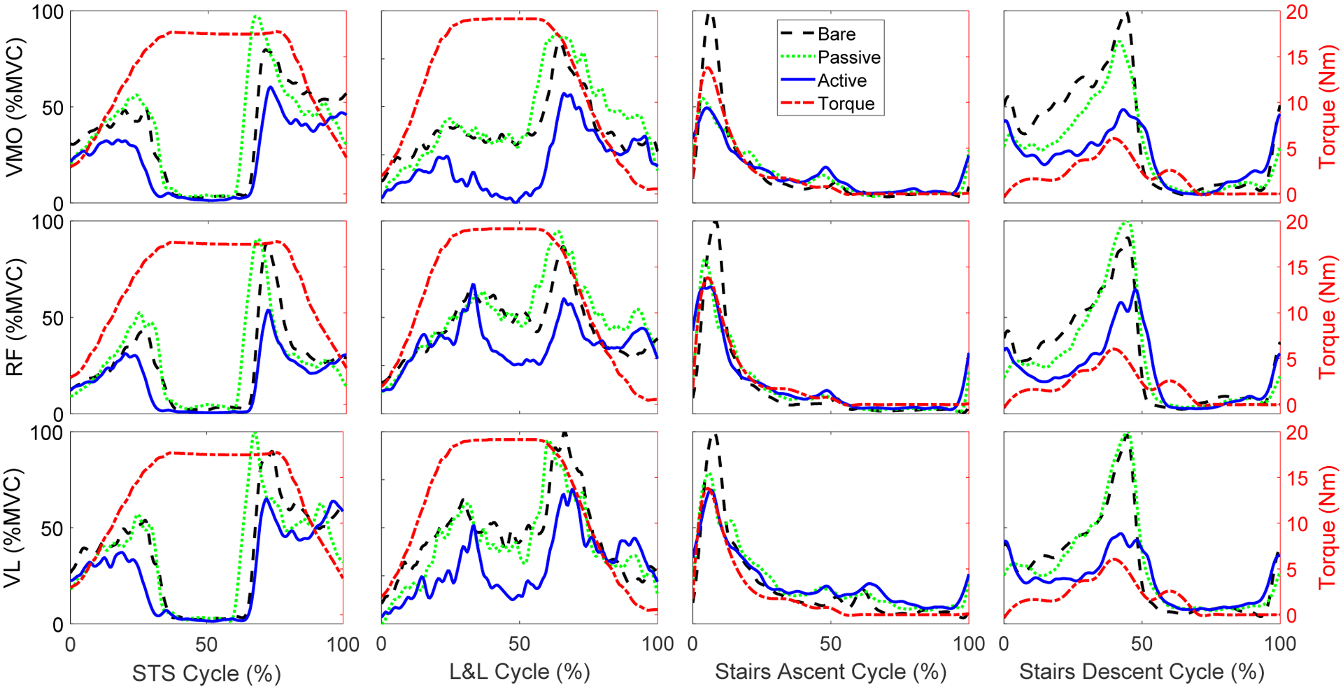
Subject 1 EMG comparisons between bare, passive, and active modes for each muscle (VMO, RF, and VL) and task (STS, L&L, Stairs Ascent, and Stairs Descent). The black dashed (bare), green dotted (passive) and blue solid (active) lines represent the time-normalized ensemble averages across all repetitions. The red dash-dot line represents the mean commanded orthosis torque across all repetitions for the active mode. Torques and EMGs are further averaged over both legs for the symmetric STS and L&L tasks.
TABLE III.
Mean effort (%MVC.s) & peak EMG (%MVC) for STS
| VMO | RF | VL | ||||
|---|---|---|---|---|---|---|
| Effort | Peak | Effort | Peak | Effort | Peak | |
| Active | 70.2 | 80.0 | 67.0 | 96.5 | 74.9 | 93.7 |
| Passive | 105.4 | 105.4 | 93.4 | 114.1 | 101.7 | 121.6 |
| Bare | 112.8 | 109.2 | 92.3 | 117.0 | 97.1 | 115.2 |
TABLE VI.
Mean effort (%MVC.s) & peak EMG (%MVC) for stair descent
| VMO | RF | VL | ||||
|---|---|---|---|---|---|---|
| Effort | Peak | Effort | Peak | Effort | Peak | |
| Active | 57.6 | 94.3 | 56.1 | 101.2 | 41.8 | 75.2 |
| Passive | 62.7 | 107.4 | 62.7 | 113.2 | 48.5 | 92.4 |
| Bare | 64.0 | 105.4 | 58.5 | 97.1 | 57.3 | 103.3 |
Fig. 10.
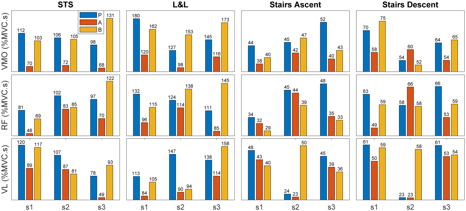
Individual subject comparisons of mean effort across repetitions. Effort is compared between passive (P), active (A), and bare (B) modes for each muscle pair (VMO, RF, and VL) and task (STS, L&L, Stairs Ascent, and Stairs Descent). The average of both legs is reported for each muscle pair.
Finally, sound levels near the orthosis (in active or passive mode) were nearly identical to ambient levels. The mean (SD) values were 44.6 (0.3) dB for ambient, 44.7 (0.6) dB for passive mode, and 44.5 (0.3) dB for active mode.
VI. Discussion
1). Design Implications:
Our actuator design philosophy is tailored to the different requirements of patients with musculoskeletal disorders. We improved backdrivability and torque density using a larger diameter, torque-dense motor with encapsulation technology. This motor allowed the use of a very low-ratio transmission (7:1), built directly inside the stator for a high package factor. The actuator exhibited ~2 Nm peak backdrive torque during walking motions, providing a low mechanical impedance interface between the exoskeleton and the user. As a result, the user can freely move their joint.
To demonstrate the contribution of this design, Table VII compares it with 10 different lower-limb exoskeletons from the literature. In this table, we calculate each actuator’s continuous torque output based on the selected motor’s rated torque and the stated transmission ratio, assuming an ideal transmission efficiency. Motor specifications were obtained from vendor data sheets, using newer versions when available, so some values are better than the originally published results. To our knowledge, their stators have nylon insulation layers rather than encapsulation. The theoretical backdrive torque is calculated by the motor’s rotor inertia and transmission ratio, assuming a typical acceleration rate of 17 rad/s2 for a lower-limb joint during level-ground walking [45]. This theoretical analysis neglects friction and cogging because those properties are rarely reported. Finally, backdrivability is calculated as the ratio between the actuator’s continuous torque output and its theoretical backdrive torque. A few backdrivable exoskeletons (e.g., [19], [46]) are not included in this comparison because their motor selections or specifications were not reported.
TABLE VII.
Comparison of Lower-Limb Exoskeletons / Orthoses
| Exoskeleton | Motor Inertia (kg-cm2) | Motor Rated Torque (Nm) | Gear Ratio | Actuator Rated Torque (Nm) | Reflected Inertia (kg-cm2) | Backdrive Torque (Nm) | Backdrivability |
|---|---|---|---|---|---|---|---|
| Presented Knee Orthosis | 4.1 | 1.82 | 7 | 12.78 | 200.9 | 0.34 | 35.58 |
| UTD Knee-Ankle Orthosis [17] | 1.2 | 1.25 | 24 | 30 | 691.5 | 1.19 | 25.04 |
| CRSA Knee Orthosis [41] | 0.139 | 0.192 | 150 | 28.8 | 3127.5 | 5.4 | 5.33 |
| UC Knee Orthosis [9] | 0.139 | 0.192 | 60 | 11.52 | 500.4 | 0.86 | 13.39 |
| Vanderbilt Exoskeleton [1] | 3.17 | 0.953 | 24 | 22.87 | 1825.92 | 3.16 | 7.23 |
| Vrije Exoskeleton [42] | 0.135 | 0.144 | 188 | 27.07 | 4771.44 | 8.26 | 3.27 |
| GEMS Hip Orthosis [23] | 0.135 | 0.144 | 50 | 7.2 | 337.5 | 0.58 | 12.41 |
| NCSU Exoskeleton [43] | 3.17 | 0.953 | 100 | 95.3 | 31700 | 54.93 | 1.73 |
| AGoRA Exoskeleton [44] | 0.853 | 0.577 | 160 | 92.32 | 21376 | 37.04 | 2.49 |
Some designs in Table VII, e.g., the NCSU and AGoRA exoskeletons, use a very high transmission ratio to produce high torque output for supporting users with minimal limb function. The reflected inertia of these devices is 31,700 kg-cm2 and 21,376 kg-cm2, respectively. For the assumed joint acceleration, their theoretical backdrive torques are very high: 54.93 Nm and 37.04 Nm, respectively. Even with an extremely low-inertia motor, e.g., Vrijie and CRSA, the reflected inertia still reaches 4,771 kg-cm2 and 3,128 kg-cm2, respectively. On the other hand, the UC Berkeley knee orthosis and GEMS hip orthosis successfully reduce the reflected inertia to 500.4 kg-cm2 and 337.5 kg-cm2, respectively, but with relatively low output torque (11.52 Nm and 7.2 Nm, respectively). Inspired by the Vanderbilt exoskeleton, our previously designed knee-ankle orthosis, named ComEx 1, uses a high-torque motor with a 24:1 transmission to produce 30 Nm continuous torque output. ComEx 1 has a reflected inertia of 691.5 kg-cm2 and theoretical backdrive torque of 1.19 Nm, resulting in high backdrivability. The presented knee orthosis, ComEx 2, has a reflected inertia of only 201 kg-cm2 with theoretical backdrive torque of 0.34 Nm. Because this backdrive analysis neglects friction and cogging and considers a smaller acceleration than our experiments, this theoretical value is smaller than the measured backdrive torque (~2 Nm) in Section V. Given the 12.78 Nm continuous output torque, ComEx 2 has the highest backdrivability in our comparison. Because its low-ratio transmission has fewer/slower meshing parts, it also produces far less acoustic noise than state-of-art exoskeletons with high-ratio transmissions. Direct comparisons could not be made because acoustic noise is rarely reported in the literature.
The main limitation of our design approach is the larger motor mass and lower torque density according to (3). Quasi-direct drives tend to be heavier than actuators with lightweight, high-speed motors and high-ratio harmonic gears, for example. Therefore, if the end user cares more about weight than backdrivability, our approach may not be ideal. However, our second and third design principles offer ways to improve torque density, so that backdrivability can be optimized with only a small tradeoff in mass. Our thermal results indicate that the motor heat sink was overdesigned and could be reduced for weight savings. We also believe it is possible to further reduce mass using emerging light-weight, high-torque motor architectures such as the T-motor U8 [20], [21].
2). Biomechanical Implications:
By leveraging its backdrivability, ComEx 2 delivered effective partial assistance using direct current control, whereas the passive (unpowered) mode had a negligible effect on muscular effort compared to bare mode. The mean ensemble average plots of the best responding subject in Fig. 9 show that the assistance torques were generally well aligned (in harmony) with the quadriceps muscle activation profiles in all tasks. Additionally, muscular activation was generally lower for active mode compared to bare and passive modes for all tasks. Tables III–VI show that, with the exception of the RF in stair ascent/descent, the mean effort and mean peak EMG were lower with orthosis assistance than without it. The RF is a biarticular muscle, suggesting that hip assistance may be needed to further reduce its activation.
The reduction in peak muscular activation motivates future applications to knee OA, where pain in the patello-femoral joint is related to quadriceps force [5]. By reducing peak muscle activation/force, patients may be able to perform demanding tasks such as STS and stair climbing with less pain. Importantly, this encourages a more active lifestyle, which is recommended for controlling the progression of knee OA [47]. On the other hand, the demonstrated reduction in quadriceps effort is beneficial in the context of movement augmentation. For example, assisting the quadriceps may encourage and prolong the use of the recommended squat technique in workplace L&L tasks known to cause LBP [7].
The reductions in muscle activation (both peak and effort) with assistance were marginal for stair tasks compared to STS and L&L. Stair descent has two phases of higher muscle activity (Fig. 9) during 1) early stance for stabilization and impact absorption, and 2) mid-to-late stance when the quadriceps are actively involved in lowering the body mass. However, the controller only effectively assisted the second phase, because the virtual torsion spring provides little torque when the knee flexion angle is small. Hence, a controller that better aids impact absorption by considering joint velocity (e.g., [38]) may further reduce muscle effort for more dynamic tasks like stair climbing. Additionally, a swing-phase controller could reduce associated muscle activation that contributed to higher effort levels with the orthoses for some subjects/muscles during stair tasks (Fig. 10).
Finally, we note that our subjects had minimal (s1) or no prior experience (s2, s3) with ComEx 2. The human subjects outcomes may improve by providing more acclimation time. Some muscles of s2 were less responsive to orthosis assistance compared to s1 and s3, especially during stair descent (Fig. 10). Additional practice may yield more holistic benefit by reducing hesitation and the associated co-contraction [48], especially during more challenging tasks like stair climbing.
VII. Conclusion and Future Work
The presented orthosis followed design principles to 1) improve backdrivability by increasing the motor diameter, 2) increase torque density by improving the thermal environment, and 3) increase torque density by improving package factor. The resulting orthosis produced strong assistance torque, exhibited low backdrive torque, and was lightweight with low complexity. This orthosis exhibited higher backdrivability than previous designs in the literature. Barring the RF during stair climbing, bilateral orthosis assistance (active mode) facilitated reductions in mean quadriceps effort as well as mean peak muscular activation in all tasks when compared to bare and passive modes. Finally, the quasi-direct drive actuator produced negligible sound levels compared to ambient noise, which will make this technology more acceptable for daily use than state-of-art designs using louder, high-ratio transmissions.
Future work will implement a task-invariant control strategy with energetic rather than kinematic objectives [18], [36], [38] to facilitate multiple activities of daily living. We also aim for this control method to facilitate impact absorption during early stance in tasks such as stairs descent and walking to provide more holistic quadriceps assistance. Finally, this system will be validated in broad populations, such as mitigating joint pain in knee OA, facilitating the use of the biomechanically sound squat technique during L&L tasks, and assisting activities of daily living in individuals with age-related immobility.
Supplementary Material
TABLE IV.
Mean effort (%MVC.s) & peak EMG (%MVC) for L&L
| VMO | RF | VL | ||||
|---|---|---|---|---|---|---|
| Effort | Peak | Effort | Peak | Effort | Peak | |
| Active | 111.3 | 85.9 | 98.3 | 85.0 | 96.1 | 89.3 |
| Passive | 150.7 | 107.7 | 122.0 | 98.3 | 132.6 | 102.8 |
| Bare | 163.1 | 121.5 | 132.6 | 112.6 | 119.2 | 93.5 |
TABLE V.
Mean effort (%MVC.s) & peak EMG (%MVC) for stair ascent
| VMO | RF | VL | ||||
|---|---|---|---|---|---|---|
| Effort | Peak | Effort | Peak | Effort | Peak | |
| Active | 39.9 | 99.2 | 37.0 | 113.8 | 34.9 | 85.5 |
| Passive | 47.2 | 109.6 | 42.5 | 118.1 | 39.0 | 92.5 |
| Bare | 43.2 | 111.9 | 33.9 | 99.3 | 42.1 | 111.3 |
Acknowledgments and Competing Interests
The authors thank Calvin Stence, Jack Doan, M. Taha Ahmad, Kayla Shepodd, and Vincent Huang for their assistance. Hanqi Zhu is co-founder and shareholder in Enhanced Power. These research results may be related to the business interests of Enhanced Power. The terms of this arrangement have been reviewed and approved by the University of Texas at Dallas in accordance with its policy on objectivity in research.
This work was supported by the National Institute of Child Health & Human Development of the NIH under Award Number DP2HD080349 and the National Science Foundation under Award 1652514 / 1949869. The content is solely the responsibility of the authors and does not necessarily represent the official views of the NIH or the NSF. This work was also supported by a gift from The Philip R. Jonsson Foundation. R. D. Gregg holds a Career Award at the Scientific Interface from the Burroughs Wellcome Fund. The work of Hanqi Zhu was supported by the Eugene McDermott Graduate Fellowship.
Biographies

Hanqi Zhu earned the B.S. (2011) and M.S. (2013) degrees in mechanical engineering from the Xi’an Jiaotong University and the Ph.D. (2020) in electrical engineering from the University of Texas at Dallas. He currently works for Enhanced Power. His research concerns advanced mechatronics systems with applications in wearable rehabilitation robots.

Chris Nesler received his B.S. in Mechanical Engineering from Oregon State University in 2014, and his M.S. in Biomedical Engineering from Northwestern University in 2016. He now works as a Research Engineer at the Locomotor Control Systems Laboratory (University of Michigan, formerly University of Texas at Dallas), where he works on design and improvement of various powered lower-limb prostheses and exoskeletons.

Nikhil Divekar received the B.S. and M.S. degrees in mechatronics and biomedical engineering from the University of Cape Town (UCT), in 2008 and 2013, respectively. He is currently pursuing the Ph.D. degree in Robotics at the University of Michigan. Previously he was a Ph.D. student at The University of Texas at Dallas and a Research Officer with the Department of Exercise Science and Sports Medicine at the University of Cape Town. His research concerns the neurophysiological basis of rehabilitation and its application to wearable robots.

Vamsi Peddinti received his B.S in Electronics and Computer Engineering from GITAM University, and his M.S in Electrical and Electronics Engineering from Indiana University Purdue University Indianapolis (IUPUI). He now works as a Research Engineer at Locomotor Control Systems Laboratory (University of Michigan, formerly at University of Texas at Dallas) where he works on electronic hardware and software development of various powered lower-limb prostheses and exoskeletons.

Robert D. Gregg (S’08-M’10-SM’16) received the B.S. degree in electrical engineering and computer sciences from the University of California at Berkeley in 2006, and the M.S. and Ph.D. degrees in electrical and computer engineering from the University of Illinois at Urbana-Champaign in 2007 and 2010, respectively. He joined the Department of Electrical Engineering and Computer Science and the Robotics Institute, University of Michigan, as an Associate Professor in 2019. He was previously an Assistant Professor at The University of Texas at Dallas. His research concerns the control of bipedal locomotion and wearable robots.
References
- [1].Farris R, Quintero H, and Goldfarb M, “Preliminary evaluation of a powered lower limb orthosis to aid walking in paraplegic individuals,” IEEE Trans. Neural Syst. Rehabil. Eng, vol. 19, no. 6, 2011. [DOI] [PMC free article] [PubMed] [Google Scholar]
- [2].Murray SA, Ha KH, Hartigan C, and Goldfarb M, “An assistive control approach for a lower-limb exoskeleton to facilitate recovery of walking following stroke,” IEEE Trans. Neural Syst. Rehabil. Eng, vol. 23, no. 3, pp. 441–449, 2015. [DOI] [PubMed] [Google Scholar]
- [3].“Mobility is Most Common Disability Among Older Americans, Census Bureau Reports,” 2014. [Online]. Available: http://www.census.gov/newsroom/press-releases/2014/cb14-218.html.
- [4].United States Bone and Joint Initiative, The Burden of Musculoskeletal Diseases in the United States, 3rd ed., 2014. [Online]. Available: http://www.boneandjointburden.org/ [Google Scholar]
- [5].Amin S, Baker K, Niu J, Clancy M, Goggins J, Guermazi A, Grigoryan M, Hunter DJ, and Felson DT, “Quadriceps strength and the risk of cartilage loss and symptom progression in knee osteoarthritis,” Arthritis and Rheumatism, 2009. [DOI] [PMC free article] [PubMed] [Google Scholar]
- [6].Alnahdi AH, Zeni JA, and Snyder-Mackler L, “Muscle Impairments in Patients With Knee Osteoarthritis,” Sports Health, 2012. [DOI] [PMC free article] [PubMed] [Google Scholar]
- [7].Hsiang SM, Brogmus GE, and Courtney TK, “Low back pain (LBP) and lifting technique–A review,” International Journal of Industrial Ergonomics, vol. 4, no. 19, pp. 59–74, 1997. [Google Scholar]
- [8].Kaminaga H, Amari T, Niwa Y, and Nakamura Y, “Development of knee power assist using backdrivable electro-hydrostatic actuator,” in IEEE/RSJ Int. Conf. Intelli. Robots & Systems, 2010, pp. 5517–5524. [Google Scholar]
- [9].Kong K, Bae J, and Tomizuka M, “Control of rotary series elastic actuator for ideal force-mode actuation in human–robot interaction applications,” IEEE/ASME Trans. Mechatronics, vol. 14, no. 1, 2009. [Google Scholar]
- [10].Shepherd MK and Rouse EJ, “Design and validation of a torque controllable knee exoskeleton for sit-to-stand assistance,” IEEE/ASME Trans. Mechatronics, vol. 22, no. 4, pp. 1695–1704, 2017. [Google Scholar]
- [11].Seok S, Wang A, Otten D, and Kim S, “Actuator design for high force proprioceptive control in fast legged locomotion,” in IEEE/RSJ Int. Conf. Intelli. Robots & Systems, 2012, pp. 1970–1975. [Google Scholar]
- [12].Seok S, Wang A, Chuah MYM, Hyun DJ, Lee J, Otten DM, Lang JH, and Kim S, “Design principles for energy-efficient legged locomotion and implementation on the MIT Cheetah robot,” IEEE/ASME Trans. Mechatron, vol. 20, no. 3, pp. 1117–1129, 2015. [Google Scholar]
- [13].Ding Y and Park H-W, “Design and experimental implementation of a quasi-direct-drive leg for optimized jumping,” in IEEE/RSJ Int. Conf. Intelligent Robots & Systems, 2017. [Google Scholar]
- [14].Elery T, Rezazadeh S, Nesler C, and Gregg RD, “Design and validation of a powered knee-ankle prosthesis with high-torque, low-impedance actuators,” in IEEE Trans. Robotics, 2020. [DOI] [PMC free article] [PubMed] [Google Scholar]
- [15].Paine N and Sentis L, “Design and comparative analysis of a retrofitted liquid cooling system for high-power actuators,” in Actuators, vol. 4, no. 3. MDPI, 2015, pp. 182–202. [Google Scholar]
- [16].Zhu T, Hooks J, and Hong D, “Design, modeling, and analysis of a liquid cooled proprioceptive actuator for legged robots,” in IEEE/ASME Int. Conf. Advanced Intelligent Mechatronics, 2019, pp. 36–43. [Google Scholar]
- [17].Zhu H, Doan J, Stence C, Lv G, Elery T, and Gregg R, “Design and validation of a torque dense, highly backdrivable powered knee-ankle orthosis,” in IEEE Int. Conf. Robot. Autom, 2017, pp. 504–510. [DOI] [PMC free article] [PubMed] [Google Scholar]
- [18].Lv G, Zhu H, and Gregg RD, “On the design and control of highly backdrivable lower-limb exoskeletons,” IEEE Control Systems Magazine, vol. 38, no. 6, pp. 88–113, 2018. [DOI] [PMC free article] [PubMed] [Google Scholar]
- [19].Wang J, Li X, Huang T, Yu S, Li Y, Chen T, Carriero A, Oh-Park M, and Su H, “Comfort-centered design of a lightweight and backdrivable knee exoskeleton,” IEEE Robot. Autom. Lett, vol. 3, no. 4, 2018. [Google Scholar]
- [20].Katz B, Di Carlo J, and Kim S, “Mini cheetah: A platform for pushing the limits of dynamic quadruped control,” in IEEE Int. Conf. Robot. Autom, 2019, pp. 6295–6301. [Google Scholar]
- [21].“T-Motor A80–6,” 2020. [Online]. Available: http://store-en.tmotor.com/goods.php?id=894
- [22].Zhu H, Nesler C, Divekar N, Ahmad MT, and Gregg RD, “Design and validation of a partial-assist knee orthosis with compact, backdrivable actuation,” in IEEE Int. Conf. Rehabil. Robot, 2019. [DOI] [PMC free article] [PubMed] [Google Scholar]
- [23].Lee Y, Roh S.-g., Lee M, Choi B, Lee J, Kim J, Choi H, Shim Y, and Kim Y-J, “A flexible exoskeleton for hip assistance,” in IEEE/RSJ Int. Conf. Intelli. Robots & Systems, 2017, pp. 1058–1063. [Google Scholar]
- [24].Laschowski B, McPhee J, and Andrysek J, “Lower-limb prostheses and exoskeletons with energy regeneration: Mechatronic design and optimization review,” J. Mechanisms and Robotics, vol. 11, no. 4, 2019. [Google Scholar]
- [25].Li H, Klontz KW, Ferrell VE, and Barber D, “Thermal models and electrical machine performance improvement using encapsulation material,” IEEE Trans. Ind. Appl, vol. 53, no. 2, pp. 1063–1069, 2017. [Google Scholar]
- [26].Sensinger JW, Clark SD, and Schorsch JF, “Exterior vs. interior rotors in robotic brushless motors,” in IEEE Int. Conf. Robot. Autom, 2011, pp. 2764–2770. [Google Scholar]
- [27].Sensinger JW and Lipsey JH, “Cycloid vs. harmonic drives for use in high ratio, single stage robotic transmissions,” in IEEE Int. Conf. Robot. Autom, 2012, pp. 4130–4135. [Google Scholar]
- [28].Astephen JL, Deluzio KJ, Caldwell GE, and Dunbar MJ, “Biomechanical changes at the hip, knee, and ankle joints during gait are associated with knee osteoarthritis severity,” Journal of Orthopaedic Research, vol. 26, no. 3, pp. 332–341, 2008. [DOI] [PubMed] [Google Scholar]
- [29].Antwi-Afari M, Li H, Edwards D, Prn E, Seo J, and Wong A, “Biomechanical analysis of risk factors for work-related musculoskeletal disorders during repetitive lifting task in construction workers,” Automation in Construction, vol. 83, pp. 41–47, 2017. [Google Scholar]
- [30].Neder JA, Nery LE, Shinzato GT, Andrade MS, Peres C, and Silva AC, “Reference values for concentric knee isokinetic strength and power in nonathletic men and women from 20 to 80 years old,” J. Orthop. Sport Phys, vol. 29, no. 2, pp. 116–126, 1999. [DOI] [PubMed] [Google Scholar]
- [31].Sullivan CR and Sanders SR, “Models for induction machines with magnetic saturation of the main flux path,” in IEEE Industry Applications Society Annual Meeting, 1992, pp. 123–131. [Google Scholar]
- [32].Kelleher WP and Kondoleon AS, “A magnetic bearing suspension system for high temperature gas turbine applications: Part iii–magnetic actuator development,” in ASME Int. Gas Turbine and Aeroengine Congress and Exhibition, 1997, p. V004T14A030. [Google Scholar]
- [33].El-Refaie AM, “Fractional-slot concentrated-windings synchronous permanent magnet machines: Opportunities and challenges,” IEEE Trans. Industrial Electronics, vol. 57, no. 1, pp. 107–121, 2010. [Google Scholar]
- [34].Molian S, Mechanism design: an introductory text. Cambridge University Press, 1982. [Google Scholar]
- [35].Lv G and Gregg RD, “Underactuated potential energy shaping with contact constraints: Application to a powered knee-ankle orthosis,” IEEE Trans. Control Syst. Technol, vol. 26, no. 1, pp. 181–193, 2018. [DOI] [PMC free article] [PubMed] [Google Scholar]
- [36].Divekar NV, Lin J, Nesler C, Borboa S, and Gregg RD, “A potential energy shaping controller with ground reaction force feedback for a multi-activity knee-ankle exoskeleton,” in IEEE Int. Conf. Biomedical Robotics Biomechatronics, 2020. [Google Scholar]
- [37].Shamaei K, Cenciarini M, Adams A, Gregorczyk K, Schiffman J, and Dollar A, “Design and evaluation of a quasi-passive knee exoskeleton for investigation of motor adaptation in lower extremity joints,” IEEE Trans. Biomed. Eng, vol. 61, no. 6, pp. 1809–1821, 2014. [DOI] [PubMed] [Google Scholar]
- [38].Lin J, Divekar NV, Lv G, and Gregg RD, “Optimal task-invariant energetic control for a knee-ankle exoskeleton,” IEEE Control Systems Letters, 2020. [Google Scholar]
- [39].Franklin GF, Powell JD, and Emami-Naeini A, Feedback Control of Dynamic Systems, 7th ed. New York, NY: Pearson, 2014. [Google Scholar]
- [40].Yang J and Winter D, “Electromyographic amplitude normalization methods: improving their sensitivity as diagnostic tools in gait analysis,” Arch. Phys. Med. Rehabil, vol. 65, no. 9, p. 517521, 1984. [PubMed] [Google Scholar]
- [41].Liu L, Leonhardt S, and Misgeld BJE, “Experimental validation of a torque-controlled variable stiffness actuator tuned by gain scheduling,” IEEE/ASME Trans. Mechatronics, vol. 23, no. 5, pp. 2109–2120, 2018. [Google Scholar]
- [42].Beyl P, Van Damme M, Van Ham R, Versluys R, Vanderborght B, and Lefeber D, “An exoskeleton for gait rehabilitation: prototype design and control principle,” in IEEE Int. Conf. Robot. Autom, 2008. [Google Scholar]
- [43].Zhang T, Tran M, and Huang H, “Design and experimental verification of hip exoskeleton with balance capacities for walking assistance,” IEEE/ASME Trans. Mechatronics, vol. 23, no. 1, pp. 274–285, February 2018. [Google Scholar]
- [44].Snchez-Manchola M, Gmez-Vargas D, Casas-Bocanegra D, Mnera M, and Cifuentes CA, “Development of a robotic lower-limb exoskeleton for gait rehabilitation: Agora exoskeleton,” in IEEE ANDESCON, 2018. [Google Scholar]
- [45].Winter DA, Biomechanics and Motor Control of Human Movement, 2nd ed. New York, NY: Wiley, 2009. [Google Scholar]
- [46].Brackx B, Geeroms J, Vantilt J, Grosu V, Junius K, Cuypers H, Vanderborght B, and Lefeber D, “Design of a modular add-on compliant actuator to convert an orthosis into an assistive exoskeleton,” in IEEE Int. Conf. Biomed. Robot. Biomechatron, 2014, pp. 485–490. [Google Scholar]
- [47].Dunlop DD, Semanik P, Song J, Sharma L, Nevitt M, Jackson R, Mysiw J, Chang RW, Investigators OI et al. , “Moving to maintain function in knee osteoarthritis: evidence from the osteoarthritis initiative,” Arch. Phys. Med. Rehabil, vol. 91, no. 5, pp. 714–721, 2010. [DOI] [PMC free article] [PubMed] [Google Scholar]
- [48].Larsen AH, Puggaard L, Hämäläinen U, and Aagaard P, “Comparison of ground reaction forces and antagonist muscle coactivation during stair walking with ageing,” Journal of Electromyography and Kinesiology, vol. 18, no. 4, pp. 568–580, 2008. [DOI] [PubMed] [Google Scholar]
Associated Data
This section collects any data citations, data availability statements, or supplementary materials included in this article.