

Summary
A catalyst based on Pd on glass wool (Pd@GW) shows exceptional performance and durability for the reduction of nitrobenzene to aniline at room temperature and ambient pressure in aqueous solutions. The reaction is performed in a flow system and completed with 100% conversion under a variety of flow rates, 2 to 100 mLmin−1 (normal laboratory fast flow conditions). Sodium borohydride or dihydrogen perform well as reducing agents. Scale-up of the reaction to flows of 100 mLmin−1 also shows high conversions and robust catalytic performance. Catalyst deactivation can be readily corrected by flowing a NaBH4 solution. The catalytic system proves to be generally efficient, performing well with a range of nitroaromatic compounds. The shelf life of the catalyst is excellent and its reusability after 6-8 months of storage showed the same performance as for the fresh catalyst.
Subject areas: Chemistry, Catalysis, Green chemistry, Engineering
Graphical abstract
Highlights
-
•
Palladium on glass wool catalyzes reduction of nitrobenzene to aniline
-
•
Catalytic flow process at atmospheric temperature and pressure in aqueous media
-
•
Facile catalyst synthesis using inexpensive glass wool and low palladium loading
-
•
Sustainable chemical process using sodium borohydride or hydrogen gas
Chemistry; Catalysis; Green chemistry; Engineering
Introduction
The reduction of nitro compounds to the corresponding amines is important in the fine chemicals and pharmaceutical industries (Colom et al., 2002; Fieser, 1941; Orlandi et al., 2018). Among the many nitro compound reductions, no one compares with the conversion of nitrobenzene to aniline, responsible for over 95% of the use of nitrobenzene; in 2019 a total of 1.63 million metric tons of nitrobenzene were produced in the USA and its annual worldwide sales are rapidly approaching $10B (Global Industry Analysts, 2021). In turn, 80% of the aniline is used to produce methylene diphenyl diisocyanate (MDI), a key material in the production of polyurethanes (Amini and Lowenkron, 2003).
The reduction of nitrobenzene to aniline was first observed in 1843, eventually leading to the Beauchamp process (1854) using iron and hydrochloric acid (Ullmann and Bohnet, 2009), but ultimately replaced by efficient catalytic processes employed by many of the key current producers (Goszewska et al., 2017). In one research, nano-Fe3O4@Al2O3 catalyst was used in a flow system at 150°C and 30 bar back pressure (Moghaddam et al., 2014). There are numerous patents and reports on the subject (Gholinejad et al., 2019; Feng et al., 2016), one in particular, uses 5 wt% palladium on carbon and operates at temperatures and pressures as high as 225°C and 5,000 kPa, respectively (Cossaboon, 1980). Three decades later, patents still include palladium as a catalyst and work at temperatures of 200°C and pressures of 600 kPa (Hassan et al., 2012).
Moving forward, more sustainable processes should be developed for the reduction of nitro compounds, including some of the following advances: (i) reaction conditions close to ambient temperatures and pressures, reducing production cost and improving safety, (ii) use of green solvents, such as water; and (iii) operate under flow conditions with easy-to-prepare catalysts. A recent review deals specifically with point (ii) including some examples of flow systems (Formenti et al., 2019). Other flow compatible reactions, such as Suzuki-Miyaura coupling on Pd catalysts, have been also reported; however, high loadings of Pd (up to 7 wt%) are necessary (Yamada et al., 2020; Ichitsuka et al., 2019).
In this contribution, we report on the catalytic reduction of nitro compounds (illustrated for nitrobenzene in Scheme 1) working at ambient temperature and pressures in aqueous solution, using a reusable catalyst based on palladium supported on glass wool (Pd@GW), and operating under flow conditions. This follows the successful development of inexpensive glass wool as a catalyst support (Elhage et al., 2018; Teixeira et al., 2020). Although non-precious metals could be used in the reduction of nitro compounds, our previous results suggest that, in contrast with Pd, non-noble metals such as Cu or Co have a weak attachment to the treated glass wool support and some metal leaching cannot be easily avoided. Thus, this work achieves all the goals indicated above utilizing a recyclable catalytic system, thereby reducing the amount of noble metal used. In addition, the use of NaBH4 as an easy-to-handle, non-explosive and non-flammable reducing agent facilitates screening of catalytic conditions, whereas H2 at atmospheric pressure is highly efficient at avoiding the common need for high pressures and specialized reactors. Finally, we also report a successful attempt to scale up the process, from an initial milligram scale to multigram product formation and the handling of multi-litre volumes.
Scheme 1.

Reduction of nitrobenzene using Pd@GW in a flow system
Experimental procedures
A few preliminary batch experiments were performed in glass containers (25 mL) under gentle stirring, as strong stirring can damage the glass wool fibers. Most of the work was performed in glass tubes (borosilicate) of various diameters and lengths. The catalysts were prepared in situ in the same tubes where they would be used for catalytic nitro reduction. The solvent is water or aqueous ethanol for all the experiments described here and the maximum concentration used was 0.1 M. Small amount of ethanol was used to facilitate solubilization at higher concentrations. Although surfactants have been reported to facilitate nitro compounds dissolution in water (Lipshutz et al., 2018; Lippincott et al., 2020), the use of ethanol and acetonitrile minimizes product contamination.
Catalyst synthesis
The synthesis of the Pd@GW catalyst was inspired by batch experiments performed in our earlier publication and performed with some modifications (Elhage et al., 2018). In this updated method, waste generation was reduced by preparing the catalyst directly inside the reactor tube. The catalyst is prepared by photo-deposition of metallic Pd onto glass wool using a glass tube – the geometry of this tube, in line with the shape of the light source, increases the surface exposure to irradiation and the efficiency of the photodeposition process. Briefly, APTES ((3-Aminopropyl) triethoxysilane) treated glass wool (see supplemental information) was placed inside an Ace glass 30 cm chromatographic tube with 27 cm active length and a solution of Pd(acac)2 and photoinitiator (I-2959, see supplemental information) in ethanol was added to the glass wool inside the tube and irradiated with UVA light to photo-deposit Pd on the glass wool. The washed and dried catalyst was taken out from the tube to use in batch experiments.
For flow experiments, the Pd@GW catalyst was fabricated directly in the flow catalysis tube. Two different flow systems were used: System 1 made of a borosilicate glass tube (length: 30 cm, I.D. 10 mm) connected through Teflon tubing (I.D.: 2 mm), and System 2 made of a borosilicate tube (length: 150 cm, I.D.: 13 mm) connected through Teflon tubing (I.D.: 5 mm). System 1 was used for small scale flow synthesis, has a useful volume of 21-24 mL and can be conveniently fitted on a hot-dog cooker adapted for the in situ photochemical synthesis of Pd@GW while the tube rotates to ensure an even exposure of the nascent catalyst. The samples were irradiated with an Expo panel from Luzchem fitted with five UVA lamps. A photograph of the catalyst synthesis assembly has been included in the supplemental information (Figure S2). A peristaltic pump (Masterflex Digi-Staltic Model # 7525-34) suitable for flow rates of up to ∼30 mLmin−1 was employed for this work; the solution of reactants was pumped over the catalyst for a single pass and samples were collected periodically at the exit from the column, and their UV-Vis spectra recorded. Some samples were analyzed with GC-MS in addition to UV-Vis spectroscopy.
A similar strategy was used to scale up the flow reaction. In this case, System 2 was used; once filled with a catalyst (Pd@GW, 10 g), the actual free volume of the system without considering H2 gas volume was ∼150 mL. The catalyst synthesis was also performed in situ, but a different UVA exposure setup was required. Here the flow tube was surrounded by 4 UVA lamps, each 40 Watt and 120 cm long; the flow tube was rotated regularly to ensure that the entire length was exposed to UVA light. Further details are available in the supplemental information.
Catalyst characterization
The catalyst was characterized by X-ray Photoelectron spectroscopy (XPS), Scanning Electron Microscopy (SEM), and Inductively Coupled Plasma Optical Emission Spectroscopy (ICP-OES). Two samples of Pd@GW were analyzed by XPS to determine the oxidation state of palladium. After observing some decrease in performance in the long tube under conditions of fast flow (vide infra) XPS analyses were performed to monitor possible changes in the Pd oxidation state, in particular because of NaBH4 treatment. A catalyst sample was collected at the entry point of the tube before treating it with NaBH4, whereas another catalyst sample was taken from the exit point of the long tube after treating it with NaBH4. Figure 1 shows the deconvoluted Pd 3d HR-XPS spectrum. Characteristic peaks for Pd 3d were fitted using the spin-orbit split constituted by Pd(0) 3d5/2 (334.9 eV), Pd(0) 3d3/2 (340.2 eV), Pd(II) 3d5/2 (336.2 eV), and Pd(II) 3d3/2 (341.4 eV) separated by 5.26 eV.
Figure 1.

Deconvoluted Pd 3d HR-XPS spectrum of the Pd@GW catalyst
(A) before treating with NaBH4 (B) after treating with NaBH4.
Two catalysts were prepared with metal loadings of 3.5 wt% and 0.35 wt% (nominal amount) of Pd in EtOH solution. Three different catalyst samples – (1) fresh 3.5 wt%, (2) fresh 0.35 wt%, and (3) used 0.35 wt% – were selected to analyze the amount of Pd loaded onto the glass wool by ICP-OES, using an Agilent Vista Pro ICP Emission Spectrometer. Samples used were from the scale-up System 2 and sample (3) was collected after conversion of 47 mmol of NB into aniline. Sample replicates of 20 mg of Pd@GW were accurately weighed, digested with aqua regia, and then diluted. The samples were measured and quantified by using the Pd emission line at 340.45 nm. The average results of ICP-OES for these samples were (1) 0.96 ± 0.07, (2) 0.32 ± 0.02, and (3) 0.29 ± 0.01 wt% Pd on glass wool, respectively; this is, for high Pd loadings (sample 1), only one-third of Pd used in the synthesis can be effectively loaded onto GW; whereas, low loadings (sample 2) can be prepared with over 90% yield. Interestingly, the amount of Pd in sample (3) compared to sample (2) is similar, suggesting minimal Pd loss.
For determining Pd leaching from glass wool during the reaction, the amount of Pd in the products was measured. Two samples were selected from system 2: Sample A corresponding to 150 mL of product solution collected after passing and converting 0.45 mmol of NB through 10 g of fresh catalyst (Pd = 0.35 wt%); Sample B corresponding to 500 mL of product solution collected after passing and converting 2.5 mmol of NB through 10 g of the used catalyst (i.e., catalysts has been used for conversion of 47 mmol of NB in total by the time this aliquot was sampled). The result of ICP-OES analysis for sample A was 1.9 μg Pd in 150 mL and for sample B was 16.2 μg Pd in 500 mL products. We note that these are low Pd values while an excellent result (minimal leaching) does challenge our ICP-OES analysis and are subjected to as much as 40% error.
Electron microscopy analysis of the used Pd@GW was also performed. SEM imaging and EDS analyses show that the surface of the glass fiber is covered with Pd particles or clusters even after using this catalyst to convert a total of 47 mmol of NB into aniline during 11 experiments, Figures 2 and S1.
Figure 2.

SEM images
(A) non-treated glass fiber, (B) glass fiber treated with APTES, (C) fresh Pd@GW (0.32 wt%), (D) fresh Pd@GW (0.96 wt%), (E) used Pd@GW (0.29 wt%) at the entrance of the flow tube, and (F) used Pd@GW (0.29 wt%) at the exit of the flow tube. The size bar is 5 μm in all panels and the fibers are about 10 μm in diameter. EDS spectra are included in Figures S1 and S2.
Results and discussion
Batch experiments
The batch experiments done in 20 mL glass vials were performed to find the reaction conditions for processing and scaling up the reaction. The reduction of NB to aniline requires the use of a reducing agent as confirmed by a few control experiments. The control experiments were done with and without NaBH4 and catalyst, Table 1. Other reductants, i.e., hydrogen and hydrazine, also work and are briefly described later. For this reduction process, NaBH4 was selected as an easy-to-handle reducing agent that is a clean source of hydrogen generated in situ during the reaction (Kadam and Tilve, 2015).
Table 1.
Batch experiments for reduction of NB to aniline
| # | NaBH4 eq. | Catalyst | Conversion%ab |
|---|---|---|---|
| 1 | 100 | None | 0 |
| 2 | – | Nonec | 0 |
| 3 | – | Pd@GWc | 0 |
| 4 | 8 | APTES@GW | 5 |
| 5 | 1 | Pd@GW | 9 |
| 6 | 2 | Pd@GW | 50 |
| 7 | 4 | Pd@GW | >99 |
| 8 | 6 | Pd@GW | >99 |
| 9 | 8 | Pd@GW | >99 |
Reaction conditions: 40 mg of catalyst and 10 mL of 0.23 mM NB in aqueous solution for 9 min (Figure S6); for batch experiments the nominal Pd load was 0.5 wt%.
Conversions were determined by UV-Vis spectroscopy.
Under UV-A irradiation.
The proper amount of NaBH4 was established by a series of batch experiments. For a constant amount of NB (0.23 mM in 10 mL water) and Pd@GW (40 mg) different ratios, between 1 and 10, of NaBH4 were considered. The results showed that the minimum amount of NaBH4 required is 4 equivalents (Table 1). NaBH4 is interacting with Pd and producing H2 gas, thus it is possible to have some consumption of reducing agent during the reaction. Therefore, a 1:8 ratio of NB to NaBH4 with an excess amount of NaBH4 was selected for the rest of the experiments to compensate for H2 generation. The results of batch experiments gave some important information about the kinetics of the reaction and capability of moving this process from batch to flow and is illustrated in Figure 3.
Figure 3.

UV-Vis spectra of batch experiment
NB (0.14 mM), NaBH4 (0.96 mM), Pd@GW (39.1 mg), dark (black line), and samples were taken every minute for 8 min and then at 10 and 20 min. The reaction was complete in 8 min. The space–time-yield was 0.08 gL−1h−1.
The high conversion and excellent isosbestic point observed in Figure 3 is consistent with a very clean reaction, Scheme 1.
Flow experiments
The reduction of nitro compounds with a metallic catalyst involves important transformations by heterogeneous mechanisms, where a continuous process combining reaction and separation into one step is a desirable approach (Plutschack et al., 2017). For hydrogen atom transfer from a reducing agent to nitro compounds, adequate contact time on the catalytic site is required. In our case, we designed a packed bed flow reactor by using metal decorated glass wool that provides high surface area and readily accessible catalytic sites. The residence time – the time a reagent spends inside the reactor – is obtained by dividing the volume of the flow chamber by the flow rate. A common parameter used for heterogeneous catalysis is the space time yield (STY) that includes both reaction and reactor efficiency and is given in gL−1h−1. The evaluation of STY is more adequate than comparison between yield or productivity values (yield per time) in long time processes as it incorporates product yield, reactor volume and residence time (supplemental information 3) (Hessel et al., 2004; Bayer and Jacobi von Wangelin, 2020).
The mixing of the solution during the reaction is passive mixing and occurs while pumping of liquid and passing through the glass fibers in the packed bed. The first flow experiments were run in System 1 with 0.8 g of Pd@GW prepared in situ, low concentrations of NB (0.1 mM) and a slow flow rate (2 mLmin−1). A 5-fold scale-up reaction (NB concentration of 0.5 mM) was run at 7.3 mLmin−1 flow rate. In this case, for the 0.8 g of catalyst, the reaction STY was 1.2 gL−1h−1 under 100% conversion conditions.
A new set-up allowed a significant scale-up of the reaction. For this purpose, two 30 cm tubes (2x System 1) were connected in series and contained a total of 2.1 g of Pd@GW catalyst. The STY of the system was 14.1 gL−1h−1 with NB (2 mM) at a flow rate of 33 mLmin−1. Although the generation of H2 gas causes a small reduction of the effective liquid volume in the short flow tube (System 1), the effect does not cause a significant reduction in STY. In System 2, the tube cross section is ∼2.5 times larger than in System 1, allowing the facile flow of the H2 gas generated avoiding its accumulation.
For comparison, two catalysts with different amounts of Pd (0.96 and 0.32 wt%) were utilized in parallel experiments under the same conditions. High concentration of NB was selected (20 mM) to reduce with 1 g of Pd@GW and flow rate of 3 mLmin−1. NB conversion for Pd@GW 0.96 and 0.32 wt% was 45.6% and 38.3%, respectively.
Reaction scale-up
To scale up the reaction, a new 150 cm tube with 10 g of catalyst was prepared (System 2). The tube was slightly tilted (up to ∼30°) to favor the release of H2 gas generated inside the reactor (Greco et al., 2015). The highest STY obtained was 27.9 gL−1h−1 with 100% conversion of NB (3 mM) with a flow rate of 100 mLmin−1. By increasing the concentration of NB solutions from 3 mM to 15 mM in System 2 the conversion to aniline was unable to reach 100%. The UV-Vis spectra obtained from reactions run between 10 and 15 mM NB showed an extra peak at 310 nm that was not related to NB (Figure S11). This peak was characterized as N-phenylhydroxylamine by mass spectrometry (Figure S12), that is, a product of incomplete NB reduction. For an experiment in which 500 mL of 10 mM NB were flowed at a rate of 53 mLmin−1, the GC-MS result of products were 95.1% aniline, 0.9% nitrobenzene, and 4% N-phenylhydroxylamine, still an excellent conversion to aniline. The appearance of a 310 nm peak in the absorption spectra (N-phenylhydroxylamine) of the products provided a sure sign of some catalyst deactivation. This incomplete reduction suggested catalyst partial deactivation. Indeed, the catalyst was readily regenerated by treatment with 24 mM NaBH4 for 1h (four 15-min treatments with fresh NaBH4) and then washed with water. To test the treated catalyst, we used again a fresh 3 mM NB solution and a flow rate of 100 mLmin−1. This time the conversion was 100% and no hydroxylamine peak at 310 nm was detected.
ICP results suggest that Pd content in the glass wool for fresh catalyst is 0.32 wt% and after converting 47 mmol of NB (∼5.8 g) is 0.29 wt%, this corresponds to 0.28 mmol of Pd. This indicates minimal amounts of Pd could be lost through leaching. Indeed, the analysis of the product solution collected from a freshly prepared catalyst (sample A) suggests only 0.012 ppm of Pd are leached. Further analysis from sample B indicates only up to 0.032 ppm of Pd were detected. Thus, the results suggest that although after multiple uses of Pd@GW some catalytic sites were deactivated, this was not because of Pd leaching, as the treatment with NaBH4 led to a full activity recovery.
We suggest that the slight performance reduction (i.e., formation of some N-phenylhydroxylamine) at high flow rates may be because of a Pd(0)-Pd(II) redox process at the catalytic centers. We speculate that the reaction of Scheme 1 is always accompanied by some Pd(0)→Pd(II) oxidation, which is reversed by the NaBH4 present in the reaction mixture. This reversal is determined by the NaBH4 concentration and independent of the flow of catalytic demands of the system. As the catalysis demands of the system increase (higher flow and higher nitro concentration) the in situ catalyst recovery –regeneration of Pd(0) – fails to keep up and leads to some incomplete reduction. The recovery treatment proposed above and based on NaBH4 treatment allows the Pd(II)→Pd(0) to occur without catalytic load competing with it.
Scope
Although this contribution centers on commercially important NB, we decided to explore some other nitroaromatics with selected functionalities – among these, several substrates (Scheme 2) yielded quantitative conversion, typically in the 30 cm tube mentioned before (System 1). The conditions and flow rates utilized in each system are given in Table 2.
Scheme 2.

Example of molecules that convert quantitatively to the corresponding amine under flow conditions in water, except for the pyrene derivative examined in methanol
Table 2.
Representative flow experiments for reduction of nitro compounds
| Reagent |
Initial concentration |
Pd@GW amount |
Flow rate |
Productivityab |
STYab |
Time of experiment |
|---|---|---|---|---|---|---|
| Units | mM | G | mLmin1 | gh−1 | gL−1h−1 | min |
| 1) nitrobenzene | 0.5 | 0.8c | 7.3 | 0.020 | 1.2 | 30 |
| 2) nitrobenzene | 1 | 1c | 17.2 | 0.096 | 5.3 | 20 |
| 3) nitrobenzene | 2 | 2.1d | 32.9 | 0.367 | 14.1 | 20 |
| 4) nitrobenzene | 3 | 10e | 100 | 1.670 | 27.9 | 20 |
| 5) nitrobenzene | 15 | 10e | 2 | 0.162 | 2.7 | 100 |
| 6) Nitrobenzenef | 15 | 10e | 19 | 1.592 | 26.5 | 30 |
| 7) Nitrobenzenef | 100g | 10eh | 3 | 1.626 | 27.1 | 180 |
| 8) Nitrobenzenef | 100g | 10ei | 3.2 | 1.537 | 25.6 | 140 |
| 9) 4-nitrobenzoic acid | 0.15 | 0.5c | 3.5 | 0.004 | 0.3 | 30 |
| 10) 4-nitroanisole | 0.1 | 0.5c | 2.3 | 0.0016 | 0.1 | 30 |
| 11) 1-nitronaphthalene | 0.1 | 0.5c | 5.8 | 0.005 | 0.3 | 20 |
| 12) 1-nitropyrene | 0.25 | 10e | 57.4 | 0.185 | 3.1 | 20 |
Reaction conditions: solvents were 5% acetonitrile in aqueous solution except for 1-nitropyrene where the solvent was methanol. >99% conversion for all reagents.
Formation to the corresponding aniline determined by UV-Vis spectroscopy.
Catalyst inside the 30 cm tube, System 1.
2.1 g catalyst inside two connected 30 cm tubes.
10 g catalyst inside the 150 cm tube.
Reducing reagent is H2 gas (no NaBH4).
Solvents were ethanol 50% in water.
Fresh catalyst with 100% yield.
Used catalyst with 86% yield was determined with GC-MS analysis.
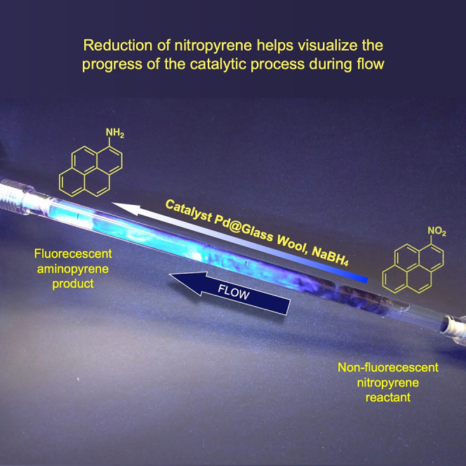
The last entry in Table 2 provides a simple way to visualize the progress of the reaction, as 1-nitropyrene is not fluorescent, whereas 1-aminopyrene is strongly fluorescent. Although the reaction occurs in the dark, weak UVA excitation reveals the progress of the reaction over the 30 cm trajectory of the sample. There is no emission as the sample enters from the right, but emission gradually develops as the reduction progresses and after 20 cm reaches its maximum emission, consistent with the 100% yields observed (Figure 4). Reduction of p-nitrophenol derivatives was also explored (Figure S13). As previously reported (Mitchell et al., 2003), further decomposition of the p-aminophenol product under the reaction conditions played an important role (Figure S13) (Ahmed and Khan, 2000; de Souza et al., 2020).
Figure 4.

Visualized reaction progress
A solution of 0.13 mM 1-nitropyrene and 1.3 mM NaBH4 flows over Pd@GW with a flow rate of 24 mLmin−1 (30 cm tube). Weak UVA light illuminates the tube in order to visualize the reaction progress.
Three reducing agents –sodium borohydride, hydrazine, and hydrogen– were compared in continuous flow System 1 with NB (1mM) and flow rates ca. 4 mLmin−1. Sodium borohydride showed better results than hydrazine in the long-term because of its role in maintaining the catalyst performance. The conversion of NB with hydrazine started to decrease after 10 min (Figure S7). Either hydrogen or NaBH4 acted well as a reducing agent in water and room temperature, then NaBH4 is selected as a safe and clean source of hydrogen generated in situ during the reaction (Kadam and Tilve, 2015). Although in academic labs sodium borohydride is convenient, given the comparable performance, hydrogen gas may be preferred in an industrial setting, as this would reduce the amount of waste generated and the reaction requires neither high pressure nor high temperature.
For higher concentrations of NB, over 12 mM, it is necessary to add a cosolvent to dissolve NB in water; therefore, NaBH4 could not act as effficiently as in pure water and affect the reduction process. Table 2, entry 4 is for 3 mM NB with STY 27.9 gL−1h−1, by increasing concentration of NB to 15 mM (Table 2, entry 5) STY dramatically decreased to 2.7 gL−1h−1 because NaBH4 is not soluble in cosolvent, acetonitrile. In this situation, changing the reducing reagent to H2 gas was helpful as the reaction with 15 mM NB was repeated and STY of 26.5 was obtained (Table 2, entry 6). In another attempt for using higher concentration of reagent, ethanol was used as a cosolvent and H2 gas as a reducing agent; 100 mM of NB was converted with fresh catalyst and STY of 27.1 gL−1h−1 for 3h (Table 2, entry 7 and Figure 5).
Figure 5.

Stability in long-term reaction
Ethanol (50%) was used as a cosolvent and H2 gas as a reducing agent; 100 mM of NB was converted with fresh catalyst and STY of 27.1 gL−1h−1. The graph (red, left axis) shows the stability of samples collected at different times, where most of the absorbance fluctuations (0.34 ± 0.04) are because of sampling, dilution, and measurement factors. The right axis refers to yield as determined by GC. For fresh catalyst, the yield was 100% (dark blue squares) throughout the reaction. Note that it takes about 30 min for the first drops of reaction to exit the tube while starting with a tube containing no liquid. For an old (>11 months) used catalyst, the light blue bars show the yields obtained, fluctuating between 64 and 88% while sampling at different times.
Catalyst stability during use and shelf life
In work of this type, typical shelf-life studies tend to be very limited. In this case, the 2020 COVID-19 pandemic forced lab closures and very limited access upon reopening. As a result, one 30 cm column was stored for about 6-8 months with no special precautions, as such storage was forced rather than planned. Solutions of 0.3–2 mM nitrobenzene tested after storage showed >99% conversion to aniline, just as they had before storage.
For better comparison, we used 10 g Pd@GW that had been used to convert 130 mmol of NB into aniline during a year and compared it with fresh Pd@GW 0.32 wt%. In this trial, NB 100 mM dissolved in 50 v% aqueous ethanol and was pumped with the average flow rate of 3 mLmin−1 in System 2 and H2 gas as a reducing agent. The yield of aniline according to the GC-MS analysis was ∼100% for fresh catalyst and 86% for used one, STY 27.1 and 25.6 gL−1h−1, respectively, see Figure 5. The apparent stability of the catalyst, its longevity, and performance may hide some migration of Pd atoms or clusters, as recently observed for Pd@TiO2 (Costa et al., 2020). However, the sustained performance and minimal leaching suggest that fast Pd redeposition of glass wool minimizes catalyst losses. The GC-MS analysis for the sample of old catalyst in 140 min showed 88.2% aniline, 11.4% nitrobenzene, and 0.4% Azoxybenzene. These results mean that the decrease of aniline yield is caused by decrease of nitrobenzene conversion and by formation of a side product.
Conclusion
The NB to aniline reduction is a major industrial process and the main use of NB worldwide, and a key step in the production of polyurethanes. The catalytic process reported here is easily scalable and operates under exceptionally mild conditions, such as atmospheric pressure, room temperature, and aqueous solution. The process started in batch with STY 0.08 gL−1h−1 and scaled up to ∼28 gL−1h−1 in a continuous flow system. Although the catalyst uses Pd, its loading (0.32 wt%) is lower than usually required (as much as 7 wt%) (Cossaboon, 1980; Ichitsuka et al., 2019; Yamada et al., 2020) and it is reusable many times. Further, in our synthesis, ∼92% of the Pd used is retained in the catalyst. The catalyst is also very robust, through numerous experiments; we never got to deactivate the catalyst, beyond requiring a brief recovery by flowing a NaBH4 solution. Although NaBH4 provides a good reductant for laboratory screening, hydrogen works extremely well under the same mild conditions and should be the preferred reductant in an industrial setting. Glass wool provides a readily available and inexpensive material that can be used as a support, leading to a catalyst that permits easy flow around it, without being lost by the active flow. Further, the Pd@GW catalyst can be readily synthesized in-situ under UVA exposure, thus adding convenience to the overall process. Although this contribution centers on the commercially important nitrobenzene to aniline reduction, a modest exploration of the scope (Table 2) shows that the reaction is quite general.
Limitation of the study
This system is designed for nitro reduction reactions in mild conditions of atmospheric temperature and pressure that works very well for aromatic nitro compounds, but this condition is limiting our system for working with aliphatic nitro compounds that need further developments.
STAR★Methods
Key resources table
| REAGENT or RESOURCE | SOURCE | IDENTIFIER |
|---|---|---|
| Chemicals | ||
| 3-Aminopropyl)triethoxysilane | Sigma Aldrich | Cas# 919-30-2 |
| Palladium(II) acetylacetonate | Sigma Aldrich | CAS# 14024-61-4 |
| Sodium borohydride | Sigma Aldrich | CAS# 16940-66-2 |
| Nitrobenzene | Sigma Aldrich | CAS# 98-95-3 |
| Aniline | Sigma Aldrich | CAS# 62-53-3 |
| 4-Nitrobenzoic acid | Sigma Aldrich | CAS# 62-23-7 |
| 4-Nitroanisole | Sigma Aldrich | CAS# 100-17-4 |
| 1-Nitronaphthalene | Sigma Aldrich | CAS# 86-57-7 |
| 1-Nitropyrene | Sigma Aldrich | CAS# 5522-43-0 |
| Nitrophenol | Sigma Aldrich | CAS# 554-84-7 |
| Irgacure 2959 | BSAF | Cat# 55047962 |
| Ethanol | Fisher chemical | CAS# 64-17-5 |
| Acetonitrile | Fisher chemical | CAS# 75-05-8 |
| Hydrogen | Messer | CAS# 1333-74-0 |
| Other | ||
| Non-treated glass wool | Sigma Aldrich | SKU-Pack Size: 20384 |
| Glass tube 30 cm | Ace glass | 5815-03 |
| Glass tube 150 cm | Macalaster Bicknell | 244140 |
| UVA lamp 8W | Luzchem | LZC-UVA |
| UVA lamp 40W | General Electric | F40BLB-6PK |
| Pump | Masterflex | 7525-34 |
| Expo panel | Luzchem | EXPO-01 |
Resource availability
Lead contact
Further information and requests for resources and reagents should be directed to and will be fulfilled by the lead contact, Juan C. Scaiano (jscaiano@uottawa.ca).
Materials availability
This study did not generate new unique reagents.
Method details
Glass wool pre-treatment
Non-treated glass wool from Sigma Aldrich was immersed in 1% (3-Aminopropyl)triethoxysilane (APTES) solution in toluene and refluxed overnight. After cooling down to room temperature, the glass wool was removed from the flask and rinsed with toluene (3x) and acetone (3x). The APTES treated glass wool was dried in an oven at 100°C overnight (Elhage et al., 2018).
Synthesis of Pd@GW
APTES treated GW (1g) was placed inside a 30 cm tube (ID = 10 mm), ensuring homogeneous distribution of the GW to provide good light penetration inside the tube. A solution with 15 mg of palladium (II) acetylacetonate (Pd(acac)2) – accounting for 0.5 wt% Pd@GW) and 60 mg of Irgacure 2959 (I-2959) – photoinitiator is shown in Scheme S1 – in 26 mL of ethanol was prepared and injected inside the tube. Two sides of the tube were sealed and irradiated with a Luzchem Expo panel fitted with 5 T5 UVA bulbs (8W each) for 210 min and rotated on a hot-dog cooker for homogeneous mixing. The obtained gray glass wool was washed with ethanol inside the tube to remove the unreacted Pd(acac)2 and photoinitiator debris and dried at room temperature. The Pd@GW catalyst was characterized by SEM, XPS and ICP-OES (See Scheme S1, Figures 1, 2, S1, S2, and S4).
Large scale synthesis of Pd@GW
Using the method described above, 10 g of APTES@GW were placed inside a 150 cm tube (ID = 13 mm) and a solution with 100 mg palladium (II) acetylacetonate (Pd(acac)2) – for a nominal 0.35 wt% Pd@GW, and 400 mg of I-2959 in 165 ml ethanol was prepared and injected inside the tube. Two sides of the tube were sealed and irradiated with 4 UV-A bulbs (40 W) for 270 min. The tube was manually rotated every 15 min to ensure a homogeneous mix. The obtained Pd@GW was washed with ethanol and dried at room temperature (See Figure S5).
Calculation of space time yield
Q = Volumetric flow rate (L.h-1)
CNB = Concentration of nitrobenzene (M)
XNB = Conversion of NB
SA = selectivity to aniline
MAn = molar mass of aniline (g.mol-1)
Vreac = reaction volume (L)
τ = residence time (h)
For example, the residence time of the solution of nitrobenzene 3 mM on the surface of 10 g catalyst with flow rate of 100 mLmin–1 is roughly 0.01 h. By considering full conversion of NB to aniline, the values of XNB and SA are 1.
Scope reaction
Reduction of nitro compounds with Pd@GW was done successfully for nitrobenzene, 4-nitrobenzoic acid, 4-nitroanisole, 1-nitronaphthalene, and 1-nitropyrene; however, nitrophenol reduction showed different results. Reduction of nitrophenol (0.45 mM) with 40 mg of Pd@GW in batch yielded 100% conversion to aminophenol, but under flow conditions (500 mg of catalyst, flow rate 2.1 mL/min), another peak appeared, thus suggesting that under prolonged catalyst exposure phenols may undergo other changes. The matter was not pursued any further (see Figures S13 and S14) (Ahmed and Khan, 2000; de Souza et al., 2020).
Acknowledgments
This work was supported by the Natural Sciences and Engineering Research Council of Canada, the Canada Foundation for Innovation, and the Canada Research Chairs Program. We thank Professor Theodore J. Burkey and Dr. Ayda Elhage, whose early experiments stimulated our interest in the scale-up of photochemical synthesis.
Author contributions
Conceptualization, J.C.S. and A.E.L.; Methodology, A.E.L and M.Y.; Investigation, M.Y; Writing – Original Draft, J.C.S. and M.Y.; Writing – Review & Editing, J.C.S., M.Y and A.E.L.; Funding Acquisition, J.C.S.; Resources, J.C.S.; Supervision, J.C.S, and A.E.L.
Declaration of interests
The authors declare no competing interests.
Published: December 17, 2021
Footnotes
Supplemental information can be found online at https://doi.org/10.1016/j.isci.2021.103472.
Supplemental information
Data and code availability
-
•
Microscopy data reported in this paper will be shared by the lead contact upon request.
-
•
No original code was generated in this contribution
-
•
Any additional information required to reanalyze the data reported in this paper is available from the lead contact upon request
References
- Ahmed M., Khan Z.H. Electronic absorption spectra of benzoquinone and its hydroxy substituents and effect of solvents on their spectra. Spectrochim. Acta A Mol. Biomol. Spectrosc. 2000;56:965–981. doi: 10.1016/s1386-1425(99)00190-0. [DOI] [PubMed] [Google Scholar]
- Amini B., Lowenkron S. https://doi-org.nottingham.idm.oclc.org/10.1002/0471238961.0114091201130914.a01.pub2
- Bayer P., Jacobi von Wangelin A. An entirely solvent-free photooxygenation of olefins under continuous flow conditions. Green. Chem. 2020;22:2359–2364. [Google Scholar]
- Colom J., Llobet A., Pla-Quintana A., Roglans A. Preparation of aniline derivatives: an advanced undergraduate laboratory experiment exploring catalytic and stoichiometric reaction methodologies. J. Chem. Educ. 2002;79:731. [Google Scholar]
- Cossaboon, K.F. 1980. Patent: hydrogenation of mixed aromatic nitrobodies. USA patent application US4185036A. Jan 22, 1980.
- Costa P., Sandrin D., Scaiano J.C. Real-time fluorescence imaging of a heterogeneously catalysed Suzuki–Miyaura reaction. Nat. Catal. 2020;3:427–437. [Google Scholar]
- de Souza J.C., Zanoni M.V.B., Oliveira-Brett A.M. Genotoxic permanent hair dye precursors p-aminophenol and p-toluenediamine electrochemical oxidation mechanisms and evaluation in biological fluids. J. Electroanal. Chem. 2020;857:113509. [Google Scholar]
- Elhage A., Wang B., Marina N., Marin M.L., Cruz M., Lanterna A.E., Scaiano J.C. Glass wool: a novel support for heterogeneous catalysis. Chem. Sci. 2018;9:6844–6852. doi: 10.1039/c8sc02115e. [DOI] [PMC free article] [PubMed] [Google Scholar]
- Feng J., Handa S., Gallou F., Lipshutz B.H. Safe and selective nitro group reductions catalyzed by sustainable and recyclable Fe/ppm Pd nanoparticles in water at room temperature. Angew. Chem. Int. Ed. 2016;128:9125–9129. doi: 10.1002/anie.201604026. [DOI] [PubMed] [Google Scholar]
- Fieser L.F. Heath and Co; 1941. Experiments in Organic Chemistry. [Google Scholar]
- Formenti D., Ferretti F., Scharnagl F.K., Beller M. Reduction of nitro compounds using 3d-non-noble metal catalysts. Chem. Rev. 2019;119:2611–2680. doi: 10.1021/acs.chemrev.8b00547. [DOI] [PubMed] [Google Scholar]
- Gholinejad M., Oftadeh E., Shojafar M., Sansano J.M., Lipshutz B.H. Synergistic effects of ppm levels of palladium on natural clinochlore for reduction of nitroarenes. ChemSusChem. 2019;12:4240–4248. doi: 10.1002/cssc.201901535. [DOI] [PubMed] [Google Scholar]
- Global Industry Analysts Global Nitrobenzene Industry. 2021 https://www.reportlinker.com/p06032340/Global-Nitrobenzene-Industry.html?utm_source=GNW [Google Scholar]
- Goszewska I., Giziński D., Zienkiewicz-Machnik M., Lisovytskiy D., Nikiforov K., Masternak J., Śrębowata A., Sá J. A novel nano-palladium catalyst for continuous-flow chemoselective hydrogenation reactions. Catal. Commun. 2017;94:65–68. [Google Scholar]
- Greco R., Goessler W., Cantillo D., Kappe C.O. Benchmarking immobilized Di- and triarylphosphine palladium catalysts for continuous-flow cross-coupling reactions: efficiency, durability, and metal leaching studies. ACS Catal. 2015;5:1303–1312. [Google Scholar]
- Hassan, A., Bagherzadeh, E., Anthony, R.G., Borsinger, G.G. & Hassan, A. 2012. Patent: system and process for production of aniline and toluenediamine. USA patent application 12/568,155. April 10, 2012.
- Hessel V., Löwe H., Hardt S. John Wiley & Sons; 2004. Chemical Micro Process Engineering: Fundamentals, Modelling and Reactions. [Google Scholar]
- Ichitsuka T., Suzuki N., Sairenji M., Koumura N., Onozawa S.-Y., Sato K., Kobayashi S. Readily available immobilized Pd catalysts for Suzuki-Miyaura coupling under continuous-flow conditions. ChemCatChem. 2019;11:2427–2431. [Google Scholar]
- Kadam H.K., Tilve S.G. Advancement in methodologies for reduction of nitroarenes. RSC Adv. 2015;5:83391–83407. [Google Scholar]
- Lippincott D.J., Landstrom E., Cortes-Clerget M., Lipshutz B.H., Buescher K., Schreiber R., Durano C., Parmentier M., Ye N., Wu B., et al. Surfactant technology: with new rules, designing new sequences is required! Org. Process. Res. Dev. 2020;24:841–849. [Google Scholar]
- Lipshutz B.H., Ghorai S., Cortes-Clerget M. The hydrophobic effect applied to organic synthesis: recent synthetic chemistry “in water”. Chem. Eur. J. 2018;24:6672–6695. doi: 10.1002/chem.201705499. [DOI] [PubMed] [Google Scholar]
- Mitchell S.C., Carmichael P., Waring R. Aminophenols. Kirk-Othmer encyclopedia of chemical technology. 2003 doi: 10.1002/0471238961.0113091413092003.a01.pub2. [DOI] [Google Scholar]
- Moghaddam M.M., Pieber B., Glasnov T., Kappe C.O. Immobilized iron oxide nanoparticles as stable and reusable catalysts for hydrazine-mediated nitro reductions in continuous flow. ChemSusChem. 2014;7:3122–3131. doi: 10.1002/cssc.201402455. [DOI] [PubMed] [Google Scholar]
- Orlandi M., Brenna D., Harms R., Jost S., Benaglia M. Recent developments in the reduction of aromatic and aliphatic nitro compounds to amines. Org. Proc. Res. Dev. 2018;22:430–445. [Google Scholar]
- Plutschack M.B., Pieber B., Gilmore K., Seeberger P.H. The Hitchhiker’s guide to flow chemistry. Chem. Rev. 2017;117:11796–11893. doi: 10.1021/acs.chemrev.7b00183. [DOI] [PubMed] [Google Scholar]
- Teixeira R.I., de Lucas N.C., Garden S.J., Lanterna A.E., Scaiano J.C. Glass wool supported ruthenium complexes: versatile, recyclable heterogeneous photoredox catalysts. Catal. Sci. Technol. 2020;10:1273–1280. [Google Scholar]
- Ullmann F., Bohnet M. Wiley; 2009. Ullmann's Encyclopedia of Industrial Chemistry. [Google Scholar]
- Yamada T., Jiang J., Ito N., Park K., Masuda H., Furugen C., Ishida M., Ōtori S., Sajiki H. Development of facile and simple processes for the heterogeneous Pd-catalyzed ligand-free continuous-flow Suzuki–Miyaura coupling. Catalysts. 2020;10:1209. [Google Scholar]
Associated Data
This section collects any data citations, data availability statements, or supplementary materials included in this article.
Supplementary Materials
Data Availability Statement
-
•
Microscopy data reported in this paper will be shared by the lead contact upon request.
-
•
No original code was generated in this contribution
-
•
Any additional information required to reanalyze the data reported in this paper is available from the lead contact upon request