

Abstract

Oil spill accidents contaminate the oceanic environment and cause economic distress, and they continue to occur. Many methods have been developed to restore waters contaminated with spilled oil. However, still most commercially available methods are not environmentally or economically sustainable solutions. Therefore, there is a need for the development of sustainable materials with running water treatment capabilities. In recent years, a polyurethane (PU) sponge-based adsorbent has been reported as an oil–water separation and reusable adsorbent. This is because the porous 3D structure of the PU sponge provides a large surface area. However, as the PU sponge has a carboxyl group and an amino group, it exhibits hydrophilicity, so surface modification is essential for oil–water separation. Therefore, to modify the surface of PU to have hydrophobic/oleophilic properties, a hydrophobic/oleophilic adsorbent (HOA) was prepared using graphite and polydimethylsiloxane. On the basis of this, a PU sponge, a porous material, was used to manufacture an adsorbent that can be used in a sustainable and environmentally friendly way. The prepared HOA can selectively adsorb water or oil and can be reused. Furthermore, continuous oil–water separation is possible through a simple flow of fluid. Therefore, it is confirmed that the studied HOA can have great potential for ocean restoration in the future as an adsorbent that mitigates the disadvantages of the currently commercialized method.
1. Introduction
In the past, the ocean was like a wall that could no longer be crossed, but in the present, it has turned into a stage for transportation and trade and has become a platform for the further development of mankind. However, due to these advances, the sea is polluted by a variety of factors. Among them, oil spill accidents are of great concern to humans, along with increasing environmental problems in recent years.1 Spilled oil forms an oil film on the ocean that causes toxicity and suffocation, resulting in damage to the cellular functions and physical damage, to marine organisms.2 In addition, after a spill, light oil and heavy oil affect the coastal or intertidal zone in different ways over time.2 Accordingly, the importance of rapid recovery in the case of oil accidents is emerging, and adsorbents, dispersants, skimmers, and on-site combustion methods are widely used. While these oil treatment methods are useful in some situations, they have fatal drawbacks in terms of environmental impact. Although an adsorbent has a high adsorption capacity, it generates a lot of waste after use,3 while a dispersant prevents the formation of an oil film but produces fine oil droplets.4 In the case of skimming, oil–water separation is possible, but the adsorption rate is low and the efficiency may not be constant, depending on natural phenomena, such as waves.5 Lastly, the in situ combustion method can be processed quickly but has the disadvantage of generating oxides.6 To solve this problem, a reusable polyurethane (PU) sponge-based adsorbent with hydrophobic/oleophilic properties has been reported for oil–water separation.7−20 This is because the PU sponge has the advantages of high elasticity, elastic recovery, and relatively light weight as an adsorbent and ultimately provides a large surface area due to its porous 3D structure. However, the surface of PU is composed of carboxyl and amino groups and is generally hydrophilic, so a modified form of the surface of the PU sponge is required. For example, by using the sequential infiltration synthesis technique, the deposition parameters are adjusted, and the coating is made as a thin film,7,8 or hydrophobic and magnetic materials are introduced on the base,9−13 or high-density polyethylene is dissolved in an organic solvent to coat PU.10,14 We have paid attention to adsorbents coated with carbon-based materials such as carbon nanotubes (CNTs), nanodiamonds, reduced graphene oxide (RGO), and graphite among various hydrophobic materials.11−13,15−20 This is because carbon-based materials have unique properties of being hydrophobic in air through chemical stability and hydrophobic interactions.21−23 Depending on their shape, these carbon-based materials may provide a large specific surface area. For example, RGO, which increases the specific surface area by generating and reducing graphene oxide through oxidation of graphite,11,15,18,20 and CNTs, which has a large specific surface area with a unique porous structure,13,16,19 are sometimes used. However, these require additional manufacturing processes and costs because of the different forms or structural differences of graphite. Most importantly, when evaluating cytotoxicity using graphite, long multiwalled CNTs, and short multiwalled CNTs, a noticeable increase in reactive oxygen species and a decrease in cell viability were reported in short multiwalled CNTs.24 This is because the large specific surface area of the particles acts as a factor influencing toxicity.25,26 This can cause major problems if leaked during actual use. In contrast, graphite has a relatively low specific surface area.27 Therefore, graphite induces cytotoxicity only at high concentrations, which has been reported as a possible mechanism for oxidative stress.28 In addition, even if graphite loses its hydrophobic properties due to surface modification by ultraviolet rays or ozone, its hydrophobic properties are quickly restored by the adsorption of hydrocarbons in air.21,22 This has important implications for marine environments that are always exposed to ultraviolet rays or ozone. That is why we believe that graphite should be used because it takes advantage of the inherent advantages of carbon-based materials and at the same time has a relatively less environmental impact than other extended carbon-based materials. We used ethanol to effectively disperse graphite and effectively incorporate graphite into the PU sponge base29 and used PDMS for binding the PU sponge surface and graphite.30 In addition, in order to take advantage of the 3D porous structure of the PU sponge, we diluted PDMS to thinly coat it, then subjecting it to a dip-coating process, and cured.30,31 PDMS is a polymer made of silicone that exhibits liquid-like properties. When cross-linked using a curing agent, the properties change to those of a solid.32 Cured PDMS is an inert, chemically stable, hydrophobic polymer with a low surface energy. It can make the surface of PU more hydrophobic.33 That is, as shown in Scheme 1, HOA is first coated with graphite on the surface of PU. It is then prepared by coating PDMS, which acts as a binder between the coated graphite and PU.
Scheme 1. HOA is First Coated with Graphite on the PU Surface.

It is then prepared by coating PDMS, which acts as a binder between the coated graphite and PU.
Furthermore, differences in solubility according to the diluting organic solvent of PDMS have been reported.34 This suggests that the coating may be affected depending on the solvent and the dilution ratio. In summary, our study aims to introduce the chemical stability and hydrophobic properties of carbon-based materials, which are the advantages of carbon-based materials, by coating carbon-based materials on PU sponge bases for oil/water separation. In this case, graphite, which is judged to have little impact on the environment among carbon-based materials, was used. In addition, PDMS was used to introduce graphite on the surface of the PU sponge relatively simply. Additionally, repeated adsorption/desorption processes for oil–water separation may be inefficient. Therefore, the efficiency of the method using the pressure difference caused by the airflow, as in Scheme 2 for continuous oil–water separation with the prepared HOA was tested.
Scheme 2. Continuous Oil–Water Separation Device Using the Pressure Difference.
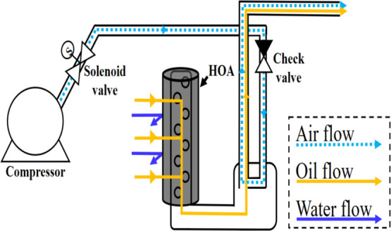
The features are that the air inlet and the oil outlet are separated, and only the adsorbent is replaced at the same time as oil/water separation, so that the performance of the device is maintained.
2. Results and Discussion
2.1. Preparation and Characterization of HOA
Graphite and PDMS were sequentially dip-coated onto the PU base. At this time, to completely wet the solid with the solution, the surface energy of the solution must be lower than the surface energy of the solid.35,36 Therefore, using ethanol, which has a lower surface energy than PU and can disperse graphite well, a dip coating of graphite on PU can be smoothly performed.35,37 The surface of graphite-coated PU was studied from Figure 1a, which was obtained using a scanning electron microscope. In addition, it can be seen from Figure 1b–d that when the above process is repeated, the roughness of the surface increases as the content of graphite to be coated increases. However, if the number of repetitions is further increased, graphite is coated in a multilayer, which can be easily removed or detached because the secondary junction of additional graphite is coated on graphite in a multilayer form in the primary junction. This is due to the π interaction, which is an electrostatic force due to the π structure of graphite.38,39 This is a state in which graphite is weakly bonded to the PU base or bonded to graphite. This is the reason why we used PDMS for binding. Furthermore, to use the 3D porous structure of the PU sponge during the secondary coating process, PDMS must be thinly coated as a secondary coating material. Therefore, even if the number of coatings is increased, the loss of graphite not bound to PDMS occurs. On the one hand, Figure S1 of the Supporting Information shows the mass and contact angle for different graphite coating methods. At this time, the increase in the coating content of graphite was confirmed in samples that were dip-coated several times. However, there is no increase in the content in the dip coating process according to the excess content of graphite. It is believed that excess graphite was easily desorbed during the coating process, and no increase in weight was observed. In other words, if graphite is dip-coated several times, it means that the already coated graphite is not easily desorbed and is coated effectively. These results suggest that the graphite and PDMS diluent can be easily desorbed when one-pot dip coating is performed. Therefore, we coated PDMS after coating graphite on the surface of the PU sponge.
Figure 1.

SEM measurement by repeating the number of graphite coatings; (a) pristine sponge, (b) 1× coating, (c) 2× coating, and (d) 3× coating.
Then, with graphite coated on PU in a monolayer, PDMS was dip-coated in a solution diluted with toluene to bind the empty space between PU and graphite. After that, it was cured in an oven and thinly coated. The cured PDMS is a hydrophobic polymer that is an inert substance, chemically stable, and has low surface energy, and can make the surface of PU more hydrophobic.33 As a result (Figure S2 of the Supporting Information), when PDMS is coated, the water contact angle (WCA) increases, as compared with that when only graphite is coated. However, the contact angle, according to the PDMS content, does not show a significant change. Also, Figure 2 shows that the lower the dilution ratio, the more is the surface of the primary bonded graphite that is covered. Figure 2a shows that the higher the dilution rate, the higher is the degree of exposure of the graphite surface. Also, if the dilution rate is too high, it can play a weak binding role.
Figure 2.

SEM measurement according to the PDMS content: (a) PDMS, 0.25 g; (b) PDMS, 0.5 g; (c) PDMS, 1 g; and (d) PDMS, 2 g.
Moreover, Figure S3 of the Supporting Information shows that as the content of PDMS increases, the space inside the sponge becomes smaller, and the adsorption rate decreases. Therefore, the content of PDMS was determined to be 0.25 g, and the curing agent was prepared in a ratio of 10:1. As a result of the inductively coupled plasma-optical emission spectroscopy (ICP-OES) measurement of the final HOA prepared in this way, it was confirmed that the Si element was (3.12 ± 0.24) wt % of the total weight. The cause of the error appears to be due to the irregular porous structure of the sponge. Figure 3a shows that for the HOA fabricated through the above process, WCA increased from 85.5° ± 3° to 145° ± 5.5°. It sometimes exhibits more than 150°, indicating superhydrophobicity.
Figure 3.

(a) WCA measurement before and after coating: PU based on coating has an initial WCA of 85.5° ± 3°, but after surface coating, it increased to 145° ± 5.5°. (b) Oil red O chloroform/DW separation: it was confirmed that only chloroform could be selectively adsorbed. (c) Drop scene by solvent type: when DW, xylene, and gasoline are dropped with a micropipette, and only DW creates water droplets.
2.2. Oil/Water Separation Test
HOA with hydrophobic properties did not adsorb distilled water (DW) but only adsorbed xylene and gasoline (see Figure 3c and Movie S1 of the Supporting Information). The oil–water separation test shows hydrophobicity/oleophilicity that can selectively adsorb only chloroform between chloroform and DW as an alternative oil dyed with oil red O (see Figure 3b and Movie S2 of the Supporting Information). These results suggest that the prepared HOA may be capable of oil–water separation in water containing sinking oil, such as a water column.
2.3. Mass Adsorption Capacity and Reusability
The adsorption capacity of HOA prepared using toluene, xylene, hexane, gasoline, chloroform, silicone oil, and soybean oil, among various organic solvents and oils widely used in industry and daily life, was evaluated. HOA shows high adsorption of these substances (Figure 4).
Figure 4.

Mass adsorption capacity by organic solvent type. The prepared HOA has various adsorption rates, depending on the type of organic solvent.
The adsorption capacity of the prepared HOA is different for each organic solvent because the adsorption rate depends mainly on the density of the organic solvent. For example, the adsorption capacity of HOA for chloroform (1.49 g/cm3) was about 48 g/g, and for hexane (0.65 g/cm3), the adsorption capacity was about 21 g/g. Additionally, the kinematic viscosity and surface tension of the organic solvent may affect the adsorption capacity. Table S1 of the Supporting Information lists the density, kinematic viscosity, and surface tension of the organic solvents used. In contrast, Table S2 of the Supporting Information compares the adsorption capacity of adsorbents coated with carbon-based materials based on PU sponges previously studied based on the adsorption capacity of hexane and gasoline in HOA.11,15−20 Although the adsorption capacity is different, the prepared adsorbent is more efficient in terms of cost and time when considering the time and cost required for the manufacturing process of carbon-based materials such as reduced graphene oxide. Also, in the case of the reusability test, Figure 5 shows that the adsorption amount during 10 cycles did not change significantly. In addition, the WCA measurements shows that it can be regarded as being reusable because the WCA is 90° or more and is therefore hydrophobic. Movie S3 of the Supporting Information shows that the reusability can also be confirmed when used between DW and gasoline.
Figure 5.

Mass adsorption capacity and WCA by cycle. The adsorption rate was measured using the fabricated HOA and gasoline, and the WCA was measured using DW. The adsorption rate and WCA were maintained during 10 repetitions.
2.4. Continuous Oil Removal Test of HOA
The HOA is confirmed to be reusable. However, if the adsorption/dehydration cycle should be repeated, such as squeezing the sponge, it would be difficult to apply to a real separation system. Therefore, organic contaminants must be able to be continuously adsorbed and removed. Accordingly, a continuous process is proposed using pressure difference (Scheme 2). As the air flows through the pipe, the pressure inside the pipe becomes lower than the external pressure. Due to the pressure difference, the organic pollutants flow into the pipe and go out with the airflow. The emission rate changes depending on the detailed location or length of the device. The test conditions (length, width, organic pollutant volume, etc.) were maintained in the same way as described in Section 4.6. The experimental setup was adjusted to maximize the emission rate. Gasoline was used as an organic pollutant. Figure 6 and Movie S4 of the Supporting Information show that if the air flows weakly, gasoline cannot be drawn in, while if the air flows too fast, the air will be directed to the HOA and causes bubbles. The emission rate showed the highest value when the compressor pressure was 0.05 MPa. As a result, the oil–water separation test was performed at the air pressure of 0.05 MPa. It was confirmed that only gasoline was continuously removed between water and gasoline using a simple principle through the flow of air (Movie S5 of the Supporting Information).
Figure 6.

Emissions from the organic pollutant treatment sustained. If the airflow is weak, gasoline is not raised, and the emission rate is low. When the airflow is strong, air is directed toward the HOA. Therefore, bubbles are generated toward the solution, resulting in low emissions (Movie S4 of the Supporting Information).
3. Conclusions
Depending on the easily available PU, the surface of PU is first coated with graphite, which is known to be hydrophobic in air; then, PDMS with a low surface energy is secondarily coated on the first coating. HOA was fabricated through a binding process in the empty space between PU and graphite in a monolayer coated with graphite on PU. The HOA was inexpensive, easy to make, could be selectively adsorbed between water and oil, and at the same time could be reused. Further, continuous oil–water separation is possible in the process through simple fluid flow, and it is confirmed that there is great potential in the form that complements the shortcomings of the current commercialized methods.
4. Experimental Section
4.1. Materials
The base PU sponge (25 kg/m3) was obtained from Total Sponge Co., Ltd. Graphite powder has a size of 20 μm or less as a coating material, and the products of Sigma-Aldrich Chemistry Co., Ltd. were used. Ethanol (99.0%, C2H5OH) for dispersing graphite was purchased from Samchun Pure Chemical Co., Ltd. Dow Corning Sylgard 184 base and curing agent product was used as the curing agent for curing PDMS and PDMS with another coating material. Toluene (99.9%, C7H8) used for diluting PDMS was a product of SK Chemicals. For performance testing, we used gasoline, a product of SK energy, soybean oil, xylene (99.0%, C8H10), a Sigma-Aldrich Co., Ltd. product, and hexane (99.9%, C6H6) and chloroform (99.5%, CHCl3) from Samchun Pure Chemical Co., Ltd. For silicone oil, KF-96 from Shin-Etsu Chemical Co., Ltd. was used. Lastly, oil red O (dye content ≥ 75%, C26H24N4O) used for dyeing organic solvents was purchased from Sigma-Aldrich. Co., Ltd.
4.2. Sample Preparation
4.2.1. Step 1: Graphite Coating on PU
To coat graphite on PU, graphite powder (0.2 wt %) was added to ethanol and dispersed for 20 min. The prepared base PU sponge (25 kg/m3, 1 cm × 1 cm × 2 cm) was immersed into the dispersed solution and dip-coated for 1 min. After that, it was dried for 3 h at 80 °C through oven-drying. In addition, the above process was repeated several times to allow more graphite to be coated onto the PU sponge surface.
4.2.2. Step 2: Binder Coating between Graphite Coated on PU
In order to thinly coat PDMS, which can serve as a binder between the coated graphite and PU, certain amounts of PDMS and curing agent were added to toluene (100 mL) at a weight ratio of 10:1 and diluted through stirring for 20 min. The adsorbent prepared in the first coating process was then dip-coated in the diluted solution for 1 min. Finally, the HOA was prepared by drying in oven at 60 °C overnight (Scheme 1).
4.3. Characterization
After primary graphite coating, the graphite content was calculated according to eq 1
| 1 |
QW: graphite content ratio to total weight; AC: graphite-coated sponge weight; and AB: base sponge.
To analyze the surface of HOA, it was subjected to Ar sputtering treatment and then SEM (Hitachi, S-3000N, Japan) was carried out at 25 kV. In addition, ICP-OES (PerkinElmer, OPTIMA 5300DV, U.S.) was used to identify the PDMS coatings and Si elements in the final fabricated HOA. A WCA measuring device (Rame-Hart Instrument Co., Goniometer 100-00-115, US) was used to check the wettability of the surface. The tangent method was used to measure the contact angle, considering the nonsmooth surface due to the nature of the sponge. First, an imaginary point is drawn on the surface of the liquid droplet, and an imaginary circle is drawn connecting the points. The tangent of the imaginary circle is drawn to measure the angle between the surface and the tangent. At this time, the left and right contact angles are measured, and the rough surface is corrected by averaging these values.
4.4. Oil/Water Separation Test
To check whether the prepared HOA is capable of oil/water separation in water containing sunken oil, chloroform, an organic solvent, was used as an oil substitute by dyeing with oil red O. Then, the dyed chloroform was added to the prepared DW, and the prepared HOA was added to confirm that only chloroform was selectively adsorbed.
4.5. Mass Adsorption Capacity and Reusability
The oil adsorption of the prepared HOA was calculated according to eq 2. In addition, to check the reusability, the above process was repeated and calculated according to eq 3
| 2 |
| 3 |
QM: adsorption capacity; AW: HOA weight after adsorption; AD: HOA weight in dry condition; QR: adsorption capacity when reused; and AS: HOA weight after squeeze.
4.6. Continuous Oil Removal Test Using HOA
This experiment was conducted to test the continuous oil separation capacity of the fabricated HOA. Scheme 2 shows the schematic of the experimental device. The experiment was performed under the following conditions. The prepared HOA (height 50 mm/thickness 20 mm) was wrapped in the device (diameter 12 mm). Also, the volume of the solvent was filled to 1.8 L. HOA was prepared in a state completely immersed in the solvent. Finally, all tube diameters were different, but the air pressure was kept constant.
Acknowledgments
This research was supported by X-mind Corps program of National Research Foundation of Korea (NRF) funded by the Ministry of Science, ICT (NRF-2019H1D8A1105647). This work was financially supported by a NRF grant funded by the Ministry of Education (NRF-2019R1F1A104530513).
Supporting Information Available
The Supporting Information is available free of charge at https://pubs.acs.org/doi/10.1021/acsomega.1c05301.
First coating process; secondary coating process; weight adsorption rate of gasoline after coating the sponge; physical parameters of organic matter used for the adsorption capacity performance test; and comparison of adsorption power with other PU sponge adsorbents coated with carbon-based materials (PDF)
Each type of solvent dropped into the prepared HOA using a pipette (MP4)
Adsorption of a small amount of chloroform dyed with oil red O (MP4)
Oil–water separation test for multiple cycles (MP4)
Performance test according to the airflow rate (MP4)
Continuous oil–water separation system (MP4)
Author Contributions
S.M.K. and Y.H. equally contributed to the work. Y.H.N. and N.-I.W. perceived the idea and designed the experiments. S.M.K., N.-I.W., and Y.H. developed the materials and performed the characterization. S.M.K., Y.H., and Y.H.N. analyzed the data. S.M.K., Y.H., and Y.H.N. wrote the paper. All authors have reviewed the manuscript and approved the final version of the manuscript.
The authors declare no competing financial interest.
Supplementary Material
References
- Cakir E.; Sevgili C.; Fiskin R. An analysis of severity of oil spill caused by vessel accidents. Transport. Res. Transport Environ. 2021, 90, 102662. 10.1016/j.trd.2020.102662. [DOI] [Google Scholar]
- Technical Information Papers . TIP 13: Effects of Oil Pollution on the Marine Environment; International Tanker Owners Pollution Federation (ITOPF): London, 2014.
- Ge J.; Zhao H. Y.; Zhu H. W.; Huang J.; Shi L. A.; Yu S. H. Advanced sorbents for oil-spill cleanup: recent advances and future perspectives. Adv. Mater. 2016, 28, 10459–10490. 10.1002/adma.201601812. [DOI] [PubMed] [Google Scholar]
- Kujawinski E. B.; Kido Soule M. C.; Valentine D. L.; Boysen A. K.; Longnecker K.; Redmond M. C. Fate of Dispersants Associated with the Deepwater Horizon Oil Spill. Environ. Sci. Technol. 2011, 45, 1298–1306. 10.1021/es103838p. [DOI] [PubMed] [Google Scholar]
- Broje V.; Keller A. A. Improved mechanical oil spill recovery using an optimized geometry for the skimmer surface. Environ. Sci. Technol. 2006, 40, 7914–7918. 10.1021/es061842m. [DOI] [PubMed] [Google Scholar]
- Zengel S. A.; Michel J.; Dahlin J. A. Environmental Effects of In Situ Burning of Oil Spills in Inland and Upland Habitats. Spill Sci. Technol. Bull. 2003, 8, 373–377. 10.1016/s1353-2561(03)00051-3. [DOI] [Google Scholar]
- Barry E.; Mane A. U.; Libera J. A.; Elam J. W.; Darling S. B. Advanced Oil Sorbents Using Sequential Infiltration Synthesis. J. Mater. Chem. A 2017, 5, 2929–2935. 10.1039/c6ta09014a. [DOI] [Google Scholar]
- Barry E.; Libera J. A.; Mane A. U.; Avila J. R.; Devitis D.; van Dyke K.; Elam J. W.; Darling S. B. Mitigating Oil Spills in the Water Column. Environ. Sci.: Water Res. Technol. 2018, 4, 40–47. 10.1039/c7ew00265c. [DOI] [Google Scholar]
- Guselnikova O.; Barras A.; Addad A.; Sviridova E.; Szunerits S.; Postnikov P.; Boukherroub R. Magnetic Polyurethane Sponge for Efficient Oil Adsorption and Separation of Oil from Oil-in-Water Emulsions. Sep. Purif. Technol. 2020, 240, 116627. 10.1016/j.seppur.2020.116627. [DOI] [Google Scholar]
- Yu T.; Halouane F.; Mathias D.; Barras A.; Wang Z.; Lv A.; Lu S.; Xu W.; Meziane D.; Tiercelin N.; Szunerits S.; Boukherroub R. Preparation of Magnetic, Superhydrophobic/Superoleophilic Polyurethane Sponge: Separation of Oil/Water Mixture and Demulsification. Chem. Eng. J. 2020, 384, 123339. 10.1016/j.cej.2019.123339. [DOI] [Google Scholar]
- Jamsaz A.; Goharshadi E. K.; Barras A.; Ifires M.; Szunerits S.; Boukherroub R. Magnetically Driven Superhydrophobic/Superoleophilic Graphene-Based Polyurethane Sponge for Highly Efficient Oil/Water Separation and Demulsification. Sep. Purif. Technol. 2021, 274, 118931. 10.1016/j.seppur.2021.118931. [DOI] [Google Scholar]
- Nandwana V.; Ribet S. M.; Reis R. D.; Kuang Y.; More Y.; Dravid V. P. OHM Sponge: A Versatile, Efficient, and Ecofriendly Environmental Remediation Platform. Ind. Eng. Chem. Res. 2020, 59, 10945–10954. 10.1021/acs.iecr.0c01493. [DOI] [Google Scholar]
- Gui X.; Zeng Z.; Lin Z.; Gan Q.; Xiang R.; Zhu Y.; Cao A.; Tang Z. Magnetic and Highly Recyclable Macroporous Carbon Nanotubes for Spilled Oil Sorption and Separation. ACS Appl. Mater. Interfaces 2013, 5, 5845–5850. 10.1021/am4015007. [DOI] [PubMed] [Google Scholar]
- Cheng Y.; Wu B.; Ma X.; Lu S.; Xu W.; Szunerits S.; Boukherroub R. Facile Preparation of High Density Polyethylene Superhydrophobic/Superoleophilic Coatings on Glass, Copper and Polyurethane Sponge for Self-Cleaning, Corrosion Resistance and Efficient Oil/Water Separation. J. Colloid Interface Sci. 2018, 525, 76–85. 10.1016/j.jcis.2018.04.075. [DOI] [PubMed] [Google Scholar]
- Xia C.; Li Y.; Fei T.; Gong W. Facile One-Pot Synthesis of Superhydrophobic Reduced Graphene Oxide-Coated Polyurethane Sponge at the Presence of Ethanol for Oil-Water Separation. Chem. Eng. J. 2018, 345, 648–658. 10.1016/j.cej.2018.01.079. [DOI] [Google Scholar]
- Wang C.-F.; Lin S.-J. Robust Superhydrophobic/Superoleophilic Sponge for Effective Continuous Absorption and Expulsion of Oil Pollutants from Water. ACS Appl. Mater. Interfaces 2013, 5, 8861–8864. 10.1021/am403266v. [DOI] [PubMed] [Google Scholar]
- Cao N.; Yang B.; Barras A.; Szunerits S.; Boukherroub R. Polyurethane Sponge Functionalized with Superhydrophobic Nanodiamond Particles for Efficient Oil/Water Separation. Chem. Eng. J. 2017, 307, 319–325. 10.1016/j.cej.2016.08.105. [DOI] [Google Scholar]
- Cao N.; Lyu Q.; Li J.; Wang Y.; Yang B.; Szunerits S.; Boukherroub R. Facile Synthesis of Fluorinated Polydopamine/Chitosan/Reduced Graphene Oxide Composite Aerogel for Efficient Oil/Water Separation. Chem. Eng. J. 2017, 326, 17–28. 10.1016/j.cej.2017.05.117. [DOI] [Google Scholar]
- Wang H.; Wang E.; Liu Z.; Gao D.; Yuan R.; Sun L.; Zhu Y. A Novel Carbon Nanotubes Reinforced Superhydrophobic and Superoleophilic Polyurethane Sponge for Selective Oil-Water Separation through a Chemical Fabrication. J. Mater. Chem. A 2015, 3, 266–273. 10.1039/c4ta03945a. [DOI] [Google Scholar]
- Zhou S.; Hao G.; Zhou X.; Jiang W.; Wang T.; Zhang N.; Yu L. One-Pot Synthesis of Robust Superhydrophobic, Functionalized Graphene/Polyurethane Sponge for Effective Continuous Oil-Water Separation. Chem. Eng. J. 2016, 302, 155–162. 10.1016/j.cej.2016.05.051. [DOI] [Google Scholar]
- Kozbial A.; Li Z.; Sun J.; Gong X.; Zhou F.; Wang Y.; Xu H.; Liu H.; Li L. Understanding the intrinsic water wettability of graphite. Carbon 2014, 74, 218–225. 10.1016/j.carbon.2014.03.025. [DOI] [Google Scholar]
- Kozbial A.; Zhou F.; Li Z.; Liu H.; Li L. Are graphitic surfaces hydrophobic?. Acc. Chem. Res. 2016, 49, 2765–2773. 10.1021/acs.accounts.6b00447. [DOI] [PubMed] [Google Scholar]
- Toyoda M.; Inagaki M. Heavy oil sorption using exfoliated graphite: New application of exfoliated graphite to protect heavy oil pollution. Carbon 2000, 38, 199–210. 10.1016/s0008-6223(99)00174-8. [DOI] [Google Scholar]
- Azari M. R.; Mohammadian Y. Comparing in vitro cytotoxicity of graphite, short multi-walled carbon nanotubes, and long multi-walled carbon nanotubes. Environ. Sci. Pollut. Res. Int. 2020, 27, 15401–15406. 10.1007/s11356-020-08036-4. [DOI] [PubMed] [Google Scholar]
- Sukhanova A.; Bozrova S.; Sokolov P.; Berestovoy M.; Karaulov A.; Nabiev I. Dependence of Nanoparticle Toxicity on Their Physical and Chemical Properties. Nanoscale Res. Lett. 2018, 13, 44. 10.1186/s11671-018-2457-x. [DOI] [PMC free article] [PubMed] [Google Scholar]
- Sahu D.; Kannan G. M.; Vijayaraghavan R. Carbon Black Particle Exhibits Size Dependent Toxicity in Human Monocytes. Int. J. Inflamm. 2014, 2014, 827019. 10.1155/2014/827019. [DOI] [PMC free article] [PubMed] [Google Scholar]
- Shornikova O. N.; Kogan E. v.; Sorokina N. E.; Avdeev V. v. The Specific Surface Area and Porous Structure of Graphite Materials. Russ. J. Phys. Chem. A 2009, 83, 1022–1025. 10.1134/s0036024409060260. [DOI] [Google Scholar]
- Anderson R. S.; Thomson S. M.; Gutshall L. L. Comparative Effects of Inhaled Silica or Synthetic Graphite Dusts on Rat Alveolar Cells. Arch. Environ. Contam. Toxicol. 1989, 18, 844–849. 10.1007/bf01160299. [DOI] [PubMed] [Google Scholar]
- Hadi A.; Karimi-Sabet J.; Moosavian S. M. A.; Ghorbanian S. Optimization of graphene production by exfoliation of graphite in supercritical ethanol: A response surface methodology approach. J. Supercrit. Fluids 2016, 107, 92–105. 10.1016/j.supflu.2015.08.022. [DOI] [Google Scholar]
- Con C.; Cui B. Effect of mold treatment by solvent on PDMS molding into nanoholes. Nanoscale Res. Lett. 2013, 8, 394. 10.1186/1556-276X-8-394. [DOI] [PMC free article] [PubMed] [Google Scholar]
- Koo N.; Bender M.; Plachetka U.; Fuchs A.; Wahlbrink T.; Bolten J.; Kurz H. Improved mold fabrication for the definition of high quality nanopatterns by Soft UV-Nanoimprint lithography using diluted PDMS material. Microelectron. Eng. 2007, 84, 904–908. 10.1016/j.mee.2007.01.017. [DOI] [Google Scholar]
- Hopf R.; Bernardi L.; Menze J.; Zündel M.; Mazza E.; Ehret A. E. Experimental and theoretical analyses of the age-dependent large-strain behavior of Sylgard 184 (10:1) silicone elastomer. J. Mech. Behav. Mater. 2016, 60, 425–437. 10.1016/j.jmbbm.2016.02.022. [DOI] [PubMed] [Google Scholar]
- Mata A.; Fleischman A. J.; Roy S. Characterization of polydimethylsiloxane (PDMS) properties for biomedical micro/nanosystems. Biomed. Microdevices 2005, 7, 281–293. 10.1007/s10544-005-6070-2. [DOI] [PubMed] [Google Scholar]
- Lee J. N.; Park C.; Whitesides G. M. Solvent compatibility of poly (dimethylsiloxane)-based microfluidic devices. Anal. Chem. 2003, 75, 6544–6554. 10.1021/ac0346712. [DOI] [PubMed] [Google Scholar]
- Wang Y.; Zhu Y.; Zhang C.; Li J.; Guan Z. Transparent, superhydrophobic surface with varied surface tension responsiveness in wettability based on tunable porous silica structure for gauging liquid surface tension. ACS Appl. Mater. Interfaces 2017, 9, 4142–4150. 10.1021/acsami.6b12779. [DOI] [PubMed] [Google Scholar]
- Szymczyk K.; Zdziennicka A.; Krawczyk J.; Jańczuk B. Wettability, adhesion, adsorption and interface tension in the polymer/surfactant aqueous solution system. I. Critical surface tension of polymer wetting and its surface tension. Colloids Surf., A 2012, 402, 132–138. 10.1016/j.colsurfa.2012.02.054. [DOI] [Google Scholar]
- Zhai M.; Mckenna G. B. Elastic modulus and surface tension of a polyurethane rubber in nanometer thick films. Polymer 2014, 55, 2725–2733. 10.1016/j.polymer.2014.04.010. [DOI] [Google Scholar]
- Kertesz M. Pancake Bonding: An Unusual Pi-Stacking Interaction. Chem.—Eur. J. 2019, 25, 400–416. 10.1002/chem.201802385. [DOI] [PubMed] [Google Scholar]
- Pérez E. M.; Martín N. π-π Interactions in Carbon Nanostructures. Chem. Soc. Rev. 2015, 44, 6425–6433. 10.1039/c5cs00578g. [DOI] [PubMed] [Google Scholar]
Associated Data
This section collects any data citations, data availability statements, or supplementary materials included in this article.