Abstract
The construction of an artificial biological logic circuit using systematic strategy is recognised as one of the most important topics for the development of synthetic biology. In this study, a real‐structured genetic algorithm (RSGA), which combines general advantages of the traditional real genetic algorithm with those of the structured genetic algorithm, is proposed to deal with the biological logic circuit design problem. A general model with the cis ‐regulatory input function and appropriate promoter activity functions is proposed to synthesise a wide variety of fundamental logic gates such as NOT, Buffer, AND, OR, NAND, NOR and XOR. The results obtained can be extended to synthesise advanced combinational and sequential logic circuits by topologically distinct connections. The resulting optimal design of these logic gates and circuits are established via the RSGA. The in silico computer‐based modelling technology has been verified showing its great advantages in the purpose.
Inspec keywords: biocomputing, biological techniques, combinational circuits, genetic algorithms, logic design, logic gates, sequential circuits
Other keywords: in silico computer‐based modelling, RSGA, sequential logic circuits, XOR gates, NOR gates, NAND gates, OR gates, AND gates, Buffer gates, NOT gates, fundamental logic gates, cis‐regulatory input function, real‐structured genetic algorithm, artiflcial biological logic circuit design
1 Introduction
Building biologic circuit by adopting artificial logic components has been regarded as a significant tendency in the research of synthetic biology, which shows an interdisciplinary application in molecular biology and engineering. Information establishment of the bio‐computing process is based on the concentrations of biochemical molecules like voltage signals in electrical circuits. The ultimate goal is to construct the systems integrating very‐large‐scale integration (VLSI) bio‐circuits and bio‐chips, which are similar to those in the field of electrical engineering. Inspired by electronic logic elements, several recent studies have stated the possibility of realising a genetic circuit, which is foreseen to have significant contribution to cancer medicine as well as to a variety of bio‐energy sources [1, 2].
For designing bio‐systems, a variety of optimisation algorithms were taken into consideration in the literature. Among the algorithms, genetic algorithms (GAs) [3] have been well applied in solving engineering optimisation problems introduced into this area. Conventional binary GAs (BGAs) emphasise binary coding in chromosomes, but the kind of evolutionary computational techniques spend excessive computing time when dealing with high‐dimensional problems, and exhibit the problem of premature convergence of solutions. To compensate for the ineffective computational performance of BGAs, the real genetic algorithm (RGA) was developed, which changes in floating point coding of chromosomes and proven to have advantages in computing speed and solution precision [4]. Furthermore, structured genetic algorithm (SGA) and hierarchical genetic algorithm (HGA) have been further proposed to solve the structured optimisation problems [5, 6]. Combining the advantages of RGA and SGA, a novel real‐structured genetic algorithm (RSGA) is proposed to solve the complex multi‐objective optimisation problems, which achieves the compact structure and parameter optimisation simultaneously [7, 8].
Logic computation in living organism is a novel viewpoint that brings the idea in digital logic design into biological systems. Many biological logic behaviours such as NOT, AND, OR, NAND, NOR and XOR have been recently developed in the existing studies [9–19]. In fact, biochemists constructed chemical reactions from the logic phenomenon that responses cellular and environmental molecular signals in vivo, and these chemical reactions can be further described as a set of differential equations. The steady‐state solution of these differential equations can be obtained from the mathematical model that expresses the relation between input and output of the given chemical reaction. However, these models are usually too complicated to be standardised to construct large‐scaled circuits. To obtain a canonical form, cellular transcription process plays an important role in the development of artificial genetic regulatory gates. The transcription factors (TFs) regulate genes by binding particular DNA sites. cis ‐Regulatory input function (CRIF) can describe the combined effect of the promoters and logic phenotype [20–26]. Using this quantitative model, one is able to synthesise different kinds of logic gates by selecting the strengths and related DNA binding sites in the gene's cis ‐regulatory region [21]. To realise different transcription control characteristics in the same cis ‐regulatory construction, adjusting different parameters into general forms have been discussed in [22, 23].
In this paper, we exploited biological logic phenomenon of CRIF and general transcription control characteristics to characterise a novel general mathematical model that can be used to synthesise various genetic logic gates. Here, the problem of biological logic gate design in CRIF is formulated as the problem of optimising the model and its parameters. In [20–23], optimisation algorithms such as neural network and evolution algorithm were proposed for searching the fittest transcription logic phenomenon. However, these approaches generate irregular structure of model and lack the function of model simplification. Therefore they are not suitable for the design of more complex biological logic circuits. To remedy this issue, we propose the RSGA for transcription gate designing. RSGA not only searches optimal parameters including independent binding strengths of RNA polymerase (RNAp) concentration, and cooperativity, but also enables variation and simplification of the CRIF model by introducing extra exponential parameters. The structured genetic mapping in RSGA is utilised to change the optimal model structure so that the CRIF models display the desired functional values of logical expressions on each of their functional arguments. In silico analyses show that the proposed design algorithm outperforms the neural network and the conventional evolution algorithm.
Through synchronised cascades of designed transcription gates, moreover, biological Boolean circuits can be realised. In particular, one can realise more complicated systems, such as bio‐combinational logic circuits, sequential logic circuits and biological logic devices and circuits that spring from some specific electric logic circuits. On the bases of these designs, it is expected that a biological computer might be implementable in the future.
From the above arguments, this study attempts to develop a more efficient method for solving the structure and parameter optimisation problems in design of biological logic gates. Numerical experiments show that RSGA approach is effective in obtaining bio‐logic gates with the cheapest structures. Moreover, we have extended our approach to bio‐circuits, which has become a significant foundation for bio‐computer design. The results presented in this paper show the promising possibility for future development in biological engineering.
2 Real‐structured genetic algorithm (RSGA)
The RSGA, which is a method for searching both the optimal parameters and the optimal structure, is developed by combining the RGA with the advantages of SGA. The genetic operations of RSGA include reproduction, crossover and mutation, which were pioneered by Tsai et al. [7, 8]. The major difference between RSGA and SGA is that, for the RSGA, both of the control and parameter genes are in real numbers, which involves more sophisticated parameter mapping and improves efficiency in its computational mechanism due to the consistency of the crossover and the mutation operators. Moreover, the dynamic probability regulation, based on the idea of Butterworth filter, is used to control the crossover/mutation probability, it optimises the bio‐CRIF modelling structure in the earlier phase and automatically switches its emphasis to the model's parameters in the latter phase. Besides, the structured regulation of the RSGA makes that the genes on the higher levels determine whether the genes on the lower levels should become activated, deactivated or linear ratio variation rather than just turn genes on or off. That brings more variability during the gene evolution than the traditional SGA.
The structured mapping generates different structures corresponding to different biological network and exhibits the possibility of searching out the optimal one in the sense of the optimal structure and optimal parameters. The feature depicted shows RSGA's advantages in achieving the optimal structure and optimal parameters for broaden applications in the design of synthetic biological devices.
2.1 Structured genetic mapping
Fundamental operation of RSGA [7, 8] is introduced first. The chromosomes consist of the control gene strings c = [ci ] and the parameter gene strings p = [pi ] which are both real numbers within the interval (R min, R max). The parameter genes are regulated by the control genes to change the structure of bio‐CRIF model as described later. RSGA structured mapping possesses three operations, namely, activate, inhibit and linear ratio scaling. The operating function of control genes is determined by the correlation between the control genes, B max and B min. When the value of control gene is greater than B max, the corresponding parameter gene is activated (ON). On the other hand, if its value is less than B min, the corresponding parameter gene is inhibited (OFF). When its value lies within (B min, B max), the corresponding parameter gene is regulated by a linear scaling factor. The idea behind the structural mapping can be illustrated in Fig. 1.
Fig. 1.
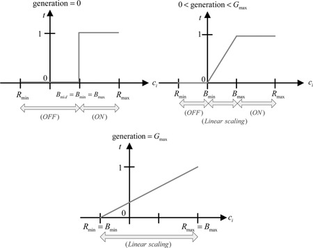
Activation function for structural genetic mapping
The mathematical model of structured genetic mapping from c to p is defined as
| (1) |
where
| (2) |
with
where represents an ordered set consisting of c and new parameter strings , the operator ⊗ is called as the genetic switch, which represents the operation of structured genetic mapping, and ϕ denotes an empty that corresponds to the term to be ignored. Variations in B max and B min are defined by the following boundary sizing rules
| (3) |
where R mid = (1/2)(R max + R min) and R max and R min are, respectively, the maximum and minimum boundaries, gi denotes the current generation, g init and g fin are the initial and final generations, and ΔB = kgi , with k being a positive constant. This mechanism allows vibrant alternation of parameter genes at the initial few generations and frozen gradually as the number of evolutionary generation grosses.
The current boundaries B max and B min would be shifted when gi increases such that the parameter searching range extends. Through a boundary sizing, the RSGA provides a switch function in the early stage of generation, emphasising structural optimisation. While the boundary increases gradually with generation number, it is a linear scaling function. When reaching the end of the generation, (B min, B max) replaces (R min, R max) and the working algorithm focuses onto the parameter optimisation.
2.2 Reproduction
In the reproduction process, we utilise the population in the current generation to create a new population for the next generation. The selection operation imitates the mechanism that describes the survival of the fittest in natural selection. The chromosomes selected for mating depend on their relative fitness values. The chromosome selection probability is given by
| (4) |
where Fi is the fitness value of the i th member, and m is the population size. The chromosomes with high probability associate with the relatively high fitness values among population.
2.3 Crossover
As the popular BGAs, the probability of the chromosome being selected to crossover is Pc , where 0.5 ≤ Pc ≤ 0.9, in general. The crossover operation utilises extrapolation or interpolation to generate new individuals. The mechanism can avoid the parameters being over the range and searching the boundary values. The operation is determined by
| (5) |
| (6) |
where λ = λ 0 (1 − (gi /g fin)).
Here, xdi , xmi refer to parent generation, are offspring of xdi , xmi , respectively, and λ 0 ∈ [0, 1] is a random number.
2.4 Mutation
The mutation operator applies randomly chosen individuals to generate fine tuning in chromosomes. The probability of the chromosome being selected to mutate is P mut, 0.01 ≤ P mut ≤ 0.1 generally. In mutation operator, we adopt the non‐uniform mutation method which changes genes in a chromosome. The mutation operation is specified by
| (7) |
| (8) |
where xij is the j th element of the i th individuals in the current generation. The value of h is 0 or 1 dependent on the random production, and λ 0 ∈ [0, 1] is a uniform random number.
It should be noted that both control and parameter genes are real number and share the same operation. This mechanism simplifies the machine of crossover and mutation operations in the traditional SGAs.
Exploiting specific characteristics of the Butterworth filter in the sense that the gain in Bode plot is flat in the passband and approaches zero near the stopband, a dynamic probability is proposed here by mimicking the specific characteristics with the generation referring to the operating frequency in the Butterworth filtering design. The following rules reveal emphasis on the structure first and then on the parameters
| (9) |
| (10) |
where P new is the new probability, P cur is the current probability, ΔP is the dynamic probability factor, is the cutoff generation, and q is the order of the dynamic probability. Applying the new dynamic probability, the crossover and mutation probability become constant after reaching gc . Related probability rates are defined as
| (11) |
| (12) |
where P crossnew is new crossover probability, P crosscur is current crossover probability, P mutnew is new mutation probability, and P mutcur is current mutation probability. In general, gc is selected to be the median of the total generation number. This ensures that the emphasis of the optimisation will be switched towards parameter optimisation after gc reaching. The above design ensures that the effect of the crossover and mutation for parameter genes will not vanish.
One can sieve out good genes by maximising the fitness values during the evolution process to generate new chromosomes in the next generation. All chromosomes in the operation process of RSGA are real numbers; thus avoids extra encoding process.
3 Design of biological logic gates using RSGA
Biological computer and various Boolean logic gates are expected to be realised in chemical and biological systems [20–23] in the future. To develop the significant digital‐like circuits in vivo, discovering the biochemical Boolean logic phenomenon has been considered as an important research topic. Gene regulatory networks have been experimentally tried to build biological logic gates that response multiple cellular and environmental signals [20, 21]. By the proposed RSGA design approach, it is expected that the biological Boolean logic gates in living cells can be realised as those of the digital logic circuits. Employing some standard biological parts [15], such as TF and reporter coding regions, RNA, promoters, ribosome binding sites (RBS) and terminators, we are able to build the bio‐Boolean gates. Moreover, a standard design process of biological digital‐like logic circuits can also be constructed.
3.1 Biological logic state
Biological logic phenomenon has been discovered in many biomolecular and chemical experimentations [20]. However, these modules are highly irregular and not systematic. Therefore, it is difficult to redesign these modules by an intelligent computing algorithm for optimal parameter searching. To improve this situation, a class of more powerful functions, namely, cis ‐transcriptional regulatory functions, was established from a straightforward mapping between promoter structure and logic phenotype. Development in this field has received profound attention in recent years.
3.2 cis‐Regulatory input function (CRIF)
The transfer function of transcription gate describes the steady‐state response of single‐input and dual‐input gates. This form of translation control was derived from the biochemical interactions. The regulatory molecules of transcription–regulation process have been recognised as an important factor in living cell. The regulators control the transcription rate of genes by binding to specific sites in the gene's cis ‐regulatory region (CRR) [21]. Precisely, a gene is often regulated by multiple TFs that bind their CRR performing the function of the active concentrations of the input TFs. The rate of transcription, that is, the response of these inputs, is described by the CRIF. Analysing the activity of lac promoter of the inducers, cAMP and IPTG, a simple model can be built up [22]. The input function can also be obtained by solving the equilibrium reactions.
A Boolean logic gate performs a logical operation on one or more logic inputs and produces a single logic output. An ideal logic gate has zero rise time and unlimited fan‐out. Considering the fundamental logic functions, we consider here the logic gates with one input and two inputs.
Genetic regulatory logic network involves transcription and translation processes. In the genetic transcription process, converting DNA into mRNA molecules is initiated by an RNAp binds to the corresponding promoter. The transcriptional rate can be regulated by TF, which binds to the operator site of promoter. In genetic translation process, cellular ribosome binds to mRNA to produce a specific amino acid, and then assembles it into a target protein. Referring to [20–26], we propose a generalised model that covers all fundamental logic functions in a unified expression of transcription.
First, the model of a gene with a single TF is used to synthesise a class of Boolean logic functions, such as NOT and Buffer. For those cases, the promoter activity function is proposed as
| (13) |
where R denotes the RNAp concentration, X 1 denotes the concentrations of the regulator, KR and K 1 denote, respectively, the independent binding strength of RNAp and that of the regulator X 1 to the promoter, the constants h 1 are Hill coefficients related to the cooperativity between TF protein inputs and the corresponding biding sites, and mi , ∀i are the extra exponential coefficients operating at structured genetic mapping in RSGA. In the numerator of (13), the first term represents RNAp bound to the promoter which are shown in green ellipse and yellow block in Fig. 2 a and the second and third terms represent the corresponding regulator bound to the corresponding operational site which are shown in blue circle and grey block in Fig. 2 a. By the appropriate promoter activity function, the desired protein response can be obtained after performing the genetic transcription and translation processes.
Fig. 2.
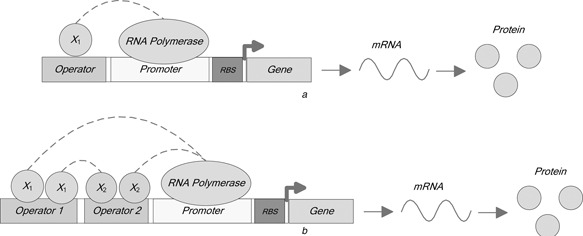
Overall framework of the bio‐gates
a Single TF
b Double TFs
The model with two TF protein inputs can be used to synthesise fundamental logic functions, including AND, OR, NAND, NOR and XOR. For these cases, a general promoter activity function is proposed as
| (14) |
where KR , K 1 and K 2 denote, respectively, the independent binding strength of RNAp and those of the regulators X = (X 1, X 2) with X 1 and X 2 denoting, respectively, concentrations of two regulator inputs; the constant R denotes RNAp concentration, and mi , ∀i are the extra exponential coefficients. In the numerator of (14), the first term represents RNAp binds to promoter, the second and third terms represent the regulators X 1 and X 2 bound to the respective operation sites shown as the blue circles and grey blocks in Fig. 2 b, and the final term represents the regulators X = (X 1, X 2) bound to the operation sites.
The dynamics of mass balances for the transcription and degradation processes can be modelled by the following equation
| (15) |
where for one TF protein input, the promoter activity function f i ( X ) is defined as
or the promoter activity function f 2 ( X ) for two TF protein inputs is defined as
where f r ( X ) refers to the transcriptional repression, f a ( X ) refers to the transcriptional activation, Xo is the concentration of TFo, the constant α is the maximal production of TFo and β is the degradation rate constant of TFo.
3.3 Transcription CRIF gates design
The RSGA is not only capable of searching unknown parameters but also able to search for the optimal system structure. In the application of the CRIF model design, a chromosome includes a set of control genes and parameter genes representing regulative parameters.
3.3.1 Structured genetic mapping for biological gates
In RSGA, the structured genetic mapping operation plays a central role to produce different structures of the model. The control genes govern the corresponding parameter genes based on the operation for structured mapping defined in (2).
For the biological logic gate with two TF protein inputs in (14), we regard all parameters as parameter genes and set the control genes, whose number equal to the number of structure coefficients, to control the corresponding extra exponential coefficients. If the cored coefficients are to be determined, the structured genetic mapping can be designed as
where c 1, c 2, c 3, c 4 are control genes that govern the changes of parameters m 1, m 2, m 3, m 4 for structured mapping, respectively. The control genes determine the parameter genes in ON/OFF status or linear scaling multiplication.
Randomly generate a chromosome with B max = 5 and B min = 0.1. If in a certain generation, the chromosome before mapping is of the following form
Conducting the structured genetic mapping yields
This chromosome model is designed in such a way that the first four control genes regulate the first four parameter genes. The remaining genes do not need to join in structured genetic mapping if they are not related to the solution structure. The off operation of the control genes regulate the related parameter genes, the cooperativity mi , to be a small number. In other words, it means that the effective cooperativity hi mi approaches to zero and the influence of the term can be ignored. After mapping, this chromosome represents a set of new parameters of a logic gate shown as follows
When mi is small enough to be ignored, the corresponding term loses its effect on the corresponding mRNA transcription. If mi ≠ 0, the term related to the synthesis (transcription) is activated with its power changed to mi hi ; hence alternates the sensitivity of transcription.
3.3.2 Fitness function
For evaluating the performance of each chromosome, the fitness function of the biological logic gate design is defined as the reciprocal of the objective function
| (16) |
The objective function J total is a multi‐objective assessment. It comprises two parts, Ja and Jd related, respectively, to the accuracy of logic values and sharpness of the contrast between high and low‐logic levels. Hence, J total is defined as
| (17) |
where ρ ∈ [0, 1] is the weighting factor representing the relative emphasis on Ja and Jd in which
| (18) |
and
| (19) |
Here (X 1, X 2) = (0, 0), (0, 1), (1, 0) and (1, 1), where ‘0’ refers to the low logic level and ‘1’ refers to the high logic level. When the difference between max(fi ) and min(fi ) is sharpen, Jd becomes small accordingly. High contrast between the report protein concentrations related to logic ‘0’ and logic ‘1’ implies good performance of the design.
3.4 Case study
In computational experiments of the proposed RSGA approach, we design the genetic regulatory logic gates to maximise the value of the fitness function. Some designs are compared with the transcription regulatory logic gates synthesised by neural network [19]. See Table 1 for the truth table of the experimental logic gates.
Table 1.
Truth table of various logic gates
| Input 1 | Input 2 |
|
|
AND | OR | NOR | NAND | XOR | ||
|---|---|---|---|---|---|---|---|---|---|---|
| 0 | 0 | 1 | 0 | 0 | 0 | 1 | 1 | 0 | ||
| 0 | 1 | 1 | 0 | 0 | 1 | 0 | 1 | 1 | ||
| 1 | 0 | 0 | 1 | 0 | 1 | 0 | 1 | 1 | ||
| 1 | 1 | 0 | 1 | 1 | 1 | 0 | 0 | 0 |
The total generation number is set to be 200; the population size is 400 and the weighting factor ρ is 0.6; R max and R min are set to be 5 and 0, respectively.
The optimally designed logic gates by the RSGA approach are obtained as follows: For the case of the promoter binding one TF, the bio‐CRIF models of NOT and Buffer logic gates are, respectively, obtained as
and
It is seen from the above two synthetic CRIF models that the logic gates NOT and Buffer exhibit the same topology but with different parameters shown as in Fig. 3 a. By regulating the binding strength, the logic NOT and Buffer can be realised separately.
Fig. 3.
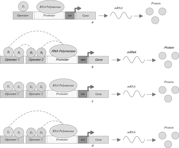
Frameworks for various bio‐gates
a NOT and Buffer
b AND and OR
c NOR and NAND
d XOR
As the role of buffer in electronics or telecommunications, which serves as an isolating circuit between two cascaded circuits for impedance matching, the Buffer here is to reshape the output level of a logic gate by enhancing the contract between logic ‘0’ and logic ‘1’ for better signal quality while connected to the next stage. In addition, it can improve the capability of noise rejection to avoid vagueness of the logic level due to the noise corruption.
For the case of the promoter binding two TFs, the bio‐CRIF models of AND, OR, NOR, NAND and XOR logic gates are obtained, respectively, as
and
From the above designed CRIF models for two‐input gates, it is seen that the logic AND and OR show the same topology but with different parameters shown as in Fig. 3 b. Fig. 3 c shows the topology of logic NOR and NAND. The topology of logic XOR is illustrated in Fig. 3 d.
For certain logic gate designs, the symmetrical output level between logic ‘0’ and logic ‘1’ might not be ensured while performing the evolutionary solution search. To remedy, an extra term can be incorporated into the objective function (18)
Fig. 4 illustrates output responses of the biological NOT, Buffer, AND and OR gates. Fig. 5 illustrates concentration of the reporter proteins of the biological NOR, NAND and XOR gates.
Fig. 4.
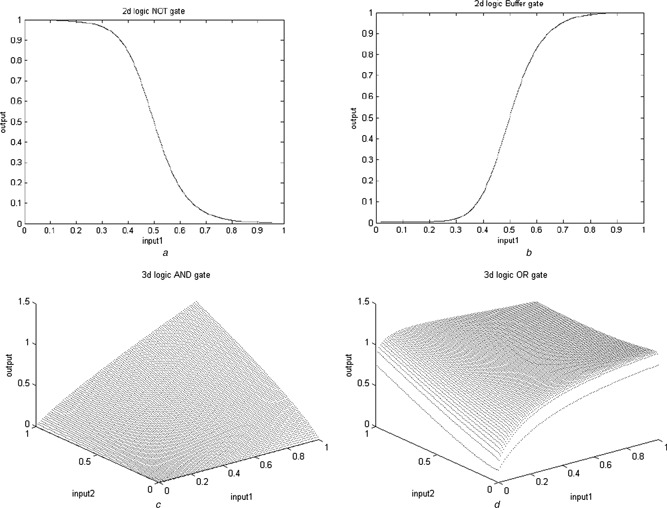
I/O responses of the bio‐gate designs based on the RSGA approach
a NOT
b Buffer
c AND
d OR
Fig. 5.
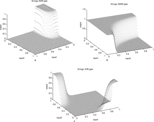
I/O responses of the bio‐gate designs based on the RSGA approach
a NOR
b NAND
c XOR
For comparison of the proposed design with those of the neural network approach [17], the representative edge curve of logic gate response based on various designs and a standard sigmoid curve are displayed in Figs. 6 and 7. Since the biological XOR exhibits unsymmetrical output response, we have compared the edge curve based on two perspectives in Fig. 7. The closer to the standard sigmoid curve obtains, the better one is obtained. To examine further, several two‐dimensional (2D) contour maps of the I/O responses of the logic gates are illustrated in Fig. 8. The single bar on the right indicates the magnitude of the output logic level. The effect of Buffer in reducing the logic status vagueness can be easily observed from these figures.
Fig. 6.
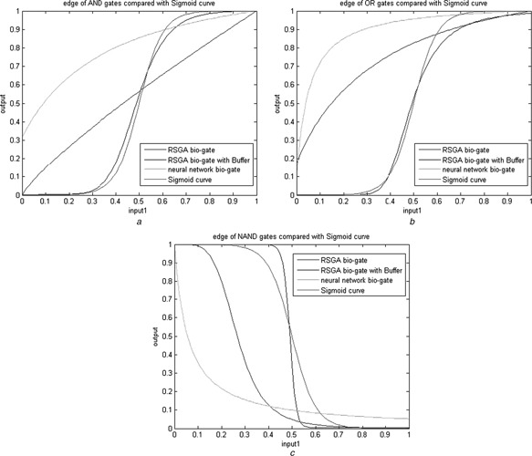
Side views of the bio‐gate responses based on various design approaches
a AND
b OR
c NAND
Fig. 7.
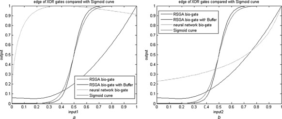
Side views of the XOR gate response based on various design approaches
a Output against input 1
b Output against input 2
Fig. 8.
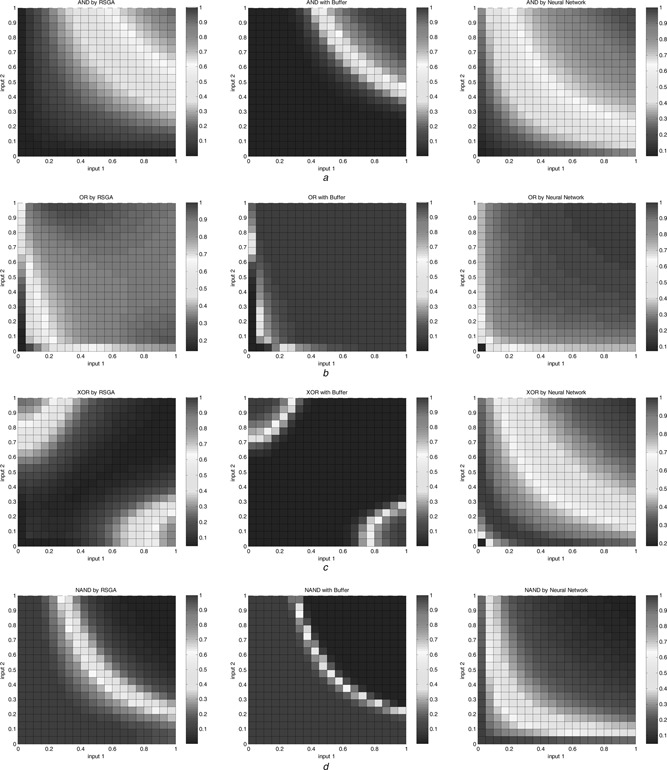
2D views of the bio‐gate responses based on various design approaches
a AND
b OR
c XOR
d NAND
The proposed approach shows its effectiveness in the sense that the proposed gate designs reveal less vagueness between high and low logic levels. The effect is more distinguishable when the gates are accompanied with Buffer.
4 Biological circuit design based on transcription gates
By using the transcription gates described above, it is possible to construct more complex biological circuits. In order to interconnect logic gates, the output of the last gate should be a TF protein served as an input to the next gate. Cascade connection of two gates is realised by choosing a suitable gene sequence as the last gate that encodes a protein acting as a TF to the next gate [14, 18]. In addition, selecting promoters experimentally is like replacing components in electric engineering. The promoter is turned on by TF and is used as the input to the next gate. An efficient way to deal with the task of biological circuit design is to build up a database of biological parts for proofreading and realising in vivo [15].
4.1 Combinational circuits
4.1.1 Full adder
The biological full adder considered here consists of two XOR gates, two AND gates and one OR gate as illustrated in Fig. 9 a. It executes binary add for two inputs A and B and one carry input denoted as C in. See Table 2 for the truth table, where S denotes sum and C denotes carry output. Fig. 9 b illustrates the steady‐state output response of the biological full adder realised via our proposed design. The waveform shows the exact response according to the rules established in Table 2.
Fig. 9.
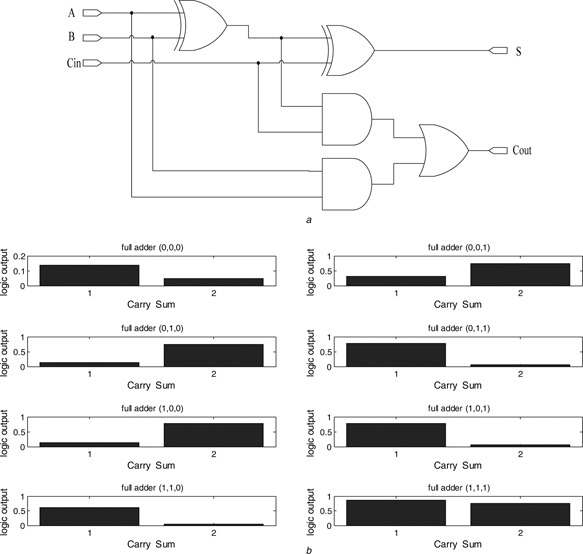
Biological full adder
a Cascade diagram of the biological full adder
b Measured steady‐state output response
Table 2.
Truth table of full adder
| Input 1 | Input 2 | Input carry | Carry | Sum |
|---|---|---|---|---|
| 0 | 0 | 0 | 0 | 0 |
| 0 | 0 | 1 | 0 | 1 |
| 0 | 1 | 0 | 0 | 1 |
| 0 | 1 | 1 | 1 | 0 |
| 1 | 0 | 0 | 0 | 1 |
| 1 | 0 | 1 | 1 | 0 |
A biological half adder can deal with a three‐input binary add operation. To extend it to the multiple stage ripple adder, the carry output C out of the full adder can be sequentially connected to the carry input C in of the next full adder.
4.1.2 Multiplexer (MUX)
A digital MUX, also called as a data selector, is a device that selects one of several digital input signals and forwards the selected input to the output port. A multiplexer of four inputs has two select lines (4‐to‐1 MUX) shown as in Fig. 10 a, with the corresponding truth table given in Table 3. The cascade diagram of the biological MUX, consisting of seven building bricks of two INV, four 3‐input AND gate and one 4‐input OR gate of building bricks is illustrated in Fig. 10 a. Figs. 10 b and c illustrate, respectively, the four input waveforms and the steady‐state reporter protein concentrations, with the MUX realised via the proposed biological logic gates.
Fig. 10.
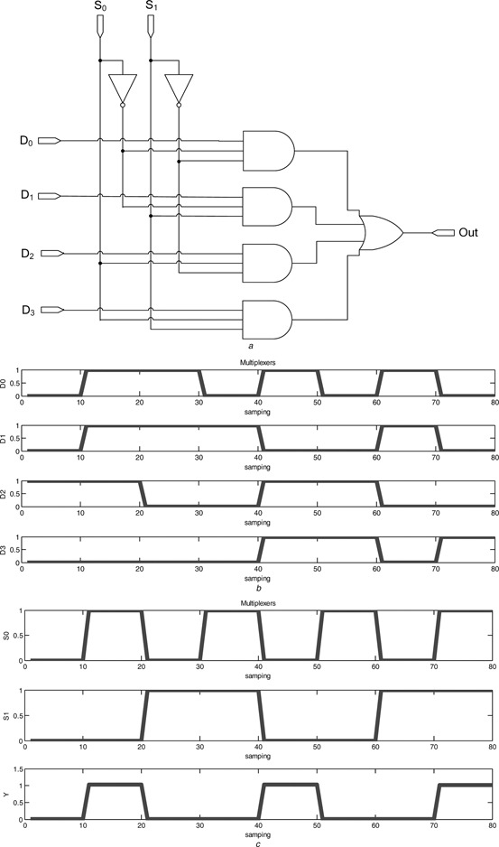
Multiplexer
a Cascade diagram of the biological MUX
b Input
c Output response
Table 3.
Truth table of MUX
| S 1 | S 0 | Input selected |
|---|---|---|
| 0 | 0 | D 0 |
| 0 | 1 | D 1 |
| 1 | 0 | D 2 |
| 1 | 1 | D 3 |
4.1.3 Arithmetic and logic unit (ALU)
Combining the functions of AND gate, OR gate, NOT gate, full adder and multiplexer developed above enables one to realise a biological ALU. An ALU forms a fundamental building brick of a transcription‐regular CPU with inputs Q 0, Q 1, Q 2 and Q 3 used to decode AND, OR, invert and sum operation, respectively, based on the inputs A and B. The 4‐to‐1 biological MUX works to select one of the four logic functions. The cascade diagram of building bricks is illustrated in Fig. 11 a. Fig. 11 b illustrates the steady‐state reporter protein concentration with the biological ALU being realised via combination of the proposed biological logic gates.
Fig. 11.
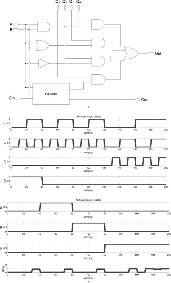
Arithmetic–logic unit
a Cascade diagram of the biological ALU
b Output response
4.2 Sequential logic circuits
4.2.1 J–K flip‐flop
The biological J –K flip‐flop consists of two NAND gates. The cascade diagram is illustrated in Fig. 12 a, with a three‐input NAND consisting of an AND gate and a NAND gate, as shown in Fig. 12 b. It is implemented in the biological sense as the circuit diagram illustrated in Fig. 12 c. The design is based on combination of the previously developed biological logic gates. The truth table is given in Table 4. Fig. 12 d illustrates the steady‐state reporter protein concentration of the biological J –K flip‐flop.
Fig. 12.
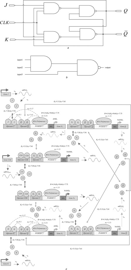
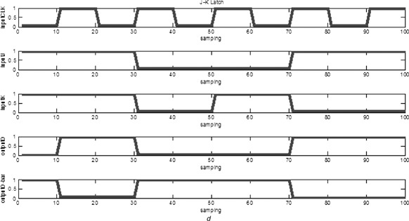
Biological J–K flip‐flop
a Cascade diagram of the biological J –K flip‐flop
b Three‐input NAND gate
c Circuit diagram
d Output response
Table 4.
Truth table of J –K flip‐flop
| J | K | CLK | Q |
|
Comments | |
|---|---|---|---|---|---|---|
| 0 | 0 | ↑ | Q 0 |
|
no change | |
| 0 | 1 | ↑ | 0 | 1 | latch RESET | |
| 1 | 0 | ↑ | 1 | 0 | latch SET | |
| 1 | 1 | ↑ |
|
Q 0 | toggle |
The biological J –K flip‐flop modifies the infeasible condition of a biological S –R latch. When both of the inputs J and K are logic ‘high’, the output Q becomes opposite. That is, if the output Q is originally at 0, it becomes 1 at the next state when triggered by clock input.
5 Discussions
Synthetic biology aims to construct the artificial biological circuits to implement the particular tasks or modify the behaviour of organisms by using the concepts of engineering circuit. This study has proposed a systematic strategy based on RSGA to synthesise the biological logic circuits, and then apply these basic logic circuits to assemble the combinational and sequential biologic circuits based on the topology of engineering theories. With the understanding of bio‐CRIF model of logic circuits, synthetic biologist can be easier to find suitable biological components from biological database for the construction of new biological logic circuits with complex functions. At present, it is still hard to realise a precise biological circuit with accuracy of its response up to two, or even less, decimal points. However, a biochemical network is very robust in responses because of the extremely slow dynamics. With these basic logic circuits, one can assemble more complicated combinational and sequential biological circuits from the viewpoint of bio‐engineers.
The ultimate goal of synthetic biology is to insert the designed logic circuits into host cell to perform a specific task. However, the crosstalk mechanisms in practical biological systems may be corrupted by some stochastic molecular disturbances, such as intrinsic and extrinsic noises, to affect the performance of the designed biological circuits. To solve this problem, one can further consider the effects of stochastic noises in the bio‐CRIF model. Moreover, the proposed combinational and sequential biologic circuits combine Buffers in each cascaded levels, and it can greatly decrease the decay of output signals before the input of next layer.
6 Conclusions
The RSGA approach has been proposed for the systematic design of a variety of synthetic biological logic gates and combinational circuits. The proposed approach is first applied to the design problem of biological logic gates and then extended to deal with the design problem for combinational biologic circuits and that for some sequential biologic circuits. A generalised bio‐CRIF model is constructed to model the biochemical reaction of basic biological logic gates. A multi‐objective function related to the performance and structure optimisation of logic gates is defined. The RSGA is used to determine the generalised promoter activity function for the targeted biological gates and circuits. By assembling fundamental biologic gates based on the topology of engineering circuits, we are able to implement almost all fundamental combinational and sequential biological circuits. The advantages of the resulting design have been well verified. It is shown that the proposed approach can achieve satisfactory performance with simple model structures for optimal design of the bio‐CRIF gates.
7 Acknowledgment
This research was sponsored by National Science Council, Taiwan, ROC, under the Grant NSC‐98‐2221‐E‐005‐087‐MY3.
8 References
- 1. Hasty J. McMillen D., and Collins J.J.: ‘Engineered gene circuits’, Nature, 2002, 420, pp. 224–230 (doi: 10.1038/nature01257) [DOI] [PubMed] [Google Scholar]
- 2. Dasika M.S., and Maranas C.D.: ‘OptCircuit: an optimization based method for computational design of genetic circuits’, BMC Syst. Biol., 2008, 2, (24), pp. 1–19 [DOI] [PMC free article] [PubMed] [Google Scholar]
- 3. Holland J.H.: ‘Adaptation in natural and artificial systems’ (MIT Press, Cambridge, MA, 1975) [Google Scholar]
- 4. Goldberg D.E.: ‘Real‐code genetic algorithms, virtual alphabets and blocking’, Compl. Syst., 1991, 5, pp. 139–16 [Google Scholar]
- 5. Dasgupta D., and McGregor D.R.: ‘A structured genetic algorithm: the model and the first result’. Rep. IKBS‐2–91, Strathclyde University, 1991. [Google Scholar]
- 6. Lai C.C., and Chang C.Y.: ‘A hierarchical genetic algorithm based approach for image segmentation’. Proc. IEEE Int. Conf. Networking, Sensing and Control, Taipei, 2004, pp. 1284–1288 [Google Scholar]
- 7. Tsai C.W. Huang C.H., and Lin C.L.: ‘Structure‐specified IIR filter and control design using real structured genetic algorithm’, Appl. Soft Comput., 2009, 9, pp. 1285–1295 (doi: 10.1016/j.asoc.2009.04.001) [DOI] [Google Scholar]
- 8. Tsai C.W. Lin C.L., and Huang C.H.: ‘Microbrushless DC motor control design based on real coded structural genetic algorithm’, IEEE/ASME Trans. Mech., 2011, 16, pp. 151–159 (doi: 10.1109/TMECH.2009.2037620) [DOI] [Google Scholar]
- 9. Wang B. Kitney R.I. Joly N., and Buck B.: ‘Engineering modular and orthogonal genetic logic gates for robust digital‐like synthetic biology’, Nat. Commun., 2011, 2, (508), pp. 1–9 [DOI] [PMC free article] [PubMed] [Google Scholar]
- 10. Anderson J.C. Voigt C.A., and Arkin A.P.: ‘Environmental signal integration by a modular AND gate’, Mol. Syst. Biol., 2007, 3, (133), pp. 1–8 [DOI] [PMC free article] [PubMed] [Google Scholar]
- 11. Privman V. Zhou J. Halámek J., and Katz E.: ‘Realization and properties of biochemical‐computing biocatalytic XOR gate based on signal change’, J. Phys. Chem. B, 2010, 114, (42), pp. 13601–13608 (doi: 10.1021/jp107562p) [DOI] [PubMed] [Google Scholar]
- 12. Halámek J. Bocharova V. Arugula M.A. Strack G. Privman V., and Katz E.: ‘Realization and properties of biochemical‐computing biocatalytic XOR gate based on enzyme inhibition by a substrate’, J. Phys. Chem. B, 2011, 115, (32), pp. 9838–9845 (doi: 10.1021/jp2041372) [DOI] [PubMed] [Google Scholar]
- 13. Vladimir P.: ‘Error‐control and digitalization concepts for chemical and biomolecular information processing systems’, J. Comput. Theor. Nanosci., 2011, 8, (3), pp. 490–502 (doi: 10.1166/jctn.2011.1714) [DOI] [Google Scholar]
- 14. Lauria M. Bhalerao K. Pugalanthiran M.M., and Yuan B.: ‘Building blocks of a biochemical CPU based on DNA transcription logic’. Workshop on Nonsilicon Computing, Munich, 2004. [Google Scholar]
- 15. Marchisio M.A., and Stelling J.: ‘Automatic design of digital synthetic gene circuits’, PLoS Comput. Biol., 2011, 7, (2), pp. 1–13 (doi: 10.1371/journal.pcbi.1001083) [DOI] [PMC free article] [PubMed] [Google Scholar]
- 16. Sayut D.J. Niu Y., and Sun L.H.: ‘Construction and enhancement of a minimal genetic AND logic gate’, Appl. Environ. Microbiol., 2009, 75, (3), pp. 637–642 (doi: 10.1128/AEM.01684-08) [DOI] [PMC free article] [PubMed] [Google Scholar]
- 17. Buchler N.E. Gerland U., and Hwa T.: ‘On schemes of combinatorial transcription logic’, Proc. Nat. Acad. Sci. USA, 2003, 100, (9), pp. 5136–5141 (doi: 10.1073/pnas.0930314100) [DOI] [PMC free article] [PubMed] [Google Scholar]
- 18. Tamsir A. Tabor J.J., and Voigt C.A.: ‘Robust multicellular computing using genetically encoded NOR gates and chemical wires’, Nature, 2011, 469, (7329), pp. 212–215 (doi: 10.1038/nature09565) [DOI] [PMC free article] [PubMed] [Google Scholar]
- 19. Bintu L. Buchler N.E., and Garcia H.G. et al.: ‘Transcriptional regulation by the numbers: models’, Curr. Opin. Genet. Dev., 2005, 15, (2), pp. 116–124 (doi: 10.1016/j.gde.2005.02.007) [DOI] [PMC free article] [PubMed] [Google Scholar]
- 20. Kaplan B. Bren A. Dekel E., and Alon U.: ‘The incoherent feed‐forward loop can generate non‐monotonic input functions for genes’, Mol. Syst. Biol., 2008, 4, (203), pp. 1–9 [DOI] [PMC free article] [PubMed] [Google Scholar]
- 21. Mayo A.E. Setty Y. Shavit S. Zaslaver A., and Alon U.: ‘Plasticity of the cis ‐regulatory input function of a gene’, PLoS Biol., 2006, 4, (4), pp. 555–561 (doi: 10.1371/journal.pbio.0040045) [DOI] [PMC free article] [PubMed] [Google Scholar]
- 22. Setty Y. Mayo A.E. Surette M.G., and Alon U.: ‘Detailed map of a cis ‐regulatory input function’, Proc. Nat. Acad. Sci. USA, 2003, 100, (13), pp. 7702–7707 (doi: 10.1073/pnas.1230759100) [DOI] [PMC free article] [PubMed] [Google Scholar]
- 23. Kinkhabwala A., and Guet C.C.: ‘Uncovering cis ‐regulatory codes using synthetic promoter shuffling’, PLoS ONE, 2008, 3, (4), pp. 1–10 (doi: 10.1371/journal.pone.0002030) [DOI] [PMC free article] [PubMed] [Google Scholar]
- 24. Zhang J. Yuan Z., and Zhou T.: ‘Combinatorial regulation: characteristics of dynamic correlations’, IET Syst. Biol., 2009, 3, (6), pp. 440–452 (doi: 10.1049/iet-syb.2009.0004) [DOI] [PubMed] [Google Scholar]
- 25. Chen A.M., and Zhou T.S.: ‘Sensitivity analysis of a cis‐regulatory input function’. Proc. Int. Symp. Optimization and Systems Biology, Lijiang, 2008, pp. 325–332 [Google Scholar]
- 26. Bintu L. Buchler N.E., and Garcia H.G. et al.: ‘Transcriptional regulation by the numbers: applications’, Curr. Opin. Genet. Dev., 2005, 15, (2), pp. 125–135 (doi: 10.1016/j.gde.2005.02.006) [DOI] [PMC free article] [PubMed] [Google Scholar]


