Abstract
Extracorporeal membrane oxygenation system is used for rescue treatment strategies for temporary cardiopulmonary function support to facilitate adequately oxygenated blood to return into the systemic and pulmonary circulation systems. Therefore, a servo flow regulator is used to adjust the roller motor speed, while support blood flow can match the sweep gas flow (GF) in a membrane oxygenator. A generalised regression neural network is designed as an estimator to automatically estimate the desired roller pump speed and control parameters. Then, the proportional–integral–derivative controller with tuning control parameters showed good performance to achieve speed regulation and speed tracking in the desired operating point. Given the pressure of carbon dioxide, drainage blood flow, and cannula size, the proposed predictable capability control scheme can be validated to meet the intended uses in clinical applications.
Inspec keywords: haemodynamics, three‐term control, medical control systems, patient treatment, neural nets
Other keywords: oxygen‐exchange blood flow regulation, extracorporeal membrane oxygenation system, rescue treatment strategies, temporary cardiopulmonary function support, roller motor speed, sweep gas flow, generalised regression neural network, proportional–integral–derivative controller, tuning control parameters, speed regulation, speed tracking
1 Introduction
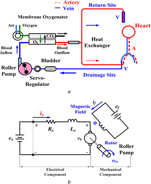
Extracorporeal membrane oxygenation (ECMO) system has three typical modes for temporary cardiopulmonary function support in adult and child patients, including venovenous (VV), venoarterial (VA), and veno‐VA (VVA) ECMO configurations, as shown in Fig. 1 a. Some surgical procedures, especially in neonatal cardiac surgery, ECMO is also a bridge to recovery tool for the immature heart. The VV ECMO configuration is the most commonly used mode for respiratory support in diseases such as acute respiratory distress syndrome and acute respiratory failure. This mode facilitates gas exchange, and blood is drained from the venous side into the ECMO machine and oxygenated blood returns into the systemic and pulmonary circulation systems. The VA ECMO is used to provide support for severe cardiac failures with/without associated respiratory failures, as blood is drained from the venous system and returned to the arterial system. Its configuration can provide continued and hemodynamic stabilisation, allowing patients recovering neurologic functions and clinicians time to make a therapeutic strategy. The VVA mode (VV be turned into VVA) or the VAV mode (VA be turned into VAV) is an upgraded method to improve recirculation [1, 2] and to provide well‐oxygenated blood to both systemic and pulmonary circulation systems [3, 4]. For the VV ECMO mode, near‐maximum blood flow rates, >4.0 l/min, are adequately maintained to optimise oxygen exchanges, which is equivalent to the patient's cardiac output. The VA ECMO configuration is a form of partial cardiopulmonary bypass and provides 60–80% of predicted cardiac outputs. The remaining of 20–40% of venous flows return into the pulmonary circulation [5]. Hence, blood flow is enough to provide the sufficient cardiac preload and maintain the left ventricular output at a mean blood pressure of >60 mmHg with 3.0–4.0 l/min and pump speed of >2500 rpm [6, 7]. The cardiac output is established using the centrifugal or roller pumps, which are commonly used in adult patients. The VVA/VAV can support the optimal setting for the drainage flow rate of 2.0–4.0 l/min, and the return flow between the venous route and the arterial route should be maintained at a ratio of 3:2 (venous: arterial) [2, 8].
Fig. 1.
ECMO system
(a) Hybrid configuration of the systemic and pulmonary circulation system, (b) Electric circuit of BLDC motor
The sizes and the lengths of the inserted cannula are determined by the intended uses, such as patient body surface areas, weights, insertion sites, and ECMO operating modes [3, 9]. Then, the maximum drainage blood flow can be determined. Clinically, the ECMO bypass circuit is used on critical patients for more than a few days and the generally accepted low risk period is around two weeks. If blood drainage is inadequate, the high negative pressure in the route can lead to red blood cell damage and the risk of hemolysis [10]. Thus, the roller pump needs to ensure the desired supporting blood flow by adjusting the servo flow regulator. Then, the membrane oxygenator is used to regulate the sweep GF to achieve the best gas exchanges. In addition, carbon dioxide (CO2) removal is determined by blood flow and sweep GF across the membrane oxygenator. Increasing both blood and GF can improve the pressure of carbon dioxide (PCO2) and pouvoir hydrogene (pH) in the arterial and venous blood. Due to CO2 diffuse faster than oxygen, the PCO2 is a variable index of CO2 removal from the membrane oxygenator. For the desired PCO2 depending on the patient's condition, high arterial PCO2 requires to increase the ECMO flow to achieve best possible oxygenation.
While a renew operation condition is determined by clinicians, a predictable capability controller is employed to automatically estimate the desired pump speed and control parameters. For keeping a long‐term baseline, the ECMO system should maintain sufficient drainage flow and track the desired setting point for meeting desired conditions on adult or child patients for a few days, such as drainage cannula sizes (CSs), drainage blood flows (BFs), and PCO2. The aim of study is intended to determine the suitability conditions for supporting sufficient drainage flow and hemodynamic stabilisation during several days. Therefore, a predictable capability control scheme with an intelligent estimator and a proportional–integral–derivative (PID) controller is used to automatically estimate the desired pump speed for fulfilling various conditions.
PID or proportional–integral (PI) controllers are being used in existing commercial ECMO control systems [11]. However, these controllers cannot automatically estimate the desired motor speeds to drive the extracorporeal flow and also require tuning of the optimal controller parameters to improve the control performances for fulfilling various conditions, including three parameters: P, I, and D gains. The desired operating points are determined by the clinically intended uses and surgeon experiences. In direct current (DC) motor and brushless DC (BLDC) motor controls, the PID/PI controller and the fuzzy logic based on self‐tuning methods and optimisation methods [12, 13, 14, 15, 16, 17] are used to determine the optimal control parameters to minimise overshoot, enhance setting time, and improve transient responses, such as particle swarm optimisation‐PID, fuzzy logic‐PID, evolutionary programming‐fuzzy control, and genetic algorithm‐PI [16, 17]. However, self‐tuning and optimisation methods are used only to tune the optimal control parameters without automatically estimating the desired operating points under various conditions. In addition, optimisation algorithm, inference rules, and look‐up table can determine the controller parameters; however, they cannot estimate the desired pump speed for meet a renew operation condition.
For pump speed estimation, we combine the generalised regression neural network (GRNN) [18, 19, 20, 21] and the PID controller to design a predictable capability control scheme for both speed regulation and speed tracking. The machine learning based GRNN method is used to model an estimator to map the non‐linear relationship between three input variables (PCO2, drainage BF, and drainage CS) and four response variables (three controller parameters and pump speed). Base on multiple linear regressions with three input and four output variables, a non‐linear model is considered to carry out an estimator. Input–output paired training data is used to train the GRNN‐based estimator from experimental data or clinical data and optimal control parameters. Then, the trained estimator can predict pump speed to overcome the trial‐and‐error design procedures. The Ziegler–Nicholas‐based [22, 23, 24] tuning method is used to select the three optimal control parameters to meet the speed ranges of 200–4000 rpm operating conditions. Thus, a tuned PID controller can minimise overshoot, improve transient responses, and eliminate steady‐state errors. While three desired input parameters are chosen, the GRNN is employed to estimate the pump speed and control parameters to maintain the rated ECMO flow. According to the desired pump speed, a buck‐boost converter (BBC) [25, 26, 27] quickly regulates the control signal using the PID controller to switch the duty ratio. Thus, speed regulation and tracking controls can be carried out to enhance the hemodynamic stabilisation, such as adequacy ECMO flows, gas exchange supports, and decreasing PCO2 in the accepted specific range. The proposed predictable capability control scheme can also be easily implemented in an embedded system.
The remainder of this paper is organised as follows: Section 2 addresses the methodology, including the BLDC motor model, the PID controller with the tuning method, the GRNN‐based estimator, and the proposed predictable capability control scheme. In Sections 3 and 4, respectively, the experimental results, discussion, and conclusions provide feasibility tests to validate the proposed control model.
2 Materials and methods
2.1 BLDC motor electromechanical model
A DC‐motor electromechanical model consists of electrical and mechanical components, as shown in Fig. 1 b. It can be used for robotic controls, electrical vehicles, and pump drives. A magnetic field, Φ, is produced by a stationary electromagnet. The BLDC motor has speed control capability, which implies that the speed, the torque, and the rotation directions can be easily changed to fulfil the new conditions. Since the flux, Φ, in the magnetic field is fixed constant, the speed–torque and current–torque characteristics are linear characteristics. Its absorbed power is supplied by a DC‐power source via a DC/AC inverter switching to AC three‐phase power source to drive the motor. The speed–torque characteristic is controlled by changing either the input voltage, ea or the electric resistance, Ra . Therefore, the speed, ωm , of a BLDC motor has linear control and has the relationship
| (1) |
where km is the electrical constant, and Ia is the armature current. The speed dynamics are obtained using the input voltage, ea (ea ∝ ωm ). Thus, supplying the input voltages, ea , to control the motor speed, a set of speed–torque characteristics can be obtained to match the load.
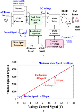
A pulse‐width modulation (PWM) mode (33.33 Hz/krpm) is a variable‐voltage–variable‐frequency method that regulates the input power to drive the BLDC motor [10]. The PWM method performs on or off power switching using the Hall effect frequency, as shown in Fig. 2 a. The output of the frequency‐to‐voltage (F–V) converter is adjusted with a calibration to 1000 rpm/V, as shown in Fig. 2 b. The speed control provides the specific scale from 0 to 4500 rpm with the control voltage signal, 0.0–4.5 V adjustment setting the motor speed [11]. Hence, the voltage signal can be estimated as
| (2) |
| (3) |
where Vm refers to the shaft speed, ω m , of the F–V converter and V ref refers to the desired speed, ωref, with the symbol ‘+’ indicating a step‐up voltage and the symbol ‘–’ indicating a step‐down voltage.
Fig. 2.
ECMO pump control system
(a) Block diagram of closed loop control for motor speed control, (b) Motor speed versus voltage control signal (1000 rpm/V)
The motor speed is determined from the applied DC voltage, ea = V out. A BBC is used to regulate the supplying voltage by switching the duty ratio, D [25, 26, 27]. The duty ratio of the control signal is defined as follows:
| (4) |
Buck mode,
| (5) |
Boost mode,
| (6) |
where T on is the turn‐on time, T off is the turn‐off time, and Td is the timing interval of each control signal; the duty ratio, D, is always positive and has a value < 1; and V rate is the rated input voltage (12 VDC in this study). The BLDC motor usually operates in the buck model via an AC/DC power source (30 VAC, 0.26 kW [11]) providing power for the ECMO system and battery charges. An uninterrupted power supply is provided in the boost mode. With the ‘closed loop control mode,’ the PID controller is used to manipulate the motor speed to fulfil the various dynamic responses.
2.2 Regulate duty ratio with PID controller
To regulate the duty ratio, a PID controller is used to step up or step down the output voltage of the BBC by varying the ±ΔD, as
| (7) |
| (8) |
It can continuously estimate the error signals, Δe (t) = |V ref − Vm (t)|, as the differences between the desired set point, V ref, and the estimated voltage, Vm (t), at the response time, t.
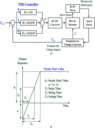
In this study, the regulation of the duty ratio using the PID controller‐based control scheme is shown in Fig. 3 a. The coefficients are the tuning parameters, which are tuned by the Ziegler–Nicholas tuning method [22, 23, 24]. According to the ideal step response curve, shown in Fig. 3 b, the rising time, T 2, is the time while the output response reaches 50% of the steady state value, with the derivative gain, KD = KP × (T 2 − T 1). The steady‐state error is removed using the integral gain action, K I = K P /k 1, where k 1 is the steady‐state value; and K P is the proportional gain. The designs of the controller parameters using the Ziegler–Nicholas step response method are shown in Table 1. The error signal, u (th ), can be represented as the discrete form
| (9) |
where Δt = th − th −1 is the response time, e (th ) and e (th −1) are the error signals, and h = 0, 1, 2, …. The advantage of the discrete PID controller can be easily implemented in a PC‐based application or an embedded system. Equation (9) will regulate the duty ratio of the BBC converter to change the input voltage, ea , in this study.
Fig. 3.
PID controller based control scheme
(a) Regulate the duty ratio with the PID controller to drive BLDC motor, (b) Ideal unit response curve of the close loop control
Table 1.
Controller parameter selections using Ziegler–Nicholas step response method
| Controller | Gain | ||
|---|---|---|---|
| K P | K I | K D | |
| P | k 1 /(2 × k 1) | — | — |
| P‐I | k 1 /(2 × k 1) | K P /k 1 | |
| P‐D | k 1 /(2 × k 1) | — | K P × (T 2 − T 1) |
| P‐I‐D | k 1 /(2 × k 1) | K P /k 1 | K P × (T 2 − T 1) |
2.3 GRNN‐based estimator
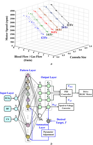
For temporary cardiac and respiratory function supports, adequate BF achieves the best possible oxygen exchange. Sufficient drainage venous CSs can determine the maximum supporting BF, 2.0–5.0 l/min for adult patients and 0.0–2.0 l/min for children, as seen in Fig. 4 a. In addition, the pressure of carbon dioxide (PCO2 = CO2 content × mmHg) is an important index of CO2 removal from the lungs. Carbon dioxide removal is determined by total surface area, BF, and sweep GF across the membrane oxygenator in an ECMO system. Increasing BF and GF can improve the partial PCO2 and the pH value in the arterial and venous blood. The specific range of partial PCO2 is [34 mmhg–46 mmHg] in the arterial blood, {39 mmhg–54 mmHg} in the venous blood, and pH value is {7.31–7.54} for all ages and females/males [28, 29]. Owing to CO2 be more soluble in blood, the PCO2 is a non‐linearity variable (depending on the patient's condition) of CO2 removal from the membrane oxygenator. Thus, CS, BF, and PCO2 are used to establish a non‐linearity estimator with three input variables to predict the motor speed and control parameters. An intelligent method (machine learning model) with multiple linear regressions is carried out to map the relationship between multiple input and output variables, such as parallel computing models and multilayer neural networks.
Fig. 4.
GRNN‐based estimator
(a) Training patterns: The motor speed (rpm) versus the blood flow/GF and CSs (12–22‐Fr), (b) GRNN‐based motor speed and control parameter estimator
In this study, a GRNN is a multilayer network with three inputs and four outputs that is carried out with a motor speed and control parameters (P, I, and D gain) estimator using the multiple regression method shown in Fig. 4 b. Its algorithm and with a gradient descent method can be summarised as follows [18, 19, 20]:
- Step 1: For each training pattern, xk = [x 1 (k), x 2 (k), x 3 (k)] = [CS(k), BF (k), PCO2 (k)] for k = 1, 2, 3, …, K, connecting weights, wki , i = 1, 2, 3, are created between the input layer (I) and the pattern layer (P) by
where W IP = [wki ]T is a K by three matrix; BF max and PCO2,max are the maximum values; BF is arranged in the specific range 2–5 l/min for an adult patient or 0–2 l/min for a child patient; PCO2 is arranged in the critical range 27–59 mmHg for artery/vein, all ages, and females/males [29]; and NCS is the number of drainage CSs, 12–22‐Fr. An extension into a high‐dimensional feature pattern is performed with non‐linear mapping from the three‐dimensional to a K ‐dimensional feature space.(10) - Step 2: Connecting weights, wkj , j = 1, 2, …, 5, are created between the pattern layer (P) and the summation layer (S) by
where ω max = 4500 rpm is the maximum motor speed, where connecting values are associated with the three inputs. The connecting weights from the overall pattern nodes to the summation nodes are set as 1, and W PS was a K by five matrix.(11) - Step 3: The output of the pattern node, Hk , k = 1, 2, …, K, is computed as a Gaussian function
where x = [x 1, x 2, x 3] is the testing pattern, smoothing parameters, σ = σ 1 = … = σk = … = σK, can be obtained by using the optimisation algorithm.(12) - Step 4: The outputs of node yj (k), j = 1, 2, …, 4, in the output layer are computed by
(13)
For a mean squared error function (MSEF), the gradient descent method is used to find the optimal parameter, σ, that is intended to minimise the objective function MSEF and to enhance the accuracy of the GRNN‐based estimator. The MSEF can be defined as
| (14) |
where Tj (k) is the desired target [K P (k), K I (k), K D (k), ω (k)/ω max] for the input variables, xk . The first partial derivatives of the MSEF are
| (15) |
| (16) |
| (17) |
Hence, the smoothing parameter,σ, is adjusted using the iteration computing, the so‐called ‘learning stage,’ as
| (18) |
where η is the learning rate, 0 < η ≤ 1, and p is the iteration number. When the objective function is less than a pre‐specified value, ε, then the learning stage is terminated. In the recalling stage, the trained GRNN‐based estimator is used to estimate the appropriate motor speed and control parameters for automatically operating the drainage BFs.
2.4 Predictable capability control scheme for ECMO supporting blood flow regulation
The proposed predictable capability control scheme for ECMO motor speed regulation is shown in Fig. 4. The GRNN‐based estimator was used to estimate the desired motor speed and control parameters. Considering the combinations of venous (V) and arterial (A) CSs (18–22‐Fr, 1‐Fr = 1/3 mm) for the drainage site (16–20‐Fr) for the return sites, the enrolled clinical data (Institutional Review Board of the National Cheng Kung University Hospital, under contract number A‐ER‐105‐125) were available ranges of the motor speed, 1600–4000 rpm, to drive the drainage BF, 2.0–5.0 l/min. In the cardiopulmonary bypass circuit, the membrane oxygenator is used to regulate sweep GF and then exchange gas, both oxygen and carbon dioxide, from the extracorporeal blood. Thus, the partial PCO2 and the pH value could be improved in the arterial and venous blood. In addition, the adequate drainage BF can also reduce the risks of blood cell damage and hemolysis. The predictable capability of motor speed estimator can determine the adequate drainage BF for fulfilling various conditions.
Considering a closed‐loop control configuration, a PID controller was designed to regulate the oxygen‐exchange blood flow for an ECMO pump control dynamic plant. The control parameters, KP , KI , and KD , were manipulated to accurately control motor speeds, while providing in the VV and VA ECMO modes. While the motor speed had a wide range, the variable‐voltage–variable‐frequency with the closed‐loop control could extend the available ranges. Using the Ziegler–Nicholas step response method [22, 23, 24], well‐controlled performances to fulfil various conditions. For the enrolled clinical data, the enabled speed range was 200–4000 rpm to drive 2.0–5.0 l/min BF for adult patients controller parameters were estimated for various speed ranges, as shown by the control parameter selections in Table 2. Hence, we can consider the pairs of training patterns from the enrolled clinical data as [CS (k), BF (k), PCO2 (k)] referring to [K P (k), K I (k), K D (k), ω (k)] that are used to design the GRNN‐based prediction model. The overall training patterns can be divided into two groups, referring to the enabled motor speed 1600–4000 rpm for adult patients and 200–1600 rpm for children, which can be applied for training the GRNN in the learning stage. The procedure of predictable capability control scheme for oxygen‐exchange blood flow regulation is shown in Fig. 5.
Table 2.
Control parameters selections using the Ziegler–Nicholas step response method
| Patient | Operation model | BF, l/min | Speed, rpm | K P | k 1 | K I | T 2 − T 1, s | K D |
|---|---|---|---|---|---|---|---|---|
| child | VV, VA | <2.0 | 200–1000 | 0.50 | 0.2–1.0 | 2.5000–0.5000 | 0.001 | 0.0005 |
| 1000–2000 | 0.50 | 1.0–2.0 | 0.5000–0.2500 | 0.001 | 0.0005 | |||
| adult | VA, VVA | 2.0–4.0 | 2000–3000 | 0.50 | 2.0–3.0 | 0.2500–0.1667 | 0.001 | 0.0005 |
| 3000–4000 | 0.50 | 3.0–4.0 | 0.1667–0.1250 | 0.002 | 0.0010 | |||
| VV | >4.0 | 4000–4500 | 0.50 | 4.0–4.5 | 0.1250–0.1111 | 0.002 | 0.0010 |
Fig. 5.
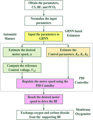
Flowchart of the proposed control scheme
3 Experimental results and discussion
3.1 GRNN‐based estimator training and testing
In this study, case studies in the VA ECMO configuration were chosen to validate the proposed control scheme. The VA mode provided full support for both the heart and lung functions, such as cardiogenic shock and acute myocardial infarction. The pathological process in the patient might be reversible or not, and could quickly provide continuous hemodynamic stabilisation for vital organ perfusion, a candidate for transplantation or myocardial recovery. The VA mode also decreased the cardiac work and reduced the cardiac oxygen consumption. In addition, the AV circuit, established from the artery to the vein, required a cardiac index of at least 2.5 l/min. Then, a flow meter was regulated to increase the sweep GF, resulting in decreasing the concentration of carbon dioxide and partial PCO2 in the blood. The VA mode provided 60% – 80% of the predicted resting cardiac output. The blood flow through the AV circuit was monitored to provide the sufficient preload and afterload by regulating the motor speed. Thus, when the static variable, drainage cannula size, was determined, the extracorporeal venous blood was exposed to fresh gas by exchanging O2 and CO2 for meeting the different operating points.
For the combinations of V and A CSs (18–22‐Fr, 1‐Fr = 1/3 mm) for the drainage site (16–20‐Fr) for the return sites, the enrolled clinical data (Institutional Review Board of the National Cheng Kung University Hospital, under contract number A‐ER‐105‐125) and the experimental data were available ranges of the motor speed, 1600–4000 rpm, to drive the drainage BFs, 2.0–5.0 l/min. Fig. 6 shows the operating ranges and characteristic curves for motor speeds versus BFs. A total of 32 input–output pairs of training patterns, [PCO2, BF, CS] → [ωdesire, K P, K I, K D], were applied to design the GRNN‐based estimator. With the convergent condition that MSEF = ε ≤ 10−2, the GRNN training stage learned quickly to adapt the training patterns created by updating the parameter σ. Its training stage could rapidly converge on the specific conditions in <50 iteration computing. It took an average of < 0.1 sec/stage of CPU time in each training stage. Then, the optimal parameter, σ = 0.0116, can guarantee to minimise the mean squared error, <10−3, as shown in Fig. 7 a.
Fig. 6.
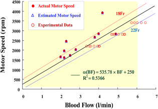
Operating ranges and characteristic curves for motor speeds versus BFs
Fig. 7.
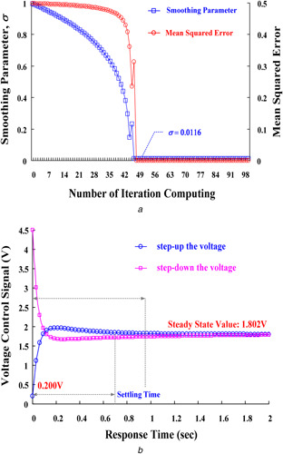
Training and testing results of GRNN‐based estimator
(a) Smoothing parameters and mean squared errors versus the number of iteration computing, (b) Control Response for step‐up/step‐down the voltage
In contrast with the proposed GRNN model, conventional neural network in a universal pattern mechanism has some problems, such as increasing size of training patterns are easy to fall into local minimum and need long time for training, and the number of neuron functions and computing processes are proportional to the complexity of the problems [21]. The GRNN is a kernel model with Gaussian distributions cantered on experimental scatter data for interpolation applications and multiple linear regressions, requiring a smaller sample size of training data than a conventional neural network [8]. The proposed model is a high‐dimensional pattern mechanism to deal with the non‐linear mapping applications. It is also guaranteed to converge to a universal prediction model using the gradient descent algorithm to adjust the kernel width. Therefore, it has self‐learning ability to deal with high‐dimensional data.
A total of six enrolled clinical data were chosen to validate the proposed control scheme, as seen related clinical data in Table 3 For a case study (no. 4, male patient), for establishing a VA ECMO circuit for heart surgery, one 20‐Frvenous cannula at the drainage site and one 20‐Fr arterial cannula at the return site were determined. The GRNN‐based estimator was used to determine the desired motor speed and control parameters with BF = 2.50 l/min, CS = 20‐Fr, and PCO2 = 29 mmHg. For supporting 2.50 l/min pump flow rate, the procedure of the proposed control scheme was summarised as follows:
Step 1: Input the BF, CS, and PCO2, then the predictable capability of GRNN‐based estimator was used to estimate the desired motor, ω = 1802 rpm, speed and control parameters, K P = 0.5000, K I = 0.2790, and K D = 0.0005, using (14) to (17), as seen in Table 3.
Step 2: Estimate the desired voltage control signal using (5), then V ref = 1.802 V can be obtained.
Step 3: Change voltages from an initial value 0.200 V to the desired value 1.802 V, ‘ΔV = + 1.602 V, means the step‐up the voltage by the buck mode.
Step 4: Estimate the desired duty ratio using (8), then D buck = 0.400.
Step 5: Regulate the BBC's output voltage by switching the duty ratio (33.33 Hz/krpm and 1000 rpm/V) using PID controller with the estimated control parameters, as shown in Fig. 8, then the V ref = 1.802 V and D buck = 0.400 can be achieved.
Table 3.
Enrolled clinical data for 6 subjects (IRB: A‐ER‐105–125)
| No. | CS‐Fr | BF, l/min | PCO2, mmHg | GF, 1/min | Blood pressure, mmHg | pH | SaO2, % | Pump speed, rpm | |
|---|---|---|---|---|---|---|---|---|---|
| Venous CS | Arterial CS | ||||||||
| 1 | 18 | 18 | 4.00 | 40 | 5.0 | 107 / 67 | 7.39 | 95 | 2845 |
| 2 | 20 | 18 | 3.80 | 48 | 5.0 | 103 / 51 | 7.37 | 98 | 2665 |
| 3 | 20 | 20 | 2.80 | 33 | 1.0 | 49 / 24 | 7.42 | 91 | 2025 |
| 4 | 20 | 18 | 2.50 | 29 | 3.0 | 95 / 59 | 7.30 | 91 | 1737 |
| 5 | 20 | 18 | 2.19 | 46 | 3.0 | 147 / 74 | 7.43 | 97 | 1617 |
| 6 | 22 | 20 | 2.20 | 32 | 8.0 | 67 / 64 | 6.85 | 99 | 1960 |
Fig. 8.
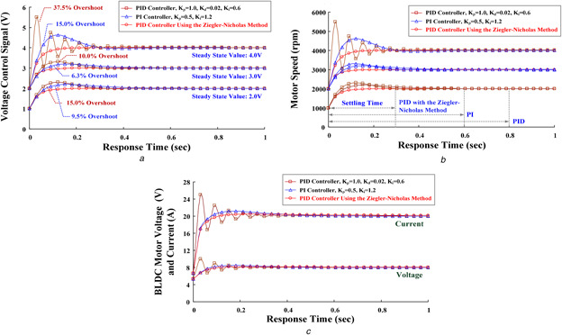
Control performances
(a) Voltage control signals versus response time, (b) Motor speeds versus response time, (c) BLDC motor input voltages and currents versus response time
For the step‐up voltage control signal, the PID controller was used to regulate the voltage and duty ratio until they reached the desired operating point. Conversely, the PID controller could also step down the voltage from the full scale to the operating point. It took about 0.7 and 1.0 s to achieve the steady‐state values (setting time), respectively, as shown in Fig. 7 b. Good control performances appeared in decreasing the overshoots, oscillations, and steady‐state errors. Therefore, the transient responses had hemodynamic stabilisation for supporting the blood flow in an atrioventricular or a VA circuit. Overall experimental results of six clinical cases are shown in Table 4.
Table 4.
Experimental results of clinical case studies
| No. | CS‐Fr, Venous | BF, l/min | PCO2, mmHg | Estimated control parameters | Pump speed, rpm | Error, %| | Voltage control, V | Duty ratio | |||
|---|---|---|---|---|---|---|---|---|---|---|---|
| K P | K I | K D | Actual | Estimated | |||||||
| 1 | 18 | 4.00 | 40 | 0.5000 | 0.1725 | 0.0010 | 2845 | 2917 | 2.53% | 2.917 | 0.642 |
| 2 | 20 | 3.80 | 48 | 0.5000 | 0.1876 | 0.0010 | 2665 | 2666 | 0.00% | 2.666 | 0.592 |
| 3 | 20 | 2.80 | 33 | 0.5000 | 0.2522 | 0.0005 | 2025 | 1989 | 1.78% | 1.989 | 0.442 |
| 4 | 20 | 2.50 | 29 | 0.5000 | 0.2790 | 0.0005 | 1737 | 1802 | 3.74% | 1.802 | 0.400 |
| 5 | 20 | 2.19 | 46 | 0.5000 | 0.3092 | 0.0005 | 1617 | 1617 | 0.00% | 1.617 | 0.359 |
| 6 | 22 | 2.20 | 32 | 0.5000 | 0.2561 | 0.0005 | 1960 | 1953 | 0.35% | 1.953 | 0.434 |
3.2 Control performance comparisons
The errors of voltage signals, Δe = (V ref − Vm ), were applied to the controller to determine the roller pump operating points based upon the instantaneous voltage, Vm , and the reference voltage, V ref. In this study, the PID and PI controllers with different control parameters were used to regulate the motor speed, as shown in Fig. 8. For example, a patient suffered from idiopathic severe pulmonary hypertension with right heart failure. He was inserted with one 18‐Fr cannula into his femoral vein and one 16‐Fr cannula into his femoral artery. The initial operating point was 2000 rpm; thus, the voltage control signal and duty ratio were 2.00 V and 0.44, respectively, for maintaining the operating point. However, the oxygen saturation was not optimal, especially for the upper body, and tapering FiO2 was difficult. Hence, one 16‐Fr cannula was inserted into his right internal jugular vein at the return site. Then, the clinicians decided to shift to the VVA mode under the blood flow of 4 l/min at the drainage site, in order to improve upper body saturation and lung tissue perfusion. Due to right heart failure, the VVA should support the optimal setting for the drainage flow rate of 4.0 l/min and the return flow between the venous route and the arterial route should be maintained at a ratio of 3:2 (venous: arterial) [2, 8]. While the motor speed increased from 2000 to 3000 rpm, the duty ratio regulation from 0.44 to 0.67 (control signal: 2.0–3.0 V) was used to step up the input voltage of the BLDC motor (rated voltage: ea = 12 VDC). Without selecting the suitable control parameters, it could be seen that the maximum per cent of the overshoot, 6.30%, was within the PI control response (KP = 0.50, KI = 0.60–1.20), as shown in Fig. 8 a. In addition, the PID controller without selecting the suitable parameters had >10.0% of the overshoot. Larger overshoot and oscillation responses would increase the setting time (>0.80 s) to achieve the steady‐state error, as shown in Fig. 8 b, and cause unstable motor speeds supporting the blood flow for oxygen exchange. After determining the desired setting point, the ECMO system should maintain sufficient drainage flow and avoid flow rate decreases. Hemodynamic stability can be followed by SaO2, PCO2, pH, blood pressure, and cardiac output, and cardiac recovery can be assessed by echocardiogram. This confirmed that the proposed model allowed the speed regulation and tracking control in supporting sufficient drainage flow in an ECMO system.
Based on the Ziegler–Nicholas method, the GRNN‐based estimator could learn and estimate the well‐controlled parameters (K P = 0.50, K I = 0.1667, K D = 0.0005) to meet the desired operating point. After the desired reference voltage is estimated, the PID controller with the tuning control parameters could minimise the overshoots and decrease the steady‐state errors from 1000 to 4000 rpm. It could also improve the transient responses such as degrading the transient‐state currents injection into the BLDC motor, as shown in Fig. 8 c. Hence, the transient larger currents surging into the motor during the transition power switching could be avoided. The setting time was <0.30 s to reach the steady‐state values. It required <10 switching cycles to reach the desired operating point and guaranteed to achieve the 0% steady‐state error.
4 Conclusion
The VA and VVA ECMO systems had good choices in the temporary cardiopulmonary function support for heart surgery or neurologic functions and myocardial recoveries. These ECMO circuits could meet patient's demands and also provided hemodynamic stabilisation for one or a few days in the intensive care unit. When the desired drainage cannulas, blood flow, and arterial/venous PCO2 were determined, the support driver was required by adjusting the pump motor. A good control response of the controller rapidly achieved the operating point and maintained the hemodynamic stabilisation. This study has proposed the use of a predictable capability control scheme integrating a GRNN‐based estimator and a PID controller to regulate the supporting blood flow. Therefore, extracorporeal blood flow can be adjusted or stabilised at a desired operating point to achieve the best oxygen exchanges in cases of acute cardiac failures with/without respiratory failures. The proposed control scheme has some advantages as follows: (i) the GRNN‐based estimator has an adaptive structure that can be created any time using the input–output pairs of current and new training patterns; (ii) the pattern mechanism can be modelled using the high‐dimensional/non‐linear input–output mapping function (3 × 32) → (32 × 34), to flexibly fit the enrolled data; (iii) the Ziegler–Nicholas method is used to select the control parameters for available speed ranges, 200–4500 rpm; (iv) the PID controller can enhance the transient responses in the step‐up and step‐down voltage controls, ± ΔV = ± 0.20 – ± 4.30, with the estimated control parameters; and (v) the proposed control scheme had a rapid response to reach the operating point and to maintain the hemodynamic stabilisation. The proposed predictable capability control model can also be easily implemented in a PC‐based application or an embedded system. In addition, it offers an innovative servo regulator for integration into existing ECMO control systems.
5 Acknowledgment
This study was supported and conducted by the Heart Science and Medical Device Research Center at National Cheng Kung University, in addition, this study is supported in part by the Ministry of Science and Technology, Taiwan, under contract number: MOST 102‐2314‐B‐006‐MY3 and MOST 105‐2221‐E‐244‐008, duration: August 1 2014–July 31 2017.
The authors declare that there is no conflict of interests regarding the publication of this paper. The Institutional Review Board (IRB) of the National Cheng Kung University Hospital, under contract IRB number: A‐ER‐105‐125.
6 References
- 1. Bonacchi M. Harmelin G. Peris A. et al.: ‘A novel strategy to improve systemic oxyge‐nation in venovenous extracorporeal membrane oxygenation: the X configuration ’, J. Thoracic Cardiovasc. Surg., 2011, 142, (5), pp. 1197–1204 [DOI] [PubMed] [Google Scholar]
- 2. Lindstrom S.J. Mennen M.T. Rosenfeldt F.L. et al.: ‘Veno‐right ventricular cannulation reduces recirculation in extracorporeal membrane oxygenation ’, Perfusion, 2012, 27, (6), pp. 464–469 [DOI] [PubMed] [Google Scholar]
- 3. Stohr F. Emmert M.Y. Lachat M.L. et al.: ‘Extracorporeal membrane oxygenation for acute respiratory distress syndrome: is the configuration mode an important predictor for the outcome? ’, Inter. CardioVasc. Thoracic Surg., 2011, 12, pp. 676–680 [DOI] [PubMed] [Google Scholar]
- 4. Choi J.H. Kim S.W. Kim Y.U. et al.: ‘Application of veno‐arterial‐venous extracorporeal membrane oxygenation in differential hypoxia ’, Multidiscip. Respiratory Med., 2014, 9, (55), pp. 1–5 [DOI] [PMC free article] [PubMed] [Google Scholar]
- 5. Chung M. Shiloh A.L. Carlese A.: ‘Monitoring of the adult on venoarterial extracorporeal membrane oxygenation’ Sci. World J., 2014, 2014, pp. 1–10, article id 393258 [DOI] [PMC free article] [PubMed] [Google Scholar]
- 6. Lee J.J. Hwang S.M. Ko J.H. et al.: ‘Efficacy of veno‐venous extracorporeal membrane oxygenation in severe acute respiratory failure ’, Yonsei Med. J., 2015, 56, (1), pp. 212–219 [DOI] [PMC free article] [PubMed] [Google Scholar]
- 7. Broman M. Frenckner B. Bjallmark A. et al.: ‘Recirculation during veno‐venous extra‐corporeal membrane oxygenation – a simulation study ’, Int. J. Artif. Organs, 2015, 38, (1), pp. 23–30 [DOI] [PubMed] [Google Scholar]
- 8. Kan C.D. Chen W.L. Lin C.H. et al.: ‘Optimal flow adjustment of veno‐venoarterial extracorporeal membrane oxygenation with an adaptive prediction model: cannula sizes screening and pump speeds estimation ’, IET Sci. Meas. Technol., 2016, 10, (3), pp. 177–184 [Google Scholar]
- 9. Martinez G. Vuylsteke A.: ‘Extracorporeal membrane oxygenation in adults, Continuing Education in Anaesthesia ’, Crit. Care Pain, 2012, 12, (2), pp. 57–61 [Google Scholar]
- 10. Frenckner B. Radell P.: ‘Respiratory failure and extracorporeal membrane oxygenation ’, Semin. Pediatric Surg., 2008, 17, pp. 34–41 [DOI] [PubMed] [Google Scholar]
- 11. Medtronic : ‘Bio‐Console® 560 ’. 2006, Extracorporeal Blood Pumping, Service Manual
- 12. Kuo C.L.: ‘Design of an adaptive Fuzzy sliding‐mode controller for chaos synchronization ’, Int. J. Nonlinear Sci. Numer. Simul., 2007, 8, (4), pp. 631–636 [Google Scholar]
- 13. Li T.H. Kuo C.L. Guo N.R.: ‘Design of an EP‐based fuzzy sliding‐mode control for a magnetic ball suspension system ’, Chaos Solitons Fractals, 2007, 33, (5), pp. 1523–1531 [Google Scholar]
- 14. Krishnn P.H. Arjun M.: ‘Control BLDC motor based on adaptive fuzzy logic PID controller ’. 2014 Int. Conf. on Green Computing Communication and Electrical Engineering, 2014.
- 15. Anitha E. Variaprakash P.: ‘Design of dynamic states and digital speed control of BLDC motor ’. 2016 Int. Conf. on Circuit, Power, and Computing Technologies, 2016.
- 16. Chen G.Y. Perng J.W. Ma L.‐S.: ‘DSP based BLD motor controller design with auto tuning PSO‐PID algorithm ’. 2015 IEEE/SICE Int. Symp. on System Integration, 2015.
- 17. Arulmozhiyal R.: ‘Design and implementation of fuzzy PID controller for BLDC motor using FPGA ’. 2012 Int. Conf. on Power Electronics, Drives and Energy Systems, 2012.
- 18. Specht D.F.: ‘A general regression neural network ’, IEEE Trans. Neural Netw., 1991, 2, (6), pp. 568–576 [DOI] [PubMed] [Google Scholar]
- 19. Wu J.X. Lin C.H. Du Y.C. et al.: ‘Sprott chaos synchronization classifier for diabetic foot peripheral vascular occlusive disease estimation ’, IET Sci. Meas. Technol., 2012, 6, (6), pp. 533–540 [Google Scholar]
- 20. Du Y.C. Chen W.L. Lin C.H. et al.: ‘Residual stenosis estimation of arteriovenous graft using a dual‐channel phonoangiography with fractional‐order features ’, IEEE J. Biomed. Health Inf., 2015, 19, (2), pp. 590–600 [DOI] [PubMed] [Google Scholar]
- 21. Li H. Ding S.: ‘Research and development of granular neural networks ’, Appl. Math. Inf. Sci., 2013, 7, (3), pp. 1251–1261 [Google Scholar]
- 22. Ziegler J.G. Nichols N.B.: ‘Optimum settings for automatic controllers ’, Trans. ASME, 1942, 64, pp. 759–768 [Google Scholar]
- 23. Singhal R. Padhee S. Kaur G.: ‘Design of fractional order PID controller for speed control of dc motor ’, Int. J. Sci. Res. Pub., 2012, 2, (6), pp. 1–8 [Google Scholar]
- 24. Meza J.L. Santibaenz V. Soto R. et al.: ‘Fuzzy self tuning PID semi global regulator for robot manipulators ’, IEEE Trans. Ind. Electron., 2012, 59, pp. 2391–2401 [Google Scholar]
- 25. TEXAS Instruments : ‘Design calculations for buck‐boost converters ’. Application Report, SLVA535A, August 2012
- 26. Sahu B. Rincón‐Mora G.A.: ‘A high efficiency, dual mode, dynamic, buck‐boost power supply IC for portable applications ’. 18th Int. Conf. on VLSI Design, 2005, pp. 858–861
- 27. Agostinelli M. Priewasser R. Marsili S. et al.: ‘Fixed‐frequency pseudo sliding mode control for buck‐boost DC‐DC converter in mobile applications: a comparison with a linear PID controller ’. 2011 IEEE Int. Symp. on Circuits and Systems, 2011, pp. 1604–1607
- 28. Allen S. Holena D. McCunn M. et al.: ‘A review of fundamental principles and evidence base in the use of extracorporeal membrane oxygenation (ECMO) in critically III adult patients ’, J. Intensive Care Med., 2011, 26, (1), pp. 13–26 [DOI] [PubMed] [Google Scholar]
- 29.Pediatric blood gases, critical care panel and ECMO‐Legacy Health. Available at https://www.legacyhealth.org


