

Abstract
In the past decade, acoustics at the nanoscale (i.e., nanoacoustics) has evolved rapidly with continuous and substantial expansion of capabilities and refinement of techniques. Motivated by research innovations in the last decade, for the first time, recent advancements of acoustics-associated nanomaterials/nanostructures and nanodevices for different applications are outlined in this comprehensive review, which is written in two parts. As part I of this two part review, firstly, active and passive nanomaterials and nanostructures for acoustics are presented. Following that, representative applications of nanoacoustics including material property characterization, nanomaterial/nanostructure manipulation, and sensing, are discussed in detail. Finally, a summary is presented with point of views on the current challenges and potential solutions in this burgeoning field.
Keywords: acoustics, nanotechnology, nanoacoustics, nanomaterials, nanostructures, acoustic microscopy, manipulation, sensing
1. Introduction
Sound is a mechanical vibration that propagates as acoustic waves in an elastic medium including air, liquid or solid structures. Acoustics is an interdisciplinary science that studies sound, particularly its production, transmission, and effects. Sounds with frequencies above the upper limit of human hearing range (typically 20 kHz) are termed as ultrasound [1].
Ultrasound is usually generated using a suitable transducer which converts electrical energy or other form of energy to acoustic energy [2]. Most of ultrasonic transducers use piezoelectric materials to generate acoustic waves from an alternating electric field using the converse piezoelectric effect. The same transducer can also be used to receive ultrasonic waves using the direct piezoelectric effect.
The first large scale implementation of ultrasound was in the military field near the beginning of World War I (1914) with the introduction of the first underwater sound navigation and ranging system (known as SONAR) [3], which was based on a pulse-echo operation. In the years that followed, many new applications for ultrasound were developed, inspiring the development of new technological advances. In the 1930s, ultrasound was introduced to generate heat to warm the deep tissue in the body, as a means of physical therapy [1]. In the late 1940s, in order to reduce the dependence of radiative medical X-ray imaging, ultrasonic pulse-echo imaging method was developed and applied to diagnostic medicine [3]. In the 1950s, Fellinger and Schmid successfully utilized ultrasound irradiation to promote hydrocortisone ointment delivery into the inflamed tissues for polyarthritis treatment [4]. Since then, the field of diagnostic and therapeutic ultrasound, i.e., medical ultrasound, has become one of the most active research fields and numerous outstanding breakthroughs have been reported. Due to its merits including easy-to-use, low cost, noninvasive assessment as well as no ionizing radiation, ultrasound imaging has been widely and actively used in the areas of gynecology, gastroenterology, angiology, and cardiology [5–9]. Moreover, ultrasound has been applied to promote drug or gene delivery into targeted tissues, including, but not limited to, skin, endothelium, and brain [10]. It has also been applied in treatment of various types of diseases, such as cancer, thromboembolism, and arteriosclerosis [11–14]. Beyond medical applications, ultrasound has also been used for many industrial applications, including ultrasonic cleaning, welding and processing, as well as non-destructive testing [15–22].
In the early 1980s, nanotechnology and nanoscience started to receive great attention from broad segments of the research community [23]. Nanotechnology is by its nature a highly multidisciplinary collection of fields, which involves chemistry, biology, materials, physics, and medicine. The breakthroughs and advances in nanotechnology have provided various nanoscaled materials and devices with extraordinary characteristics for ultrasound investigations [24–28]. In many ways, the combination of nanotechnology with ultrasonics has revolutionized conventional approaches to use ultrasound. The emergence of different nanomaterials for the support of diagnosis and treatment of numerous kinds of diseases has attracted increasingly more attention over the past few years and has now become an important field of medical ultrasound. Indeed, nanotechnology offers numerous emerging ultrasonic instruments, from lab-on-a-chip devices capable of monitoring and controlling nanoparticles, molecules, and individual cells, to nanoscaled probes for materials properties characterization.
Motivated by the research innovations over the last decade, this review, written in two parts, comprehensively examines, for the first time, recent advancements in the study of acoustics-associated nanomaterials/nanostructures and nanodevices for various applications, as summarized in Figure 1. Time and space do not permit us to review all the nanotechnology innovations that have been introduced into ultrasound during the past decade. Instead, the focus will be on the nanomaterials and nanostructures for acoustics, acoustic devices including acoustic sensors, actuators, and transducers involving nanomaterials and nanostructures, as well as nanoacoustic applications including characterization of materials and structures, nanomaterials/structures manipulation, sensing, biomedical imaging, and therapy.
Figure 1.
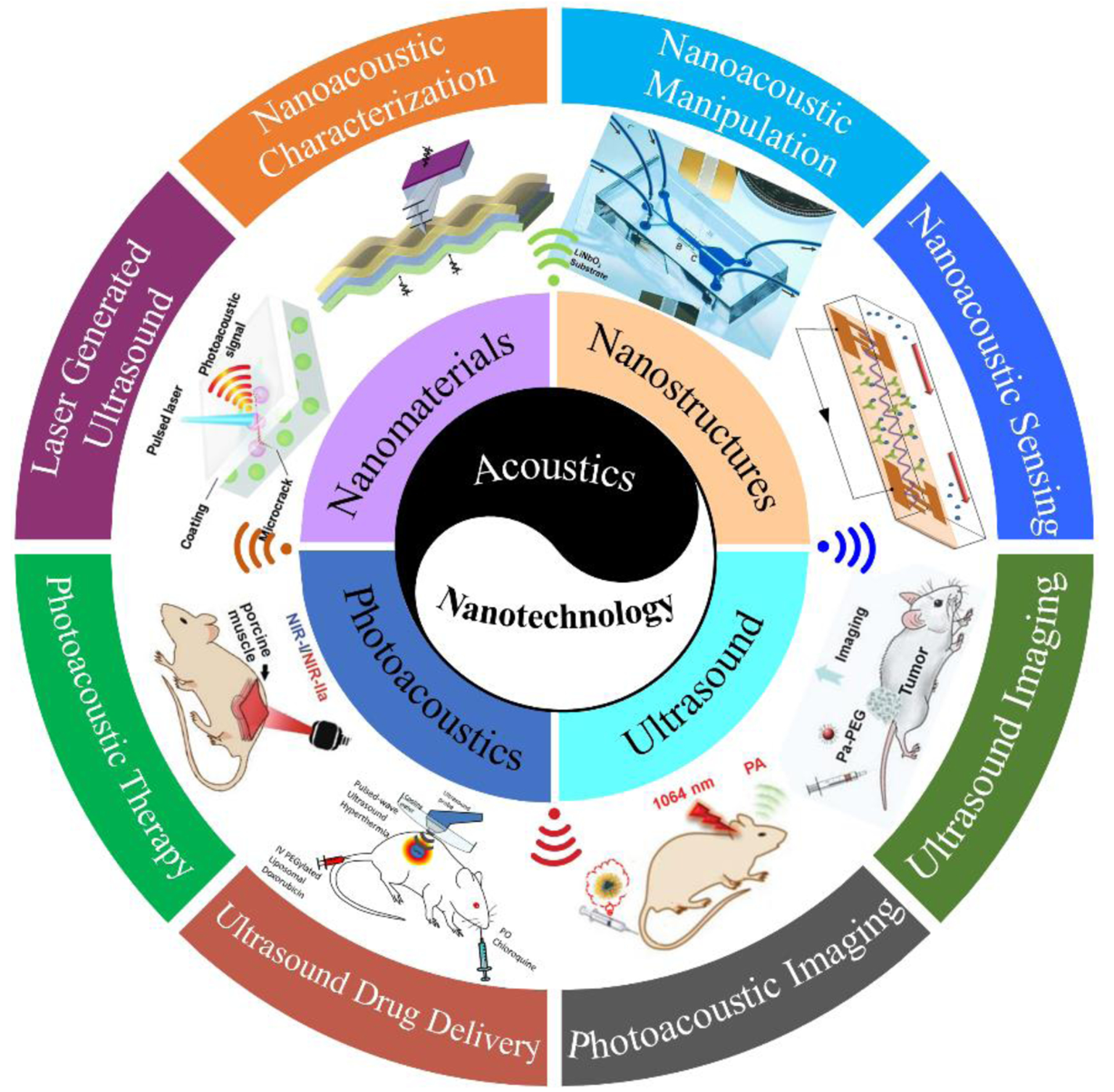
Schematic illustration of integration of acoustics-associated
nanomaterials/nanostructures and nanodevices for applications in this review. “Laser generated ultrasound”, Reproduced with permission [29]. Copyright 2018, American Chemical Society. “Nanoacoustic characterization”, Reproduced with permission [30]. Copyright 2017, American Chemical Society. “Nanoacoustic manipulation”, Reproduced with permission [31]. Copyright 2014, National Academy of Sciences. “Nanoacoustic sensing”, Reproduced with permission [32]. Copyright 2019, Elsevier. “Ultrasound imaging”, Reproduced with permission [33]. Copyright 2020, Ivyspring International Publisher. “Photoacoustic imaging”, Reproduced with permission [34]. Copyright 2019, Wiley-VCH. “Ultrasound drug delivery”, Reproduced with permission [35]. Copyright 2017, Dove Press Ltd. “Photoacoustic therapy”, Reproduced with permission [36]. Copyright 2020, Springer Nature.
As part I of this two-part review, this paper proceeds as follows: in Section 2, active and passive nanomaterials for acoustics will be reviewed in terms of their nanostructures and performances. In Section 3, nanoacoustics for characterization of materials and structures, nanomaterials/structures manipulation, and sensing, will be reviewed focusing on materials, devices, and applications. The last section (Section 4) provides a summary and outlook for research on nanoacoustics.
2. Nanomaterials and nanostructures for nanoacoustics
2.1. Active nanomaterials for acoustics
Due to their superior piezoelectric properties and excellent mechanical properties, one dimensional piezoelectric nanomaterials (e.g. one physical dimension out of nanoscale and the other two dimensions in the nanoscale) have been reported by researchers for acoustics, as summarized in Table 1. They consist of lead zirconate titanate (PZT) and polyvinylidene difluoride (PVDF) nanofibers that are applied for acoustic to electric energy conversion. For example, Chen et al. [37] developed PZT nanofiber composites with Au/Cr interdigitated electrodes for acoustic emission detection. The nanofibers were fabricated by employing the electrospinning method, illustrating high piezoelectric constant and mechanical strength. Compared with bulk PZT (0.025 Vm/N) and PZT microfiber (0.059 Vm/N), the g33 value of PZT nanofiber (0.079 Vm/N) was much larger, resulting in a higher sensitivity for acoustic sensing. PVDF-based nanostructures have also been widely used as piezoelectric active materials due to their high piezoelectric coefficient and high energy conversion efficiency. Sun et al. [38] fabricated composite PVDF nanofibers with zinc oxide (ZnO) nanorods to enhance the performance of PVDF-based nanofibers for acoustic vibration detection. The PVDF-ZnO composite nanofiber membranes were synthesized by electrospinning combined with hydrothermal method. The nanofiber membranes showed good acoustic-electric conversion properties under low frequency (< 1000 Hz) sound conditions. Compared with PVDF nanofibers at the same sound condition (140 Hz, 116 dB), the composite nanofibers demonstrated three times higher voltage output, which was mainly attributed to the enhanced piezoelectric coefficient of the hybrid nanostructures with ZnO nanorods.
Table 1.
The recently reported active nanomaterials for acoustics.
| Material | Fabrication method | Diameter | Application |
|---|---|---|---|
| PZT nanofiber [37] | Electrospinning | ~ 80 nm | Acoustic emission detection |
| PZT nanofiber [39] | Electrospinning | 50–120 nm | Acoustic emission detection and structural health monitoring |
| PVDF nanofiber [40] | Electrospinning | 310 nm | Noise detection |
| PVDF-ZnO nanofiber [38] | Electrospinning and hydrothermal | 90–140 nm | Acoustic vibration detection |
| PZT nanofiber [41] | Electrospinning | 200 nm | Acoustic vibration detection |
2.2. Passive nanomaterials for acoustics
Contrary to active nanomaterials for acoustics that can produce an electrical field when acoustic waves hit them, or can generate acoustic waves under an electrical or magnetic field, passive nanomaterials for acoustics mainly consist of nanoscaled materials assisting acoustic generation/detection as well as interacting with acoustic waves for various applications. They can be categorized into two types: organic nanomaterials (such as organic molecules and semiconducting nanomaterials) and inorganic nanomaterials (such as metallic nanoparticles, metallic nano-patterns, and carbon-based nanomaterials). The thorough review of those types of passive nanomaterials is presented in the following sections corresponding to the different applications. In this section, only the passive nanomaterials for electrode and laser-generated ultrasound are examined.
2.2.1. Nanoelectrode for acoustics
2.2.1.1. Nano-patterned electrode for piezoelectric materials.
Relaxor ferroelectric single crystals, particularly the lead magnesium niobate–lead titanate (PMN-PT), have been exploited for a great variety of applications including sensors, ultrasound transducers, and actuators due to their outstanding piezoelectric and dielectric properties [42,43]. The researches related to the properties of relaxor ferroelectric materials have been carried out for about two decades, and now it is widely recognized that the piezoelectric and dielectric properties of a ferroelectric single crystal are closely associated with its domain structures [44]. In order to further improve the properties of ferroelectric single crystals, domain engineering techniques have been employed by researcher. Patterning nanocomposite electrode, a kind of domain engineering techniques, has been effectively utilized for tailoring the piezoelectric and dielectric properties of ferroelectric materials over the past few years. Chang et al. [45] fabricated manganese (Mn)/gold (Au) composite nanopattern as nanoelectrode on a PMN-PT single crystal surface by using interference lithography method. Combined the Mn/Au nanoelectrode with back switching poling method, the [001] poled PMN-PT single crystal achieved the increase of piezoelectric coefficient d33 and dielectric constant by 27% and 25%, respectively. Following that work, in order to explore the relationship between the domain structures and the properties of the PMN-PT with nanoelectrode, the authors employed piezoresponse force microscopy and time-of-flight secondary ion mass spectrometry to study a PMN-PT sample with MnOx/Au nanocomposite electrode [46] (Figure 2a). Their results showed that the single crystal with the patterned nanoelectrode had a d33 36.7% higher and dielectric constant 38.3% higher than the crystal with conventional planar Au electrode. The increased piezoelectric and dielectric properties were attributed to Mn diffusion and doping as well as the fringe effect underneath the edge of the patterned nanoelectrode. Furthermore, Gao et al. [47] employed X-ray diffraction reciprocal space mapping technique to investigate how the patterned nanoelectrode affected domain distribution near the surface region under electric field. It was found that the enhanced properties were mainly attributed to the excess elastic energy stored in the nano domain distribution. Recently, Luo et al. [48] further advanced the study of domain morphology of PMT-PT with patterned nanoelectrode. They found that the domain morphologies varied from the nanoelectrode surface to the crystal interior. Compared with the crystal with planar electrode, the domain wall density of the crystal with nanoelectrode was higher. Moreover, the M phase of the nanoelectrode patterned crystal had higher randomness than that of the planar electrode deposited crystal.
Figure 2.

Nanoelectrodes for acoustics. (a) MnOx nanoelectrode patterned on a PMN-PT single crystal surface. Reproduced with permission [46]. Copyright 2018, Elsevier. (b) SEM images of the silver nanowires. Reproduced with permission [49]. Copyright 2021, IEEE.
2.2.1.2. Silver nanowire electrode for ultrasound transducers.
Conventionally, ultrasound transducers are always fabricated with a rigid structure, which cannot maintain a good coupling with the non-planar surfaces, such as human body or human skull, during different applications. The air gaps between the transducer and non-planar surface interface resulting from the poor coupling will lead to ~100% acoustic wave reflection and distortion, thus bringing about unreliable results. Recently, a flexible piezoelectric 1–3 composite structure was developed by Jiang et al. [50,51], which was composed of piezoelectric ceramic and soft elastomer polydimethylsiloxane (PDMS). Because traditional metal-based electrode could not be utilized for continuous bending, a highly stretchable and conductive silver nanowire-based electrode was fabricated for the flexible transducer (Figure 2b). The silver nanowires were synthesized by a modified polyol reduction technique [51]. They were randomly oriented to form a dense network on the transducer surface, having an average diameter of ~ 90 nm. Recently, the flexible piezo-composite ultrasound transducer deposited with the silver nanowire-based electrodes has been successfully applied for noninvasive blood pressure sensing applications [8,49].
2.2.2. Nanomaterials for laser-generated ultrasound
2.2.2.1. Photoacoustic effect.
The photoacoustic effect, discovered by Alexander Graham Bell in 1880, refers to the generation of acoustic waves from an object being irradiated by pulsed or intensity-modulated light [52]. While there are five main mechanisms responsible for the generation of photoacoustic signal, including dielectric breakdown [53], vaporization or material ablation [54], thermoelastic process [55,56], electrostriction [57], and the radiation pressure [58], for the majority of applications, thermoelastic expansion is the most commonly recognized mechanism for photoacoustic generation and is used widely for biomedical therapy, biomedical imaging, nondestructive inspection, and material characterization. The fundamental principle of thermoelastic generation of acoustic waves can be simply described as illustrated in Figure 3a [52]. When an optical illumination encounters a certain substance, part of the optical energy is absorbed by the substance and converted to heat energy. Therefore, the temperature of the object rises, and thermal expansion takes place at the same time, which generates acoustic waves in the medium. It should be noted that in order to generate acoustic waves in the medium, the heating source must vary with time to produce corresponding temporal variations in pressure.
Figure 3.

(a) A schematic illustration of the mechanism of photoacoustic signal generation. Reproduced with permission [59]. Copyright 2017, The Royal Society of Chemistry. (b) A schematic representation of laser-generated ultrasound configuration. Reproduced with permission [60]. Copyright 2019, IEEE.
Theoretically, in its simplest formulation, the generation of acoustic waves via the thermoelastic effect is governed by both the heat equation (Equation 1) and the acoustic wave equation (Equation 2). For simplicity, only isotropic media will be considered. The temperature distribution which is determined by the heat conduction equation can be expressed as follows [61]:
| (1) |
where T refers to the temperature, k refers to the thermal diffusivity, ρ is the density of the material, Cp is the specific heat capacity, and h is the heating power per unit volume, which relies on both time, t, and position, r.
The inhomogeneous wave equation for the scalar potential ϕ in time domain is shown in the following equation [62]:
| (2) |
where B is the bulk modulus, c is the speed of longitudinal wave, and αL is the linear coefficient of thermal expansion. The temperature distribution T which has been determined by Equation 1 acts as a source term in this equation. Therefore, the pressure field in a medium can be calculated as p = −B∇2∅.
2.2.2.2. Nanomaterials for laser-generated ultrasound.
Laser-generated ultrasound has been under investigation and development for several decades and has provided several advantages over conventional piezoelectric transduction techniques such as the ability to perform ultrasonic measurements in a noncontact and remote fashion. Other attractive features of laser-generated ultrasound are its high frequency (MHz), wide bandwidth, as well as high power density [63]. Different from the conventional photoacoustic applications that the laser beam and target medium are directly interacted, laser-generated ultrasound configuration are now commonly composed of an optical absorption layer and a thermal expanding layer, which is much easier and more efficient to convert optical energy into acoustic waves [64]. A typical configuration is shown in Figure 3b.
The poor optical-to-acoustical conversion efficiency is considered to be one major drawback that the laser-generated ultrasound based on thermoelastic effect currently has [65]. In order to improve the conversion efficiency, researches have focused predominantly on absorption material which is the most critical component in laser ultrasound transducer. It is highly desirable that the optical absorbing material possesses the properties of large thermal expansion coefficient, low heat capacity and high optical absorption coefficient [66]. In 1963, White [55] proposed that high frequency ultrasound can be generated by laser irradiation of metals, and thin metal films such as Mo [67], Al [67] and Cr [68], However, owing to their small thermal expansion coefficient, the optical-to-acoustical conversion efficiency of metallic films is relatively low [69]. While other material systems might yield higher conversion efficiencies and have been considered previously, the focus of this section is on nanoscaled systems that are engineered specifically to produce enhanced efficiency. For example, Hou et al. [70] developed a 2D gold nanostructure to generate 100 MHz ultrasound, which was composed of gold nanoparticles (AuNPs) sandwiched between a 4.5 μm-thick PDMS layer and a glass substrate. The 2D nanostructure facilitated the creation of laser-generated ultrasonic transducer arrays for high frequency ultrasonic imaging. In another study, Wu et al. [71] reported a AuNPs-PDMS nanocomposite prepared by one-pot synthesis for high efficiency ultrasound generation. Their results demonstrated that the nanocomposite showed a conversion efficiency much higher than that of an Al thin film. Besides AuNPs, Lee et al. [72] demonstrated that an optoacoustic transmitter fabricated by reduced graphene oxide (rGO)-coated thin Al film was able to generate an acoustic pressures 64 times higher than those produced by the Al-alone transmitter. Karabutov et al. [73] studied the use of a 300 nm Al thin film as a transmitter within a temperature range of 3–14 kK and a pressure range of 0.1–4 kbar. The dynamics of the pressure, temperature, and reflectivity of aluminum under these conditions were measured at a nanosecond time resolution. Yoo et al. [74] reported a high-frequency optoacoustic transmitter which was made by nanostructured germanium (Ge) and PDMS spin coated on top of it. Under pulsed laser excitation, the transmitter generated an acoustic pressure 7.5 times higher than that of a Cr transmitter.
Beyond thin metal films, carbon-based nanomaterials have also been widely used for optoacoustic transmitters to generate broadband and efficient ultrasound transmission (Table 2). Compared with metallic thin films, they usually (but not always) illustrate higher ultrasound transmission efficiency. Inspired by the fact that carbon black (CB) is composed of carbon nanoparticles, Hou et al. [75] fabricated an optical absorbing film comprising of a mixture of CB and PDMS spin coated onto a glass substrate (Figure 4a). The thin film with a thickness of 11 μm could improve the transduction efficiency by 30 dB. The acoustic power generated by a transmitter made by the film was comparable to a piezoelectric transducer (100 MHz center frequency). In another study, Hou et al. [70] showed that the carbon nanotube (CNT) nanocomposite demonstrated five times enhancement compared to 2D AuNPs nanocomposites (Figure 4b). Due to the nanoscale dimension of CNT, the device based on CNT nanocomposite had fast thermalization rate, which could generate high frequency ultrasound efficiently. While AuNPs nanocomposites also possessed this advantage, the outstanding thermal conductivity of the CNTs made the nanocomposite to have better thermal conduction and improved efficiency compared with AuNPs. Carbon nanofibers-PDMS (CNFs-PDMS) thin films have also been reported by Hsieh et al. [69] for high intensity acoustic wave generation (Figure 4c), which demonstrated a maximum acoustic pressure 7.6- fold higher than that of using CB-PDMS thin films. Moreover, the optoacoustic conversion efficiency of the CNFs-PDMS composite was much higher than CB-PDMS and metallic thin films. Chang et al. [63] developed a candle soot nanoparticles-PDMS (CSNPs-PDMS) nanocomposite (Figure 4d) and the photoacoustic conversion efficiency was compared with CNFs-PDMS, CNTs-PDMS, and CB-PDMS nanocomposites. The ratio of conversion efficiency for CSNPs-PDMS and other three kinds of nanocomposites was 13:4.9:4.1:1. Following that, Huang et al. [76] fabricated an optoacoustic transmitter using the CSNPs-PDMS nanocomposite, exhibiting superior performance. Using a laser excitation with low fluence (3.57 mJ/cm2), the energy conversion coefficient and acoustic pressure of the transmitter were measured to be 4.41×10⁻³ and 4.8 MPa, respectively. In another study, Chang et al. [77] concluded that both the thickness of CS/PDMS composite and the carbon volume fraction were important for light absorption. Under a low laser energy input (<1 mJ/pulse), the 2.15 μm-thick CS/PDMS composite could generate a conversion efficiency of 9.69 × 10⁻³ and an acoustic pressure of 3.78 MPa. Recently, Kim et al. [78] reported a narrowband, ultrasound nondestructive testing method based on a patterned array of CSNPs-PDMS lines as the acoustic signal amplifier. The CSNPs-PDMS array design generated narrowband photoacoustic waves that could filter the undesired wave modes and enhance the subsequent Lamb wave analysis.
Table 2.
The reported nanomaterials for laser ultrasound nanocomposite transmitters.
| Nanomaterial | Thickness (μm) | Aperture diameter (mm) | Len material | Focal length (mm) | Transmitting sensitivity at center frequency (MPa/mJ) |
|---|---|---|---|---|---|
| CB-PDMS [80] | 30 | 12 | Glass | N/A | 0.22–0.57 @ 3 MHz |
| CB-PDMS (concave) [81] | 25 | 12–12.5 | Glass | 12.4 | 1.5 @ 14 MHz |
| CB paint (concave) [82] | 20 | 2 | Glass | 3.4 | 0.65 @ 20 MHz |
| CNT-Au-PDMS (concave) [83] | 16 | 6 | Fused silica | 5.5 | 2.67 @ 15 MHz |
| CNT-Au-PDMS (concave) [84,85] | 16 | 12 | Fused silica | 11.46 | >1.4 @ 15 MHz |
| CNT-PDMS [79] | 20 | 0.2 | Optical fiber | N/A | 0.025 @ 18 MHz |
| CNT-Au-PDMS (concave) [86,87] | 16 | 15 | Fused silica | 9.2 | 30 @ 15 MHz |
| CNT-PDMS [88] | 20 | 0.2 | Optical fiber | N/A | > 0.04 @ 19.4 MHz |
| CNT-PDMS [89] | 13.7 | 0.2 | Optical fiber | N/A | 0.05 @ 31 MHz |
| CNF-PDMS [69] | 24 | 12 | Glass | N/A | 0.7–3.27 @ 3.5 MHz |
| CSNP-PDMS [63] | 25 | 12 | Glass | N/A | 28 @ 10 MHz |
| CSNP-PDMS [90] | 18 | 12 | Glass | N/A | 2.5 @ 10 MHz |
| CSNP-PDMS (concave) [91] | 24.5 | 6 | Glass | 4.71 | 1.11 @ 14 MHz |
Figure 4.

Scanning electron microscopy (SEM) photographs of carbon-based nanomaterials for laser ultrasound nanocomposite transmitters. (a) Carbon black powder-PDMS thin film. Reproduced with permission [69]. Copyright 2015, AIP Publishing. (b) Carbon nanotubes. Reproduced with permission [79]. Copyright 2014, AIP Publishing. (c) Carbon nanofibers-PDMS thin film. Reproduced with permission [69]. Copyright 2015, AIP Publishing. (d) Coated candle soot nanoparticles on the glass in various resolutions. Reproduced with permission [60]. Copyright 2019, IEEE.
3. Applications of nanoacoustics
3.1. Nanoacoustic characterization
3.1.1. Scanning acoustic microscopy (SAM)
The concept of acoustic microscopy was first proposed by Sokolov in 1949 [92]. Since the wavelength of sound at high frequencies can be very short, it is possible to develop an acoustic microscope which has a resolution similar to that of an optical microscope. In 1974 Lemons and Quate demonstrated the first scanning acoustic microscope operating at 150 MHz frequency and providing a 10 μm resolution [92]. In 1985, this group successfully developed a SAM capable of operating in liquid helium at 840 MHz with a wavelength of 260 nm [93]. The technique of SAM has been in use for nearly four decades, and it has been successfully used for imaging interior structures in materials as well as for biology [93].
The principle of the SAM is illustrated in Figure 5a. In this technique, an ultrasound transducer generates high-frequency acoustic waves which propagate through a coupling medium and focus on a specimen. The resulting reflected acoustic waves resulting from the acoustic impedance difference at the material interfaces are then acquired and analyzed to generate images, revealing the microscopic features or defects in the specimen. Since the ultrasound imaging resolution increases with the frequency, nanometer-scale resolution of SAM can generally be achieved at frequencies of several hundred gigahertz. However, strong acoustic attenuation in the gigahertz range can occur in the coupling medium. Typically, the frequency of the ultrasonic signal used in SAM is in the range 15–300 MHz, but can be in the GHz for applications that require high resolution with limited penetration depth, i.e., near field ultrasound microscopy [94,95].
Figure 5.

(a) Principles of scanning acoustic microscopy (SAM). Reproduced with permission [96]. Copyright 2019, MDPI. (b) Schematic diagram of atomic force microscopy. Reproduced with permission [97]. Copyright 2015, The Royal Society of Chemistry.
The most important component of a scanning acoustic microscope is the ultrasonic transducer which is usually made of piezoelectric thin film, such as ZnO and LiNbO3 [98]. The transducer is integrated into a rod type of acoustic delay line that’s made of quartz or sapphire, which converts the high frequency electrical signal into acoustic waves. During the application, the exit aperture of the rod is often fabricated into a spherical or conical shape to focus the acoustic beam. There are two modes of operation in a scanning acoustic microscope [98]: reflection mode and transmission mode. In the reflection mode, a single ultrasonic transducer is utilized for transmitting and receiving acoustic signals, which is similar to an ultrasound pulse-echo mode operation. In the transmission mode, two different transducers are applied, and one is used as a transmitter and the other is used as a receiver. The comparison between the reflection mode and transmission mode for applications is described in the literature [93]. The SAM technique is particularly applicable to characterize optically opaque samples that optical characterization methods cannot be effectively utilized.
3.1.2. Atomic force acoustic microscopy
Although SAM can be applied for characterizing spatial variations in the materials and determining interfacial and elastic properties, the spatial resolution of SAM is limited to micrometer and thus hardly to characterize material properties which requires sub-micrometer resolution [99]. In order to improve the resolution for characterization, a scanning probe microscopy (SPM)-based acoustic method has been developed, which utilizes the scanning probe as a local ultrasonic transducer and measures the steady-state elastic force between the probe tip and sample surface (Figure 5b) [100,101]. Nowadays, the most commonly used SPM-based characterization techniques which combine of acoustics and atomic force microscopy include atomic force acoustic microscopy (AFAM) and ultrasonic force microscopy (UFM). They can characterize and map of mechanical properties of samples, including metals, semiconductors, and ceramics with nanoscale resolution. For example, AFAM has been reported by many recent studies to successfully measure dynamic Young’s modulus of different materials with nanometer resolution, such as nanocrystalline ferrites [102], silicon single crystals [103], PZT ceramics, diamond-like carbon coatings [104], and clay minerals [105]. During the AFAM measurement, the contact zone between the cantilever tip and sample surface is sonicated by an ultrasonic transducer (Figure 5b). The measuring of dynamic Young’s modulus is derived from the difference of the cantilever contact resonant frequency relative to its free resonance. The spatial resolution of the AFAM technique is approximately 10 nm [105].
The UFM, adopting a much softer cantilever than the tip-sample contact zone, is a modification of the original AFM setup [106]. While a sample is driven to vibrate at frequency higher than the cantilever resonance by a transducer thereunder, the tip is cyclically contact the sample [100]. The subsurface features of the sample can be mapped by the modulated cantilever vibration. The subsurface features with different elastic properties can also be imaged by controlling the direction of vibration forces [106]. The spatial resolution of the UFM technique is approximately 5 nm.
3.1.3. Laser-based acoustic microscopy
Laser-based ultrasonic (LBU) techniques have also been used for nondestructive material characterization. Compared with ultrasonic technique based on the piezoelectric effect, LBU techniques generate and detect ultrasonic waves without need of an acoustic coupling medium, which can potentially improve the penetration depth of ultrasonic waves during characterization [94]. Moreover, getting rid of the coupling medium is also favorable for the samples which are easily contaminated by the coupling material. For the characterization of nanoscaled features in samples, broadband ultrasonic waves with frequencies up to 1000 GHz are generated by ultrafast laser sources, which show ultrasonic wavelengths up to several hundred nanometers [107–110]. However, in this frequency regime, strong acoustic attenuation will be generated, which limits the sample penetration depth to just the nanoscale [109,110]. Inspired by this, Balogum et al. [94] developed a microscopy technique which can extend the penetration depth to several hundred micrometers. A pulsed laser source was used to generate broadband acoustic waves and an optical interferometer was applied to detect acoustic waves. In addition, Ahn and Balogun [111] employed a laser-based ultrasonic technique for measuring the bulk elastic properties of nanoporous gold membranes. The technique was non-contact and nondestructive, and the existence of sample inhomogeneity could be revealed based on the dispersion of bulk waves. The reported technique could potentially be utilized for process control during nanoporous structure fabrication.
3.1.4. Other acoustic microscopies
Alternatives to force-based scanning probe microscopy techniques have been investigated that use near-field optical microscopy techniques to locally map ultrasound arrivals with sub-optical wavelength spatial resolution (Figure 6a) [99]. These techniques typically use a pulsed laser to produce a broadband ultrasonic source and a scanning near-field optical probe to detect the ultrasonic arrivals. Shekhawat et al. [30] developed a near-field thickness resonance acoustic microscopy technique which can image the subsurface features with large sensitivity and high resolution (Figure 6b). Zeng et al. [112] created nanoacoustic resonators by exciting acoustic resonances in the embedded nanoparticles for characterizing the physical properties of surrounding matrix materials. Femtosecond pulsed laser light was employed to excite the nanoparticle acoustic vibration and energy was extracted from the nanoparticles and released to the surrounding matrix due to the acoustic impedance mismatch. It was found that material properties including density, modulus of elasticity, and thermal conductivity played an important role in affecting the energy converting from the nanoparticles to the surrounding matrix.
Figure 6.

(a) Ultrasonic near-field optical microscopy. Reproduced with permission [99]. Copyright 2013, AIP Publishing. (b) Near-field thickness resonance acoustic microscopy. Reproduced with permission [30]. Copyright 2017, American Chemical Society.
3.2. Nanoacoustic manipulation
With advances in fields of nanoscience and nanotechnology such as micro/nano fabrication, materials engineering, biomedicine, manipulation of micro/nano objects including particles, droplets and cells, are required [113]. These manipulation functions consist of micro/nano objects orientation, concentration, sorting, trapping, assembly, etc. [113] To realize these manipulation functions, many different strategies have been developed by researchers, which are classified as optical [114,115], magnetic [116,117], electrical [118], mechanical [119], AFM [120], microfluidic [121], and acoustic methods [122,123]. Each technique has its potential shortcomings, but when compared to the optical, magnetic, or electrical strategies, acoustic-based methods have various recommending characteristics. For example, acoustic-based methods generally have no specific requirements of the manipulated sample properties, they can provide a wide variety of manipulation functions, they can be carried out using a relatively simple and compact device structures, etc. [124–126]
While researchers have utilized bulk acoustic waves to manipulate micro/nano particles and cells in microfluidic channels [127–132], the microchannel should have outstanding acoustic reflection properties for acoustic wave generation [133]. Therefore, for a microfluidic device which is commonly made of PDMS and has poor acoustic reflection, manipulation based on bulk acoustic waves is not a wise option. In addition, it is not easy to integrate a bulk ultrasonic transducer into a microsystem [134]. A specific disadvantage for using bulk acoustic waves for this type of application is that the acoustic energy is spread throughout the device and is not readily confined to the interaction zone of interest. However, surface acoustic waves (SAWs) can be used to have great advantage since they propagate on the surface of an elastic medium and most of the energy is confined to the device surface. As a result, achieving the same acoustic effect, SAWs require less energy than bulk acoustic waves [135].
Rayleigh waves are the most recognized mode of SAWs which include both longitudinal and transverse motions that decay exponentially into the substrate [136]. While other modes of SAWs exist, such as Love, Scholte, Lamb, Leaky, and shear horizontal SAW, because most SAW-based lab-on-a-chip devices (i.e., miniaturized laboratories built on a chip) utilize Rayleigh waves, SAW here is used to specifically indicate Rayleigh-type SAWs.
3.2.1. Generation of SAWs
Typical SAW-based manipulation devices are interdigital transducers (IDTs) that are made of comb-shaped metal electrodes patterned on a piezoelectric substrate (Figure 7a). When an AC electrical signal oscillating at radio frequency is employed across the electrodes [135], the piezoelectric substrate strains in a way that generates acoustic waves propagating along the surface of it. The configuration of the electrodes on an IDT is the critical factor affecting the performance of the device. The characteristics of SAW can be changed by varying the spacing, number and aperture of the metal electrodes. The SAW wavelength is related to the IDT pitch size as λ = 2d. When SAWs propagate through a liquid medium, the acoustic energy will diffract into the liquid because of the acoustic velocity mismatch in the liquid and in the piezoelectric substrate, thus forming a leaky SAW that propagates on the interface of the liquid and substrate [137].
Figure 7.

(a) The structure of a metallic IDT deposited on a piezoelectric substrate. Reproduced with permission [135]. Copyright 2013, The Royal Society of Chemistry. (b) A microfluidic device with orthogonal pairs of chirped IDTs for generating SSAW. Reproduced with permission [124]. Copyright 2012, National Academy of Sciences.
Materials popularly utilized for fabricating IDT include copper, aluminum, tungsten, gold, titanium, platinum, and platinum-based alloys [138]. The most widely used materials for fabricating piezoelectric substrate for SAW devices consist of quartz (SiO2), LiTaO3, and LiNbO3 [139]. Thin films such as AlN, ZnO and PVDF can also be utilized in SAW-based microfluidic and lab-on-chip devices [140]. Others include GaAs, CdS, lithium tetraborate (Li2B4O7), and langasite (La3Ga5SiO14) [141]. The properties of the piezoelectric materials used for substrate are summarized in Table 3.
Table 3.
Properties of the piezoelectric materials used for SAW device substrate.
| Substrate material | SAW velocity (m/s) | Electromechanical coupling coefficient, k (%) | Dielectric constant | Temperature coefficient of frequency (ppm/°C) |
|---|---|---|---|---|
| ST-X Quartz [142] | 3159.3 | 0.11 | 3.7 | 0 |
| Y-Z LiTaO3 [143] | 3230 | 0.74 | - | 35 |
| LiTaO3 [144] | 3301 | 0.64 | 52 | 18 |
| Y-Z LiNbO3 [142] | 3487.7 | 4.80 | - | 94 |
| LiNbO3 [145] | 3992 | 5.6 | 83 | 75 |
| ZnO [146] | 2645 | 1.8 | 10 | 15 |
| (0001) AlN [147] | 5607 | 0.30 | 8.5 | 19 |
| (001)-<110> GaAs [148] | 2864 | 0.07 | 12.9 | 35 |
| (0, 138.5, 26.8) La3Ga5SiO14 [149] | 2734 | 0.34 | 18 | 0 |
3.2.2. Principle of operation
Using powerful micro/nanoscale SAW-based acoustofluidic (the fusion of acoustics and micro/nanofluidics) methods, actuation (such as atomizing, mixing, and driving) of fluids on the micro/nanoscale as well as manipulation (such as separation, merging, aligning, and sorting) of micro/nano objects have been realized in a frequency range of 10–1000 MHz [150]. Two different types of SAWs are broadly used in acoustofluidics, which are traveling surface acoustic wave (TSAW) and standing surface acoustic wave (SSAW) [135]. TSAW is generated from a single IDT. SSAW is produced while one TSAW with its reflected form comes together and interfere (Figure 7b). Similarly, a 2D SSAW can be formed if two sets of IDTs are positioned perpendicularly. TSAWs induce acoustic radiation forces and acoustic streaming within fluids, which are used for manipulation of micro/nanoobjects and actuation of fluids [150], such as microfluidic mixing, concentration, micro/nanoparticle patterning and transport. SSAWs are mainly employed for the manipulation modes, such as jetting, focusing, tweezing, and separation [151].
Because the objective here is to discuss the most recent advancement in manipulating nanosized objects using SAWs, a comprehensive examination of particles and droplets manipulation at the microscale is beyond the scope of this review. Readers who are interested in microscale acoustofluidics are advised to refer to a book titled “Microscale Acoustofluidics” [152]. Additionally, the readers can find the review on microscale acoustofluidics published by Friend et al. [153], Ding et al. [124,135], Yeo et al. [151], Destgeer et al. [150], and Fu et al. [140]
3.2.3. Travelling surface acoustic wave (TSAW) acoustofluidics
3.2.3.1. Atomization.
Atomization, referring to the disintegration of bulk solids or liquids into fine particles or liquid droplets [135], has many practical applications including medicine, internal combustion engines, and agriculture [154]. It has been reported that ultrasonic atomizer can be developed based on TSAW for a variety of applications [155], while the atomized particles are usually at the microscale. In 2008, Alvarez et al. [156] developed a 20 MHz SAW device for transdermal and gastrointestinal drug delivery, which could generate solid protein nanoparticles with a diameter range of 50–100 nm. Similarly, Friend et al. [157] developed a SAW device (resonant frequency 8.6 MHz) for the generation of polymeric nanoparticles for potential drug delivery applications. The device could rapidly produce nanoparticle assemblies ranging from 150 to 200 nm, which were composed of 5–10 nm fine nanoparticles.
3.2.3.2. Acoustic streaming and radiation forces.
Collins et al. [158] demonstrated an acoustic streaming-based SAW device working at 633 MHz for filter-free manipulation of nanoparticles (Figure 8a). Contrary to other TSAW studies, the reported device could continuously focus nanoparticles using focused TSAW. Mao et al. [126] developed a SAW device that could generate a torsional vibration mode and acoustic streaming in a square glass capillary (Figure 8b). Nanoparticles could be enriched and focused within the glass capillary due to the combined effect of the acoustic radiation force and the hydrodynamic viscous force induced by the single vortex acoustic streaming. Ren et al. [159] fabricated an acoustofluidic device that could achieve both positive and negative rheotaxis of synthetic bimetallic micromotors with the assistance of combined acoustic force and chemical fuel (Figure 8c). The bimetallic microrods could be pushed along the bottom surface of a fluid channel by employing acoustic force alone. However, using chemical fuel (H2O2) alone, the microrods would orient themselves with their anode end against the flow with the existing of shear flow.
Figure 8.

(a) Principle of SAW-based nanoparticle focusing. Reproduced with permission [158]. Copyright 2017, The Royal Society of Chemistry. (b) An acoustofluidic-based nanoparticle-enrichment device. Reproduced with permission [126]. Copyright 2017, American Chemical Society. (c) An acoustofluidic device for rheotaxis of synthetic bimetallic micromotors and illustration of its working mechanism. Reproduced with permission [159]. Copyright 2017, American Chemical Society.
3.2.3.3. Carbon nanotubes (CNTs) alignment.
CNTs have attracted much attentions from the nanotechnology research field for their great mechanical strength and unique electrical properties in applications [160]. Nevertheless, it has proven challenging to align CNTs in large quantities for practical applications. TSAWs offer a promising solution for aligning of a large number of CNTs simultaneously. Strobl et al. [161] applied TSAWs to align multi-walled carbon nanotubes (MWNTs) 25–45° relative to the SAW field. Due to the piezoelectric field and the acoustic streaming generated by Rayleigh waves, the MWNTs were shifted and directly aligned with the piezoelectric field. Smorodin et al. [162] developed an approach to improve the CNTs alignment performance by first thiolating single-walled carbon nanotubes (SWNTs) and then placing them on a substrate with patterned gold electrodes. It was found that most of the SWNTs aligned 0–20° relative to the SAW field after applying SAWs across the device. The improvement was attributed to the alleviated acoustic streaming effect on the alignment after attaching the thiolated SWNTs to the gold electrodes. While investigations have successfully illustrated CNTs alignment using SAW-based devices, the requirement of piezoelectric substrate restricts their applications in microelectronics in which silicon substrate are commonly utilized. To overcome this limitation, Seemann et al. [163] patterned gold contacts in a silicon substrate and made them close to a LiNbO3 substrate which used to generated TSAWs. While TSAWs were applied to a CNT solution deposited between the two substrates, the alignment of CNTs on the silicone substrate was successfully achieved due to the combined piezoelectric field and acoustic streaming effects.
3.2.4. Standing surface acoustic wave (SSAW) acoustofluidics
A manipulation strategy based on SSAW was firstly reported by the Penn State Acoustofluidics Laboratory in 2009 [164]. This SSAW-based technology was based on a particle manipulation technology called “acoustic tweezers” [165]. Acoustic tweezers were the first technology to use SSAW to manipulate (pattern, focus, and separate) electronically insulating micro/nanoparticles or cells, but have since been applied to continuous flow applications [166–169]. Figure 7b shows a typical configuration of an acoustic tweezer device [135]. This standing wave field is coupled into the liquid in the microchannel, resulting in periodic pressure fluctuation in the liquid. Pressure fluctuation in the liquid gives rise to acoustic radiation forces that are applied on particles to position them at the pressure nodes or antinodes. The acoustic radiation force Fr is given by Equation 3 [170]:
| (3) |
| (4) |
In Equation 3 and 4, p0 is the acoustic pressure, Vp is the particle volume, λ is the wavelength of SAW, k is the wave vector, x is the distance from a pressure node point, ρp and ρf are the density of the particle and fluid, respectively. βp and βf are the compressibility of the particle and fluid, respectively. ϕ is the acoustic contrast factor, determining whether the particle will move to pressure node or to antinode in the SSAW field. If ϕ is positive, the particle will move towards pressure node; if ϕ is negative, it will move to antinode.
As the particle moves in the fluid, it is opposed by a Stokes drag force, which is given by Equation 5:
| (5) |
Where η is the fluid viscosity, Rp is the particle radius, up and uf are the velocity of particle and fluid, respectively. Other forces acting on the particle include gravity and buoyant forces, but these two forces are comparable in magnitude and opposite in direction. Using a SSAW-based approach, manipulation of nanoparticles in microfluidic channels as well as cell separation can be achieved. Examples include patterning nanoscale polystyrene beads [171], 1D and 2D alignment of nanowires [172], separation of nanoparticles in a flow (Figure 9a–b) [173], and isolation of ~ 100 nm exosomes from whole blood (Figure 9c) [174].
Figure 9.

(a) Principle of the acoustic-based nanoparticle separation device. (b) A size-based filter generated by a tilted-angle SSAW acoustic field. (a) and (b) Reproduced with permission [173]. Copyright 2017, Wiley-VCH. (c) Schematic to show exosome solation via standing-wave tweezers. Reproduced with permission [174]. Copyright 2017, National Academy of Sciences.
3.3. Nanoacoustic sensing
Over the past four decades, SAW devices have attracted increasing interest for sensor applications since the first SAW sensor was introduced by Wohltjen and Dessy in 1979 [175]. Since SAW devices are responsive to different types of perturbations on their surface, such as chemical, electrical, mechanical signals, it makes possible to use them as SAW sensors [176,177]. The major advantages of SAW sensors involve compact size, superior response time, high sensitivity and low cost [178–180]. Additionally, they demonstrate outstanding linearity, selectivity and stability provided with appropriate design of sensing surfaces, IDTs and piezoelectric substrates [138,181].
3.3.1. Sensing principle
The SAW-based sensing depends on the variation of SAW propagation characteristics resulting from the interaction between SAWs and surface specimen [182]. The sensors based on SAW propagations are greatly sensitive to physical factors including pressure, stress, and temperature, as well as chemical and biological characteristics [179,183,184]. A SAW sensor is usually coated with a thin layer of selected material as sensing film such as metals or metal oxides (Figure 10) [185]. When the sensing layer exposes to the external molecules, the property of this layer such as mass, electrical or mechanical properties will be changed and accordingly the propagation of SAWs will be varied [186]. While many review articles have reported the SAW devices in chemical and biological sensing applications [179,183,185,187], none of the literature has reviewed the recent advances in nanoscale chemical and biological sensing.
Figure 10.
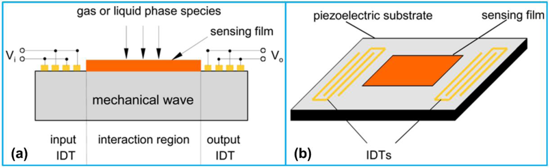
Schematic illustration of (a) structure and (b) IDT configuration for a SAW sensor. Reproduced with permission [188]. Copyright 2009, MDPI.
3.3.2. Chemical sensing
Over the past decade, sensing chemicals in gaseous phase has been reported by using SAW devices based on Rayleigh waves [138]. Due to its large surface area and unique electronic properties, graphene has been adopted for fabricating SAW based chemical sensors. Arsat et al. [189] developed a 102 MHz SAW device for detecting H2 and CO. The device was composed of 9 nm thick graphene-like nano-sheets deposited on the active area of 36° YX lithium tantalate (LiTaO3) SAW transducer and 38 electrode pairs (IDT fingers) in both input and output IDTs. Raj et al. [190] developed a ZnO-coated one port SAW resonator for the detection of DMMP (dimethyl methyl phosphonate), a simulant of the chemical warfare agent Sarin at room temperature. The device worked at a center frequency of 433 MHz. With DMMP exposure, the frequency shift of the device was increased with the thickness of ZnO film. Luo et al. [191] reported a SAW sensor composed of nanocrystalline SnO2 film for H2S detection. The sensing principle of the device was based on the acoustoelectric effect due to the electrical conductivity variation of the SnO2 film. The maximal response of the sensor (i.e., center frequency change) was 112.232 kHz when the sensor with a 275 nm thick SnO2 film was operated at 120 °C.
3.3.3. Biosensing
A biosensor typically consists of a biologically active component (antibody or enzyme) confined on the surface of a transducer, which enables the detection of target component in a complex mixture [192]. Conventionally, the most widely used acoustic devices for biosensing are operated at thickness shear mode [193] that are classified as bulk acoustic wave devices and are found in quartz crystal microbalances (QCMs). However, biosensing based on SAW has been reported to be more sensitive than the typical QCM-based biosensors. Since the first SAW biosensor was successfully developed in 1987 [194], SAW devices have been widely employed as biosensors to discover proteins, viruses, DNA, and cells [195].
Lee et al. [196] reported a 200 MHz SH-SAW device as immunosensor for detecting cardiac markers including cardiac troponin (cTn), creatine kinase (CK), and myoglobin (Mb), in human serum (Figure 11a). Antibody and gold nanoparticle conjugation was utilized as receptor, which was immobilized on the sensing area between two IDTs. They found that the propagation of SAWs was varied with the concentration of the conjugated antibodies. Baca et al. [197] developed a SAW biosensor for rapid detection of Ebola virus no need of sample processing and professional staff. Two different lanes consisting of antibodies were adopted on the surface of the biosensor: test lane with Ebola antibodies and reference lane with a control group (Figure 11b). The phase information of the SAWs was recorded and compared between these two lanes. It was found that there was a phase shift between these two lanes of antibodies. In addition, Cai et al. [198] utilized a 6.4 GHz SAW device working at third-order harmonic mode to detect DNA sequences. Due to the adopting of higher order mode, atomic sensing resolution could be achieved and single strands of DNA could be detected. It is well known that ZnO has excellent piezoelectric properties and relatively high electromechanical coupling coefficient, which can be potentially integrated with a SAW device [199]. Moreover, ZnO nanostructures demonstrate both piezoelectric and semiconducting properties [200], which makes them as promising candidates for various applications. It has been reported that ZnO thin film is deposited on a silicone substrate to electroacoustically generate hypersonic waves in SAW devices [201]. Augustine et al. [202] reported a SAW biosensor for potentially detecting cell proliferation in a cell culture system. The biosensor was made by electrospinning P(VDF-TrFE) fibers with ZnO nanoparticles over the sensing area (Figure 11c). The insertion loss of the developed biosensor encompassed with ZnO nanoparticles was much less than that of the only P(VDF-TrFE) deposited device.
Figure 11.

(a) Schematic of the sandwich immunoassay format utilized in combination with gold staining. Reproduced with permission [196]. Copyright 2011, American Chemical Society. (b) Principle of a SAW biosensor consisting of a test lane (red) and a reference lane (blue). Reproduced with permission [197]. Copyright 2015, MDPI. (c) Schematic of the SAW sensor composed of P(VDF-TrFE)/ZnO nanocomposites in the delay line area. Reproduced with permission [202]. Copyright 2016, Springer Nature.
3.3.4. Other nanoacoustic sensing
Besides SAW-based sensors, other types of acoustic sensors have also been reported. Gong et al. [203] developed a gold nanowire-based flexible pressure sensor which was fabricated by sandwiching gold nanowires between two thin PDMS sheets. The pressure sensor demonstrated low power consumption, high sensitivity, high stability, and fast response. The outstanding sensing properties along with the mechanical flexibility allowed the sensor to monitor heart rate (pulse) in real-time and detect tiny vibration forces from sound. Lang et al. [204] developed an acoustic sensor using PVDF nanofibers as a model polymer, which showed much higher sensitivity than the existing PVDF sensors. The developed sensor was especially sensitive to the sound waves in the low and middle frequency range, which made it appropriate for loud noise monitoring. Recently, Peng et al. [49] reported an ultrasonic sensor composed of a flexible piezo-composite structure and silver nanowire-based stretchable electrodes for noninvasive and continuous blood pressure monitoring (Figure 12a).
Figure 12.

(a) Flexible ultrasonic sensor for blood pressure monitoring. Reproduced with permission [49]. Copyright 2021, IEEE. (b) Laser-generated ultrasound-based stress sensing. Reproduced with permission [205]. Copyright 2020, IEEE.
Compared with the measurement results using a commercial blood pressure monitor, the ultrasonic sensor demonstrated the capability to measure the blood pressure waveform accurately on a human’s ulnar artery. Kim et al. [205] developed a stress sensing system consisting of a CSNP-PDMS composite-based laser ultrasound transmitter and an AlN piezoelectric receiver, placed in a semi-noncontact manner (Figure 12b). Subsurface longitudinal wave was generated by the transmitter and propagated parallel to the structural surface. The wave velocity would decrease linearly with the increase of the structural stress level according to the acoustoelastic effect.
More recently, for the first time, Shnaiderman et al. [206] developed a non-piezoelectric ultrasonic nanosensor (area 220 nm × 500 nm) with a dimension smaller than a blood cell for ultrasonic waves detection. Contrary to the commonly used piezoelectric sensors that the sensitivity is decreased with the reduction of the size, the submicrometer silicon waveguide–etalon detector (SWED) based on electro-optical technique can be miniaturized without sacrificing sensitivity. The SWED monitored the ultrasound-induced changes in light intensity propagating through the miniaturized photonic circuits, demonstrating an ultrabroad bandwidth of 230 MHz and a sensitivity orders of magnitude higher than that of piezoelectric sensors.
4. Conclusions and outlook
The field of nanoacoustics has been advancing remarkably over the past decade and continues to substantially expand its capabilities and refine its techniques. In this two-part review, for the first time, the recent progress in nanoacoustics was comprehensively presented. As part I of this two-part review, the recent advancement made in exploring nanomaterials and nanostructures for acoustics were reviewed including factors related to acoustic performance. Three different types of applications of nanoacoustics were summarized including material property characterization, nanomaterial/structure manipulation, and sensing, with special attention being paid to nanomaterials, nanostructures and nanodevice implementations. Despite the rapid progress and significant research achievements related to nanoacoustics, there are still many unsolved issues to be explored.
Compared with CB, CNTs, and CNFs, CSNPs produced higher photoacoustic conversion efficiencies due to their high surface area to volume ratio. While the CSNP approach has merits in terms of nanostructure, fabrication, and photoacoustic performance, there is still much to be explored about the performance limits including the maximum pressure output by high fluence excitation and the maximum peak negative pressure.
While acoustic nanomanipulation has demonstrated great potential for various applications including biomedicine and micro/nanofabrication, many issues remain to be explored in our understanding of the underlying principles of forming SAW inside microchannels. In addition, further investigations are necessary to expand our understanding of different phenomenon. The future development of acoustic nanomanipulation devices for practical application includes integrating devices for high precision and controllability.
Due to the inherent advantages of SAW-based sensing platforms, it is anticipated that the functionalization of SAW devices for increased selectivity will remain to be an active research area in the near future. Investigations focus on SAW-based sensing should continue exploration of novel sensing materials to advance performance levels and to broaden the applications. Moreover, one of the limitations of the current SAW-based sensors is that they require expensive electronic detection systems, such as network analyzers, to successfully record device behaviors. In the future, small, portable devices for data acquisition are needed that can be packaged into a highly integrated and cost-effective systems.
Acknowledgments
The authors would like to acknowledge the financial support from the National Institutes of Health under the grants R01HL141967, R41HL154735, and R21EB027304; Office of Naval Research under the grant N00014-18-1-2538; and Department of Energy under the grant DE-NE0008708.
Footnotes
Declaration of competing interest
Xiaoning Jiang has a financial interest in SonoVascular, Inc., who licensed an intravascular sonothrombolysis technology from North Carolina State University.
References
- [1].Ng K, Liu Y, Therapeutic ultrasound: its application in drug delivery, Med. Res. Rev 22 (2002) 204–223. [DOI] [PubMed] [Google Scholar]
- [2].Asher RC, Ultrasonic Sensors Bristol and Philadelphia, (1997). [Google Scholar]
- [3].Ciaravino V, Biological Effects of Ultrasound: Mechanisms and Clinical Implications (NCRP Report No. 74), Med. Phys 13 (1986) 424. [Google Scholar]
- [4].Fellinger K, Schmid J, Klinik und Therapie des chronischen Gelenkrheumatismus, Verlag für Medizinische Wissenschaften, 1954. [Google Scholar]
- [5].Rumack CM, Levine D, Diagnostic ultrasound E-book, Elsevier Health Sciences, 2017. [Google Scholar]
- [6].Peng C, Kim H-W, Kim T, Jiang X, Blood volume flow measurement using a flexible ultrasound transducer (Conference Presentation), in: Heal. Monit. Struct. Biol. Syst. XIII, International Society for Optics and Photonics, 2019: p. 1097227. [Google Scholar]
- [7].Peng C, Chen M, Sim HK, Zhu Y, Jiang X, Blood pressure measurement using a flexible piezo-composite ultrasonic transducer (Conference Presentation), in: Heal. Monit. Struct. Biol. Syst. IX, International Society for Optics and Photonics, 2020: p. 1138111. [Google Scholar]
- [8].Peng C, Chen M, Sim HK, Zhu Y, Jiang X, A Flexible Piezo-Composite Ultrasound Blood Pressure Sensor with Silver Nanowire-based Stretchable Electrodes, in: 2020 IEEE 15th Int. Conf. Nano/Micro Eng. Mol. Syst., IEEE, 2020: pp. 143–146. [Google Scholar]
- [9].Zhuang Y, Li J, Hu Q, Han S, Liu W, Peng C, Li Z, Zhang L, Wei X, Xu Z, Flexible composites with Ce-doped BaTiO3/P (VDF-TrFE) nanofibers for piezoelectric device, Compos. Sci. Technol 200 (2020) 108386. [Google Scholar]
- [10].Paliwal S, Mitragotri S, Ultrasound-induced cavitation: applications in drug and gene delivery, Expert Opin. Drug Deliv 3 (2006) 713–726. [DOI] [PubMed] [Google Scholar]
- [11].Barnett SB, Ter Haar GR, Ziskin MC, Rott H-D, Duck FA, Maeda K, International recommendations and guidelines for the safe use of diagnostic ultrasound in medicine, Ultrasound Med. Biol 26 (2000) 355–366. [DOI] [PubMed] [Google Scholar]
- [12].Miller DL, Smith NB, Bailey MR, Czarnota GJ, Hynynen K, Makin IRS, B.C. of the A.I. of U. in Medicine, Overview of therapeutic ultrasound applications and safety considerations, J. Ultrasound Med 31 (2012) 623–634. [DOI] [PMC free article] [PubMed] [Google Scholar]
- [13].Wang X, Gkanatsas Y, Palasubramaniam J, Hohmann JD, Chen YC, Lim B, Hagemeyer CE, Peter K, Thrombus-targeted theranostic microbubbles: a new technology towards concurrent rapid ultrasound diagnosis and bleeding-free fibrinolytic treatment of thrombosis, Theranostics 6 (2016) 726. [DOI] [PMC free article] [PubMed] [Google Scholar]
- [14].Wood AKW, Sehgal CM, A review of low-intensity ultrasound for cancer therapy, Ultrasound Med. Biol 41 (2015) 905–928. [DOI] [PMC free article] [PubMed] [Google Scholar]
- [15].Humphrey VF, Ultrasound and matter—Physical interactions, Prog. Biophys. Mol. Biol 93 (2007) 195–211. [DOI] [PubMed] [Google Scholar]
- [16].Peng C, Ravi S, Patel VK, Momen AM, Moghaddam S, Physics of direct-contact ultrasonic cloth drying process, Energy 125 (2017). doi: 10.1016/j.energy.2017.02.138. [DOI] [Google Scholar]
- [17].Peng C, Momen AM, Moghaddam S, An energy-efficient method for direct-contact ultrasonic cloth drying, Energy 138 (2017). doi: 10.1016/j.energy.2017.07.025. [DOI] [Google Scholar]
- [18].Peng C, Lai H, Orazem ME, Moghaddam S, Microstructure of clay fabric in electrokinetic dewatering of phosphatic clay dispersions, Appl. Clay Sci 158 (2018). doi: 10.1016/j.clay.2018.03.020. [DOI] [Google Scholar]
- [19].Peng C, Moghaddam S, The Study of Fabric Drying Using Direct-Contact Ultrasonic Vibration, IntechOpen, 2019. doi: 10.5772/intechopen.89424. [DOI] [Google Scholar]
- [20].Peng C, Comment on the paper “Generation and reduction of bulk nanobubbles by ultrasonic irradiation” by Keiji Yasuda, Hodaka Matsushima, and Yoshiyuki Asakura, Chemical Engineering Science 195 (2019) 455–461, Chem. Eng. Sci 207 (2019) 1364–1365. [Google Scholar]
- [21].Peng C, Moghaddam S, Energy efficient piezoelectrically actuated transducer for direct-contact ultrasonic drying of fabrics, Dry. Technol 38 (2020) 879–888. [Google Scholar]
- [22].Peng C, Moghaddam S, Experimental Evaluation and Kinetic Analysis of Direct-Contact Ultrasonic Fabric Drying Process, J. Therm. Sci. Eng. Appl 13 (2021). [Google Scholar]
- [23].Banerjee HN, Verma M, Application of nanotechnology in cancer, Technol. Cancer Res. Treat 7 (2008) 149–154. [DOI] [PubMed] [Google Scholar]
- [24].Cuenca AG, Jiang H, Hochwald SN, Delano M, Cance WG, Grobmyer SR, Emerging implications of nanotechnology on cancer diagnostics and therapeutics, Cancer 107 (2006) 459–466. [DOI] [PubMed] [Google Scholar]
- [25].Farokhzad OC, Langer R, Nanomedicine: developing smarter therapeutic and diagnostic modalities, Adv. Drug Deliv. Rev 58 (2006) 1456–1459. [DOI] [PubMed] [Google Scholar]
- [26].Nie S, Xing Y, Kim GJ, Simons JW, Nanotechnology applications in cancer, Annu. Rev. Biomed. Eng 9 (2007) 257–288. [DOI] [PubMed] [Google Scholar]
- [27].Wang X, Yang L, Chen Z, Shin DM, Application of nanotechnology in cancer therapy and imaging, CA. Cancer J. Clin 58 (2008) 97–110. [DOI] [PubMed] [Google Scholar]
- [28].Barreto JA, O’Malley W, Kubeil M, Graham B, Stephan H, Spiccia L, Nanomaterials: applications in cancer imaging and therapy, Adv. Mater 23 (2011) H18–H40. [DOI] [PubMed] [Google Scholar]
- [29].Geng J, Li W, Smaga LP, Sottos NR, Chan J, Damage-Responsive Microcapsules for Amplified Photoacoustic Detection of Microcracks in Polymers, Chem. Mater 30 (2018) 2198–2202. [Google Scholar]
- [30].Shekhawat GS, Srivastava AK, Dravid VP, Balogun O, Thickness Resonance Acoustic Microscopy for Nanomechanical Subsurface Imaging, ACS Nano 11 (2017) 6139–6145. doi: 10.1021/acsnano.7b02170. [DOI] [PubMed] [Google Scholar]
- [31].Ding X, Peng Z, Lin S-CS, Geri M, Li S, Li P, Chen Y, Dao M, Suresh S, Huang TJ, Cell separation using tilted-angle standing surface acoustic waves, Proc. Natl. Acad. Sci 111 (2014) 12992–12997. [DOI] [PMC free article] [PubMed] [Google Scholar]
- [32].Diauudin FN, Rashid JIA, Knight VF, Yunus WMZW, Ong KK, Kasim NAM, Halim NA, Noor SAM, A review of current advances in the detection of organophosphorus chemical warfare agents based biosensor approaches, Sens. Bio-Sensing Res 26 (2019) 100305. [Google Scholar]
- [33].Siwawannapong K, Zhang R, Lei H, Jin Q, Tang W, Dong Z, Lai R-Y, Liu Z, Kamkaew A, Cheng L, Ultra-small pyropheophorbide-a nanodots for near-infrared fluorescence/photoacoustic imaging-guided photodynamic therapy, Theranostics 10 (2020) 62. [DOI] [PMC free article] [PubMed] [Google Scholar]
- [34].Guo B, Chen J, Chen N, Middha E, Xu S, Pan Y, Wu M, Li K, Liu C, Liu B, High-Resolution 3D NIR-II Photoacoustic Imaging of Cerebral and Tumor Vasculatures Using Conjugated Polymer Nanoparticles as Contrast Agent, Adv. Mater 31 (2019) 1808355. [DOI] [PubMed] [Google Scholar]
- [35].Chiang C-F, Hsu Y-H, Liu C-C, Liang P-C, Miaw S-C, Lin W-L, Pulsed-wave ultrasound hyperthermia enhanced nanodrug delivery combined with chloroquine exerts effective antitumor response and postpones recurrence, Sci. Rep 9 (2019) 1–10. [DOI] [PMC free article] [PubMed] [Google Scholar]
- [36].Wu X, Suo Y, Shi H, Liu R, Wu F, Wang T, Ma L, Liu H, Cheng Z, Deep-tissue Photothermal Therapy Using Laser Illumination at NIR-IIa Window, Nano-Micro Lett 12 (2020) 38. [DOI] [PMC free article] [PubMed] [Google Scholar]
- [37].Chen X, Li J, Zhang G, Shi Y, PZT nanoactive fiber composites for acoustic emission detection, Adv. Mater 23 (2011) 3965–3969. [DOI] [PubMed] [Google Scholar]
- [38].Sun B, Li X, Zhao R, Ji H, Qiu J, Zhang N, He D, Wang C, Electrospun poly (vinylidene fluoride)-zinc oxide hierarchical composite fiber membrane as piezoelectric acoustoelectric nanogenerator, J. Mater. Sci 54 (2019) 2754–2762. [Google Scholar]
- [39].Chen X, Guo S, Li J, Zhang G, Lu M, Shi Y, Flexible piezoelectric nanofiber composite membranes as high performance acoustic emission sensors, Sensors Actuators A Phys 199 (2013) 372–378. [Google Scholar]
- [40].Lang C, Fang J, Shao H, Ding X, Lin T, High-sensitivity acoustic sensors from nanofibre webs, Nat. Commun 7 (2016) 1–7. doi: 10.1038/ncomms11108. [DOI] [PMC free article] [PubMed] [Google Scholar]
- [41].Shi Y, Piezoelectric Nanofibers and Their Applications in Energy Harvesting, (2019).
- [42].Shrout TR, Chang ZP, Kim N, Markgraf S, Dielectric behavior of single crystals near the (1− X) Pb (Mg1/3Nb2/3) O3-(x) PbTiO3 morphotropic phase boundary, Ferroelectr. Lett. Sect 12 (1990) 63–69. [Google Scholar]
- [43].Zhao X, Fang B, Cao H, Guo Y, Luo H, Dielectric and piezoelectric performance of PMN–PT single crystals with compositions around the MPB: influence of composition, poling field and crystal orientation, Mater. Sci. Eng. B 96 (2002) 254–262. [Google Scholar]
- [44].Zhang S, Li F, High performance ferroelectric relaxor-PbTiO3 single crystals: Status and perspective, J. Appl. Phys 111 (2012) 2. [Google Scholar]
- [45].Chang W-Y, Huang W, Bagal A, Chang C-H, Tian J, Han P, Jiang X, Study on dielectric and piezoelectric properties of 0.7 Pb (Mg1/3Nb2/3) O3–0.3 PbTiO3 single crystal with nano-patterned composite electrode, J. Appl. Phys 114 (2013) 114103. [DOI] [PMC free article] [PubMed] [Google Scholar]
- [46].Chang W-Y, Chung C-C, Yuan Z, Chang C-H, Tian J, Viehland D, Li J-F, Jones JL, Jiang X, Patterned nano-domains in PMN-PT single crystals, Acta Mater 143 (2018) 166–173. [Google Scholar]
- [47].Gao M, Luo C, Chang W-Y, Leung CM, Tian J, Li J, Jiang X, Viehland D, Apparent phase stability and domain distribution of PMN-30PT single crystals with nanograted Au/MnOx electrodes, Acta Mater 169 (2019) 28–35. [Google Scholar]
- [48].Luo C, Chang W-Y, Gao M, Chang C-H, Li J, Viehland D, Tian J, Jiang X, Multi-layered domain morphology in relaxor single crystals with nano-patterned composite electrode, Acta Mater 182 (2020) 10–17. [Google Scholar]
- [49].Peng C, Chen M, Sim HK, Zhu Y, Jiang X, Noninvasive and Nonocclusive Blood Pressure Monitoring via a Flexible Piezo-Composite Ultrasonic Sensor, IEEE Sens. J 21 (2020) 2642–2650. [Google Scholar]
- [50].Jiang X, Kim T, Zhu Y, Flexible Piezo-Composite Sensors and Transducers, (2020).
- [51].Kim T, Cui Z, Chang W-Y, Kim H-W, Zhu Y, Jiang X, Flexible 1–3 Composite Ultrasound Transducers with Silver Nanowire-based Stretchable Electrodes, IEEE Trans. Ind. Electron (2019). [Google Scholar]
- [52].Li C, Wang LV, Photoacoustic tomography and sensing in biomedicine, Phys. Med. Biol 54 (2010) 1–52. doi: 10.1088/0031-9155/54/19/R01.Photoacoustic. [DOI] [PMC free article] [PubMed] [Google Scholar]
- [53].Hutchins DA, Mechanisms of pulsed photoacoustic generation, Can. J. Phys 64 (1986) 1247–1264. [Google Scholar]
- [54].Tam AC, Applications of photoacoustic sensing techniques, Rev. Mod. Phys 58 (1986) 381. [Google Scholar]
- [55].White RM, Generation of Elastic Waves by Transient Elastic Heating, J. Appl. Phys 34 (1963) 3559–3567. doi: 10.1063/1.1729258. [DOI] [Google Scholar]
- [56].Dewhurst RJ, Hutchins DA, Palmer SB, Scruby CB, Quantitative measurements of laser-generated acoustic waveforms, J. Appl. Phys 53 (1982) 4064–4071. [Google Scholar]
- [57].Korpel A, Adler R, Alpiner B, Direct Observation of Optically Induced Generation and Amplication of Sound, Appl. Phys. Lett 5 (1964) 86–88. [Google Scholar]
- [58].Carr PH, Harmonic generation of microwave phonons by radiation pressure and by the phonon phonon interaction, IEEE Trans. Sonics Ultrason 13 (1966) 103–108. [Google Scholar]
- [59].Deán-Ben XL, Gottschalk S, Mc Larney B, Shoham S, Razansky D, Advanced optoacoustic methods for multiscale imaging of in vivo dynamics, Chem. Soc. Rev 46 (2017) 2158–2198. [DOI] [PMC free article] [PubMed] [Google Scholar]
- [60].Kim J, Kim H, Chang W-Y, Huang W, Jiang X, Dayton PA, Candle-Soot Carbon Nanoparticles in Photoacoustics: Advantages and Challenges for Laser Ultrasound Transmitters, IEEE Nanotechnol. Mag 13 (2019) 13–28. [DOI] [PMC free article] [PubMed] [Google Scholar]
- [61].Wetsel GC, Photothermal generation of thermoelastic waves in composite media, IEEE Trans. Ultrason. Ferroelectr. Freq. Control 33 (1986) 450–461. [DOI] [PubMed] [Google Scholar]
- [62].McDonald FA, Practical quantitative theory of photoacoustic pulse generation, Appl. Phys. Lett 54 (1989) 1504–1506. [Google Scholar]
- [63].Chang W, Huang W, Kim J, Li S, Jiang X, Candle soot nanoparticles-polydimethylsiloxane composites for laser ultrasound transducers, Appl. Phys. Lett 107 (2015) 161903. [Google Scholar]
- [64].Hou Y, Kim JS, Ashkenazi S, O’Donnell M, Guo LJ, Optical generation of high frequency ultrasound using a two dimensional array of gold nanoparticles, Proc. - IEEE Ultrason. Symp 1 (2006) 401–404. doi: 10.1109/ULTSYM.2006.113. [DOI] [Google Scholar]
- [65].Buma T, Spisar M, Donnell MO, A High-Frequency, 2-D Array Element Using Thermoelastic Expansion in PDMS, IEEE Trans. Ultrason. Ferroelectr. Freq. Control 50 (2003) 1161–1176. doi: 10.1109/TUFFC.2003.1235327. [DOI] [PubMed] [Google Scholar]
- [66].V Wang L, Tutorial on photoacoustic microscopy and computed tomography, IEEE J. Sel. Top. Quantum Electron 14 (2008) 171–179. [Google Scholar]
- [67].Von Gutfeld RJ, Budd HF, Laser-generated MHz elastic waves from metallic-liquid interfaces, Appl. Phys. Lett 34 (1979) 617–619. [Google Scholar]
- [68].Buma T, Spisar M, O’donnell M, High-frequency ultrasound array element using thermoelastic expansion in an elastomeric film, Appl. Phys. Lett 79 (2001) 548–550. [Google Scholar]
- [69].Hsieh BY, Kim J, Zhu J, Li S, Zhang X, Jiang X, A laser ultrasound transducer using carbon nanofibers-polydimethylsiloxane composite thin film, Appl. Phys. Lett 106 (2015) 1–5. doi: 10.1063/1.4905659. [DOI] [Google Scholar]
- [70].Hou Y, Kim J-S, Ashkenazi S, O’Donnell M, Guo LJ, Optical generation of high frequency ultrasound using two-dimensional gold nanostructure, Appl. Phys. Lett 89 (2006) 93901. [Google Scholar]
- [71].Wu N, Tian Y, Zou X, Silva V, Chery A, Wang X, High-efficiency optical ultrasound generation using one-pot synthesized polydimethylsiloxane-gold nanoparticle nanocomposite, JOSA B 29 (2012) 2016–2020. [Google Scholar]
- [72].Hwan Lee S, Park M, Yoh JJ, Song H, Yun Jang E, Hyup Kim Y, Kang S, Seop Yoon Y, Reduced graphene oxide coated thin aluminum film as an optoacoustic transmitter for high pressure and high frequency ultrasound generation, Appl. Phys. Lett 101 (2012) 241909. [Google Scholar]
- [73].Karabutov AA, Kaptilniy AG, Ivochkin AY, Ksenofontov DM, Trofimov AD, Optoacoustic study of laser-induced near-critical states of thin aluminum films, Moscow Univ. Phys. Bull 68 (2013) 383–386. [Google Scholar]
- [74].Yoo G, Park Y, Sang P, Baac HW, Heo J, High-frequency optoacoustic transmitter based on nanostructured germanium via metal-assisted chemical etching, Opt. Mater. Express 6 (2016) 2567–2572. [Google Scholar]
- [75].Hou Y, Ashkenazi S, Huang S, O’Donnell M, Improvements in optical generation of high-frequency ultrasound, IEEE Trans. Ultrason. Ferroelectr. Freq. Control 54 (2007) 682–686. [DOI] [PubMed] [Google Scholar]
- [76].Huang W, Chang W-Y, Kim J, Li S, Huang S, Jiang X, A novel laser ultrasound transducer using candle soot carbon nanoparticles, IEEE Trans. Nanotechnol 15 (2016) 395–401. [Google Scholar]
- [77].Chang W-Y, Zhang XA, Kim J, Huang W, Bagal A, Chang C-H, Fang T, Wu HF, Jiang X, Evaluation of photoacoustic transduction efficiency of candle soot nanocomposite transmitters, IEEE Trans. Nanotechnol 17 (2018) 985–993. [Google Scholar]
- [78].Kim T, Chang W-Y, Kim H, Jiang X, Narrow band photoacoustic lamb wave generation for nondestructive testing using candle soot nanoparticle patches, Appl. Phys. Lett 115 (2019) 102902. [Google Scholar]
- [79].Colchester RJ, Mosse CA, Bhachu DS, Bear JC, Carmalt CJ, Parkin IP, Treeby BE, Papakonstantinou I, Desjardins AE, Laser-generated ultrasound with optical fibres using functionalised carbon nanotube composite coatings, Appl. Phys. Lett 104 (2014) 173502. [Google Scholar]
- [80].Hsieh B-Y, Kim J, Zhu J, Li S, Zhang X, Jiang X, A laser ultrasound transducer using carbon nanofibers–polydimethylsiloxane composite thin film, Appl. Phys. Lett 106 (2015) 21902. [Google Scholar]
- [81].Di J, Kim J, Hu Q, Jiang X, Gu Z, Spatiotemporal drug delivery using laser-generated-focused ultrasound system, J. Control. Release 220 (2015) 592–599. doi: 10.1016/j.jconrel.2015.08.033. [DOI] [PMC free article] [PubMed] [Google Scholar]
- [82].Alles EJ, Noimark S, Zhang E, Beard PC, Desjardins AE, Pencil beam all-optical ultrasound imaging, Biomed. Opt. Express 7 (2016) 3696–3704. [DOI] [PMC free article] [PubMed] [Google Scholar]
- [83].Baac HW, Ok JG, Maxwell A, Lee K-T, Chen Y-C, Hart AJ, Xu Z, Yoon E, Guo LJ, Carbon-nanotube optoacoustic lens for focused ultrasound generation and high-precision targeted therapy, Sci. Rep 2 (2012) 989. [DOI] [PMC free article] [PubMed] [Google Scholar]
- [84].Baac HW, Lee T, Guo LJ, Micro-ultrasonic cleaving of cell clusters by laser-generated focused ultrasound and its mechanisms, Biomed. Opt. Express 4 (2013) 1442–1450. [DOI] [PMC free article] [PubMed] [Google Scholar]
- [85].Baac HW, Lee T, Ok JG, Hall T, Jay Guo L, Dual-frequency focused ultrasound using optoacoustic and piezoelectric transmitters for single-pulsed free-field cavitation in water, Appl. Phys. Lett 103 (2013) 234103. [Google Scholar]
- [86].Lee T, Luo W, Li Q, Demirci H, Guo LJ, Laser-Induced Focused Ultrasound for Cavitation Treatment: Toward High-Precision Invisible Sonic Scalpel, Small 13 (2017) 1701555. [DOI] [PubMed] [Google Scholar]
- [87].Lee T, Ok JG, Guo LJ, Baac HW, Low f-number photoacoustic lens for tight ultrasonic focusing and free-field micro-cavitation in water, Appl. Phys. Lett 108 (2016) 104102. [Google Scholar]
- [88].Noimark S, Colchester RJ, Blackburn BJ, Zhang EZ, Alles EJ, Ourselin S, Beard PC, Papakonstantinou I, Parkin IP, Desjardins AE, Carbon‐nanotube–PDMS composite coatings on optical fibers for all‐optical ultrasound imaging, Adv. Funct. Mater 26 (2016) 8390–8396. [Google Scholar]
- [89].Poduval RK, Noimark S, Colchester RJ, Macdonald TJ, Parkin IP, Desjardins AE, Papakonstantinou I, Optical fiber ultrasound transmitter with electrospun carbon nanotube-polymer composite, Appl. Phys. Lett 110 (2017) 223701. [DOI] [PMC free article] [PubMed] [Google Scholar]
- [90].Chang W, Zhang XA, Kim J, Huang W, Bagal A, Chang C, Fang T, Wu HF, Jiang X, Evaluation of Photoacoustic Transduction Efficiency of Candle Soot Nanocomposite Transmitters, IEEE Trans. Nanotechnol 17 (2018) 985–993. doi: 10.1109/TNANO.2018.2845703. [DOI] [Google Scholar]
- [91].Li Y, Guo Z, Li G, Chen S-L, Miniature fiber-optic high-intensity focused ultrasound device using a candle soot nanoparticles-polydimethylsiloxane composites-coated photoacoustic lens, Opt. Express 26 (2018) 21700–21711. [DOI] [PubMed] [Google Scholar]
- [92].Wickramasinghe HK, Scanning acoustic microscopy: a review, J. Microsc 129 (1983) 63–73. doi: 10.1016/0041-624X(93)90070-G. [DOI] [Google Scholar]
- [93].Yu Z, Boseck S, Scanning acoustic microscopy and its applications to material characterization, Rev. Mod. Phys 67 (1995) 863. [Google Scholar]
- [94].Balogun O, Cole GD, Huber R, Chinn D, Murray TW, Spicer JB, High-spatial-resolution sub-surface imaging using a laser-based acoustic microscopy technique, IEEE Trans. Ultrason. Ferroelectr. Freq. Control 58 (2011) 226–233. doi: 10.1109/TUFFC.2011.1789. [DOI] [PubMed] [Google Scholar]
- [95].Briggs A, Advances in acoustic microscopy, Springer Science & Business Media, 2013. [Google Scholar]
- [96].Bertocci F, Grandoni A, Djuric-Rissner T, Scanning Acoustic Microscopy (SAM): A Robust Method for Defect Detection during the Manufacturing Process of Ultrasound Probes for Medical Imaging, Sensors 19 (2019) 4868. [DOI] [PMC free article] [PubMed] [Google Scholar]
- [97].Shan Y, Wang H, The structure and function of cell membranes examined by atomic force microscopy and single-molecule force spectroscopy, Chem. Soc. Rev 44 (2015) 3617–3638. [DOI] [PubMed] [Google Scholar]
- [98].da Fonseca RJ, Ferdj‐Allah L, Despaux G, Boudour A, Robert L, Attal J, Scanning Acoustic Microscopy-Recent Applications in Materials Science, Adv. Mater 5 (1993) 508–519. [Google Scholar]
- [99].Ahn P, Zhang Z, Sun C, Balogun O, Ultrasonic near-field optical microscopy using a plasmonic nanofocusing probe, J. Appl. Phys 113 (2013) 1–8. doi: 10.1063/1.4810925. [DOI] [Google Scholar]
- [100].Kolosov O, Yamanaka K, Nonlinear detection of ultrasonic vibrations in an atomic force microscope, Jpn. J. Appl. Phys 32 (1993) L1095. [Google Scholar]
- [101].Yamanaka K, Ogiso H, Kolosov O, Ultrasonic force microscopy for nanometer resolution subsurface imaging, Appl. Phys. Lett 64 (1994) 178–180. [Google Scholar]
- [102].Kester E, Rabe U, Presmanes L, Tailhades P, Arnold W, Measurement of Young’s modulus of nanocrystalline ferrites with spinel structures by atomic force acoustic microscopy, J. Phys. Chem. Solids 61 (2000) 1275–1284. [Google Scholar]
- [103].Rabe U, Amelio S, Kopycinska M, Hirsekorn S, Kempf M, Göken M, Arnold W, Imaging and measurement of local mechanical material properties by atomic force acoustic microscopy, Surf. Interface Anal. An Int. J. Devoted to Dev. Appl. Tech. Anal. Surfaces, Interfaces Thin Film 33 (2002) 65–70. [Google Scholar]
- [104].Amelio S, V Goldade A, Rabe U, Scherer V, Bhushan B, Arnold W, Measurements of elastic properties of ultra-thin diamond-like carbon coatings using atomic force acoustic microscopy, Thin Solid Films 392 (2001) 75–84. [Google Scholar]
- [105].Prasad M, Kopycinska M, Rabe U, Arnold W, Measurement of Young’s modulus of clay minerals using atomic force acoustic microscopy, Geophys. Res. Lett 29 (2002) 13–1. doi: 10.1029/2001gl014054. [DOI] [Google Scholar]
- [106].Yamanaka K, Ogiso H, Kolosov O, Ultrasonic force microscopy for nanometer resolution subsurface imaging, Appl. Phys. Lett 64 (1994) 178–180. doi: 10.1063/1.111524. [DOI] [Google Scholar]
- [107].Daly BC, Holme NCR, Buma T, Branciard C, Norris TB, Tennant DM, Taylor JA, Bower JE, Pau S, Imaging nanostructures with coherent phonon pulses, Appl. Phys. Lett 84 (2004) 5180–5182. [Google Scholar]
- [108].Richardson CJK, Spicer JB, Characterization of heat-treated tungsten thin films using picosecond duration thermoelastic transients, Opt. Lasers Eng 40 (2003) 379–391. [Google Scholar]
- [109].Ramanathan S, Cahill DG, High-resolution picosecond acoustic microscopy for noninvasive characterization of buried interfaces, J. Mater. Res 21 (2006) 1204–1208. [Google Scholar]
- [110].Lin K-H, Yu C-T, Sun S-Z, Chen H-P, Pan C-C, Chyi J-I, Huang S-W, Li P-C, Sun C-K, Two-dimensional nanoultrasonic imaging by using acoustic nanowaves, Appl. Phys. Lett 89 (2006) 43106. [Google Scholar]
- [111].Ahn P, Balogun O, Elastic characterization of nanoporous gold foams using laser based ultrasonics, Ultrasonics 54 (2014) 795–800. doi: 10.1016/j.ultras.2013.10.004. [DOI] [PubMed] [Google Scholar]
- [112].Zeng FW, Spicer JB, Nano-acoustic resonators for sensing near-particle environments in polymer matrix nanocomposites, in: 2017 IEEE 17th Int. Conf. Nanotechnology, NANO; 2017, 2017: pp. 436–438. doi: 10.1109/NANO.2017.8117414. [DOI] [Google Scholar]
- [113].Hu J, Acoustic Micro/Nano Manipulations: An Editorial Review, Int. J. Radiol 1 (2014) 1–3. doi: 10.6051/j.issn.2313-3406.2014.01.3. [DOI] [Google Scholar]
- [114].Ashkin A, Acceleration and trapping of particles by radiation pressure, Phys. Rev. Lett 24 (1970) 156. [DOI] [PubMed] [Google Scholar]
- [115].Ashkin A, Optical trapping and manipulation of neutral particles using lasers: a reprint volume with commentaries, World Scientific, 2006. [DOI] [PMC free article] [PubMed] [Google Scholar]
- [116].Tanase M, Bauer LA, Hultgren A, Silevitch DM, Sun L, Reich DH, Searson PC, Meyer GJ, Magnetic alignment of fluorescent nanowires, Nano Lett 1 (2001) 155–158. [Google Scholar]
- [117].Lee S-W, Jeong M-C, Myoung J-M, Chae G-S, Chung I-J, Magnetic alignment of ZnO nanowires for optoelectronic device applications, Appl. Phys. Lett 90 (2007) 133115. [Google Scholar]
- [118].Castillo J, Dimaki M, Svendsen WE, Manipulation of biological samples using micro and nano techniques, Integr. Biol 1 (2008) 30–42. [DOI] [PubMed] [Google Scholar]
- [119].Mølhave K, Wich T, Kortschack A, Bøggild P, Pick-and-place nanomanipulation using microfabricated grippers, Nanotechnology 17 (2006) 2434. [DOI] [PubMed] [Google Scholar]
- [120].Sitters G, Kamsma D, Thalhammer G, Ritsch-Marte M, Peterman EJG, Wuite GJL, Acoustic force spectroscopy, Nat. Methods 12 (2015) 47–50. [DOI] [PubMed] [Google Scholar]
- [121].Pihl J, Sinclair J, Karlsson M, Orwar O, Microfluidics for cell-based assays, Mater. Today 8 (2005) 46–51. [Google Scholar]
- [122].Chen X, Lam KH, Chen R, Chen Z, Qian X, Zhang J, Yu P, Zhou Q, Acoustic levitation and manipulation by a high-frequency focused ring ultrasonic transducer, Appl. Phys. Lett 114 (2019) 54103. [Google Scholar]
- [123].Zhang J, Yang S, Chen C, Hartman JH, Huang P-H, Wang L, Tian Z, Zhang P, Faulkenberry D, Meyer JN, Surface acoustic waves enable rotational manipulation of Caenorhabditis elegans, Lab Chip 19 (2019) 984–992. [DOI] [PMC free article] [PubMed] [Google Scholar]
- [124].Ding X, Lin SS, Kiraly B, Yue H, Li S, Chiang I, Shi J, Benkovic SJ, Huang TJ, On-chip manipulation of single microparticles, cells, and organisms using surface acoustic waves, Proc. Natl. Acad. Sci 109 (2012) 11105–11109. doi: 10.1073/pnas.1209288109. [DOI] [PMC free article] [PubMed] [Google Scholar]
- [125].Qiu Y, Wang H, Demore CEM, Hughes DA, Glynne-Jones P, Gebhardt S, Bolhovitins A, Poltarjonoks R, Weijer K, Schönecker A, Hill M, Cochran S, Acoustic Devices for Particle and Cell Manipulation and Sensing, Sensors 14 (2014) 14806–14838. doi: 10.3390/s140814806. [DOI] [PMC free article] [PubMed] [Google Scholar]
- [126].Mao Z, Li P, Wu M, Bachman H, Mesyngier N, Guo X, Liu S, Costanzo F, Huang TJ, Enriching Nanoparticles via Acoustofluidics, ACS Nano 11 (2017) 603–612. doi: 10.1021/acsnano.6b06784. [DOI] [PMC free article] [PubMed] [Google Scholar]
- [127].Greenhall J, Guevara Vasquez F, Raeymaekers B, Continuous and unconstrained manipulation of micro-particles using phase-control of bulk acoustic waves, Appl. Phys. Lett 103 (2013) 74103. [Google Scholar]
- [128].Haslam MD, Raeymaekers B, Aligning carbon nanotubes using bulk acoustic waves to reinforce polymer composites, Compos. Part B Eng 60 (2014) 91–97. [Google Scholar]
- [129].Greenhall J, Guevara Vasquez F, Raeymaekers B, Dynamic behavior of microscale particles controlled by standing bulk acoustic waves, Appl. Phys. Lett 105 (2014) 144105. [Google Scholar]
- [130].Chaki S, Harizi W, Bourse G, Ourak M, Multi-technique approach for non destructive diagnostic of structural composite materials using bulk ultrasonic waves, guided waves, acoustic emission and infrared thermography, Compos. Part A Appl. Sci. Manuf 78 (2015) 358–361. [Google Scholar]
- [131].Gautam GP, Manipulation of Particles and Fluid Using Bulk Acoustic Waves in Microfluidics, (2019).
- [132].Hou Z, Zhou Z, Liu P, Pei Y, Deformable oscillation of particles patterning by parametric bulk acoustic waves, Extrem. Mech. Lett (2020) 100716. [Google Scholar]
- [133].Shi J, Mao X, Ahmed D, Colletti A, Huang TJ, Focusing microparticles in a microfluidic channel with standing surface acoustic waves (SSAW), Lab Chip 8 (2008) 221–223. [DOI] [PubMed] [Google Scholar]
- [134].Wang Z, Zhe J, Recent advances in particle and droplet manipulation for lab-on-a-chip devices based on surface acoustic waves, Lab Chip 11 (2011) 1280–1285. doi: 10.1039/c0lc00527d. [DOI] [PubMed] [Google Scholar]
- [135].Ding X, Li P, Lin SS, Stratton ZS, Nama N, Guo F, Slotcavage D, Mao X, Shi J, Costanzo F, Huang TJ, Surface acoustic wave microfluidics, Lab Chip 13 (2013) 3626–3649. doi: 10.1039/c3lc50361e. [DOI] [PMC free article] [PubMed] [Google Scholar]
- [136].Gedge M, Hill M, Acoustofluidics 17: Theory and applications of surface acoustic wave devices for particle manipulation, Lab Chip 12 (2012) 2998–3007. doi: 10.1039/c2lc40565b. [DOI] [PubMed] [Google Scholar]
- [137].Nam J, Lim H, Shin S, Manipulation of microparticles using surface acoustic wave in microfluidic systems: a brief review, Korea-Australia Rheol. J 23 (2011) 255–267. doi: 10.1007/s13367-011-0031-5. [DOI] [Google Scholar]
- [138].Devkota J, Ohodnicki PR, Greve DW, SAW sensors for chemical vapors and gases, Sensors (Switzerland) 17 (2017) 13–15. doi: 10.3390/s17040801. [DOI] [PMC free article] [PubMed] [Google Scholar]
- [139].Connacher W, Zhang N, Huang A, Mei J, Zhang S, Gopesh T, Friend J, Micro/nano acoustofluidics: materials, phenomena, design, devices, and applications, Lab Chip 18 (2018) 1952–1996. doi: 10.1039/c8lc00112j. [DOI] [PubMed] [Google Scholar]
- [140].Fu YQ, Luo JK, Nguyen NT, Walton AJ, Flewitt AJ, Zu XT, Li Y, Mchale G, Matthews A, Iborra E, Du H, Milne WI, Advances in piezoelectric thin films for acoustic biosensors, acoustofluidics and lab-on-chip applications, Prog. Mater. Sci 89 (2017) 31–91. doi: 10.1016/j.pmatsci.2017.04.006. [DOI] [Google Scholar]
- [141].Thurston RN, Pierce AD, Papadakis EP, Reference for Modern Instrumentation, Techniques, and Technology: Ultrasonic Instruments and Devices I: Ultrasonic Instruments and Devices I, Academic Press, 1998. [Google Scholar]
- [142].Wohltjen H, Mechanism of operation and design considerations for surface acoustic wave device vapour sensors, Sensors and Actuators 5 (1984) 307–325. [Google Scholar]
- [143].Slobodnik AJ, Surface acoustic waves and SAW materials, Proc. IEEE 64 (1976) 581–595. [Google Scholar]
- [144].V Biryukov S, Schmidt H, Weihnacht M, Gyroscopic effect for SAW in common piezoelectric crystals, in: 2009 IEEE Int. Ultrason. Symp., IEEE, 2009: pp. 2133–2136. [Google Scholar]
- [145].Campbell CK, Applications of surface acoustic and shallow bulk acoustic wave devices, Proc. IEEE 77 (1989) 1453–1484. [Google Scholar]
- [146].Ben Salah I, Ben Ghozlen MH, Rayleigh waves in piezoelectric material, Phys. Procedia 2 (2009) 1377–1383. [Google Scholar]
- [147].Caliendo C, Analysis of the acoustoelectric behavior of microwave frequency, temperature-compensated AlN-based multilayer coupling configurations, J. Appl. Phys 104 (2008) 104509. [Google Scholar]
- [148].Ricco AJ, Martin SJ, Zipperian TE, Surface acoustic wave gas sensor based on film conductivity changes, Sensors and Actuators 8 (1985) 319–333. [Google Scholar]
- [149].Naumenko N, Solie L, Optimal cuts of langasite, La/sub 3/Ga/sub 5/SiO/sub 14/for SAW devices, Ieee Trans. Ultrason. Ferroelectr. Freq. Control 48 (2001) 530–537. [DOI] [PubMed] [Google Scholar]
- [150].Destgeer G, Sung HJ, Recent advances in microfluidic actuation and micro-object manipulation via surface acoustic waves, Lab Chip 15 (2015) 2722–2738. doi: 10.1039/C5LC00265F. [DOI] [PubMed] [Google Scholar]
- [151].Yeo LY, Friend JR, Surface Acoustic Wave Microfluidics, Annu. Rev. Fluid Mech 46 (2014) 379–406. doi: 10.1146/annurev-fluid-010313-141418. [DOI] [Google Scholar]
- [152].Laurell T, Lenshof A, Microscale Acoustofluidics, Royal Society of Chemistry, 2014. [Google Scholar]
- [153].Friend J, Yeo LY, Microscale acoustofluidics: Microfluidics driven via acoustics and ultrasonics, Rev. Mod. Phys 83 (2011) 647. doi: 10.1103/RevModPhys.83.647. [DOI] [Google Scholar]
- [154].Lefebvre AH, McDonell VG, Atomization and sprays, CRC press, 2017. [Google Scholar]
- [155].Kurosawa M, Watanabe T, Futami A, Higuchi T, Surface acoustic wave atomizer, Sensors and Actuators-A-Physical Sensors 50 (1995) 69–74. [Google Scholar]
- [156].Alvarez M, Friend J, Yeo LY, Rapid generation of protein aerosols and nanoparticles via surface acoustic wave atomization, Nanotechnology 19 (2008) 455103. [DOI] [PubMed] [Google Scholar]
- [157].Friend JR, Yeo LY, Arifin DR, Mechler A, Evaporative self-assembly assisted synthesis of polymeric nanoparticles by surface acoustic wave atomization, Nanotechnology 19 (2008) 145301. [DOI] [PubMed] [Google Scholar]
- [158].Collins DJ, Ma Z, Han J, Ai Y, Continuous micro-vortex-based nanoparticle manipulation via focused surface acoustic waves, Lab Chip 17 (2017) 91–103. doi: 10.1039/c6lc01142j. [DOI] [PubMed] [Google Scholar]
- [159].Ren L, Zhou D, Mao Z, Xu P, Huang TJ, Mallouk TE, Rheotaxis of Bimetallic Micromotors Driven by Chemical–Acoustic Hybrid Power, ACS Nano 11 (2017) 10591–10598. doi: 10.1021/acsnano.7b06107. [DOI] [PubMed] [Google Scholar]
- [160].Baughman RH, Zakhidov AA, De Heer WA, Carbon nanotubes--the route toward applications, Science (80-. ) 297 (2002) 787–792. [DOI] [PubMed] [Google Scholar]
- [161].Strobl CJ, Schäflein C, Beierlein U, Ebbecke J, Wixforth A, Carbon nanotube alignment by surface acoustic waves, Appl. Phys. Lett 85 (2004) 1427–1429. [Google Scholar]
- [162].Smorodin T, Beierlein U, Ebbecke J, Wixforth A, Surface‐Acoustic‐Wave‐Enhanced Alignment of Thiolated Carbon Nanotubes on Gold Electrodes, Small 1 (2005) 1188–1190. [DOI] [PubMed] [Google Scholar]
- [163].Seemann KM, Ebbecke J, Wixforth A, Alignment of carbon nanotubes on pre-structured silicon by surface acoustic waves, Nanotechnology 17 (2006) 4529. [Google Scholar]
- [164].Shi J, Huang H, Stratton Z, Huang Y, Huang TJ, Continuous particle separation in a microfluidic channel via standing surface acoustic waves (SSAW), Lab Chip 9 (2009) 3354–3359. [DOI] [PubMed] [Google Scholar]
- [165].Shi J, Ahmed D, Mao X, Lin S-CS, Lawit A, Huang TJ, Acoustic tweezers: patterning cells and microparticles using standing surface acoustic waves (SSAW), Lab Chip 9 (2009) 2890–2895. [DOI] [PubMed] [Google Scholar]
- [166].Ozcelik A, Rufo J, Guo F, Gu Y, Li P, Lata J, Huang TJ, Acoustic tweezers for the life sciences, Nat. Methods 15 (2018) 1021–1028. [DOI] [PMC free article] [PubMed] [Google Scholar]
- [167].Meng L, Cai F, Li F, Zhou W, Niu L, Zheng H, Acoustic tweezers, J. Phys. D. Appl. Phys 52 (2019) 273001. [Google Scholar]
- [168].Baudoin M, Thomas J-L, Acoustic tweezers for particle and fluid micromanipulation, Annu. Rev. Fluid Mech 52 (2019). [Google Scholar]
- [169].Marzo A, Drinkwater BW, Holographic acoustic tweezers, Proc. Natl. Acad. Sci 116 (2019) 84–89. [DOI] [PMC free article] [PubMed] [Google Scholar]
- [170].Gor’kov LP, Forces acting on a small particle in an acoustic field within an ideal fluid, in: Dokl. Akad. Nauk, Russian Academy of Sciences, 1961: pp. 88–91. [Google Scholar]
- [171].Shi J, Zheng YB, Huang TJ, Surface Acoustic Wave-Driven Active Plasmonics based on Dynamic Patterning of Nanoparticles in Microfluidic Channels, in: IEEE 22nd Int. Conf. Micro Electro Mech. Syst., 2009: pp. 332–335. [Google Scholar]
- [172].Chen Y, Ding X, Lin SS, Yang S, Huang P, Nama N, Zhao Y, Nawaz AA, Guo F, Wang L, Huang TJ, Aligning Nanowires by Standing Surface Acoustic Waves, in: Int. MicroTAS 2012, 2012: pp. 1309–1311. [Google Scholar]
- [173].Wu M, Mao Z, Chen K, Bachman H, Chen Y, Rufo J, Ren L, Li P, Wang L, Huang TJ, Acoustic Separation of Nanoparticles in Continuous Flow, Adv. Funct. Mater 27 (2017) 1606039. doi: 10.1002/adfm.201606039. [DOI] [PMC free article] [PubMed] [Google Scholar]
- [174].Wu M, Ouyang Y, Wang Z, Zhang R, Huang P-H, Chen C, Li H, Li P, Quinn D, Dao M, Isolation of exosomes from whole blood by integrating acoustics and microfluidics, Proc. Natl. Acad. Sci 114 (2017) 10584–10589. [DOI] [PMC free article] [PubMed] [Google Scholar]
- [175].Wohltjen H, Dessy R, Surface acoustic wave probe for chemical analysis. I. Introduction and instrument description, Anal. Chem 51 (1979) 1458–1464. [Google Scholar]
- [176].Teles FRR, Fonseca LP, Trends in DNA biosensors, Talanta 77 (2008) 606–623. [Google Scholar]
- [177].Fu YQ, Luo JK, Nguyen NT, Walton AJ, Flewitt AJ, Zu XT, Li Y, McHale G, Matthews A, Iborra E, Du H, Milne WI, Advances in piezoelectric thin films for acoustic biosensors, acoustofluidics and lab-on-chip applications, Prog. Mater. Sci 89 (2017) 31–91. doi: 10.1016/j.pmatsci.2017.04.006. [DOI] [Google Scholar]
- [178].Khlebarov ZP, Stoyanova AI, Topalova DI, Surface acoustic wave gas sensors, Sensors Actuators B Chem 8 (1992) 33–40. [Google Scholar]
- [179].Bo L, Xiao C, Hualin C, Mohammad MA, Xiangguang T, Luqi T, Yi Y, Tianling R, Surface acoustic wave devices for sensor applications, J. Semicond 37 (2016) 21001. [Google Scholar]
- [180].Awang Z, Gas sensors: a review, Sens. Transducers 168 (2014) 61–75. [Google Scholar]
- [181].Caliendo C, Verardi P, Verona E, D’Amico A, Di Natale C, Saggio G, Serafini M, Paolesse R, Huq SE, Advances in SAW-based gas sensors, Smart Mater. Struct 6 (1997) 689. [Google Scholar]
- [182].Shiokawa S, Kondoh J, Surface acoustic wave sensors, Jpn. J. Appl. Phys 43 (2004) 2799–2802. [Google Scholar]
- [183].Jakubik WP, Surface acoustic wave-based gas sensors, Thin Solid Films 520 (2011) 986–993. [Google Scholar]
- [184].Priya RB, Venkatesan T, Pandiyarajan G, Pandya HM, A short review of saw sensors, J. Environ. Nanotechnol 4 (2015) 15–22. [Google Scholar]
- [185].Afzal A, Iqbal N, Mujahid A, Schirhagl R, Advanced vapor recognition materials for selective and fast responsive surface acoustic wave sensors: A review, Anal. Chim. Acta 787 (2013) 36–49. [DOI] [PubMed] [Google Scholar]
- [186].Cheeke JDN, Wang Z, Acoustic wave gas sensors, Sensors Actuators B Chem 59 (1999) 146–153. [Google Scholar]
- [187].Dorozhkin LM, Rozanov IA, Acoustic wave chemical sensors for gases, J. Anal. Chem 56 (2001) 399–416. [Google Scholar]
- [188].Rocha-Gaso MI, March-Iborra C, Montoya-Baides Á, Arnau-Vives A, Surface generated acoustic wave biosensors for the detection of pathogens: A review, Sensors 9 (2009) 5740–5769. doi: 10.3390/s9095740. [DOI] [PMC free article] [PubMed] [Google Scholar]
- [189].Arsat R, Breedon M, Shafiei M, Spizziri PG, Gilje S, Kaner RB, Kalantar-zadeh K, Wlodarski W, Graphene-like nano-sheets for surface acoustic wave gas sensor applications, Chem. Phys. Lett 467 (2009) 344–347. doi: 10.1016/j.cplett.2008.11.039. [DOI] [Google Scholar]
- [190].Bhasker Raj V, Tomar M, Nimal AT, Parmar Y, Sharma MU, Gupta V, ZnO surface acoustic wave sensor for the enhanced detection of DMMP, in: Solid State Phenom., Trans Tech Publ, 2012: pp. 69–72. [Google Scholar]
- [191].Luo W, Fu Q, Zhou D, Deng J, Liu H, Yan G, A surface acoustic wave H2S gas sensor employing nanocrystalline SnO2 thin film, Sensors Actuators B Chem 176 (2013) 746–752. [Google Scholar]
- [192].Montoya A, Ocampo A, March C, Fundamentals of piezoelectric immunosensors, in: Piezoelectric Transducers Appl, Springer, 2009: pp. 289–306. [Google Scholar]
- [193].Yatsuda H, Kogai T, 3F-3 Liquid sensor using SAW and SH-SAW on quartz, in: 2006 IEEE Ultrason. Symp., IEEE, 2006: pp. 552–555. [Google Scholar]
- [194].Flory CA, Baer RL, Surface transverse wave mode analysis and coupling to interdigital transducers, in: IEEE 1987 Ultrason. Symp., IEEE, 1987: pp. 313–318. [Google Scholar]
- [195].Grate JW, Frye GC, Acoustic wave sensors, Sensors Updat 2 (1996) 37–83. [Google Scholar]
- [196].Lee J, Choi Y-S, Lee Y, Lee HJ, Lee JN, Kim SK, Han KY, Cho EC, Park JC, Lee SS, Sensitive and simultaneous detection of cardiac markers in human serum using surface acoustic wave immunosensor, Anal. Chem 83 (2011) 8629–8635. [DOI] [PubMed] [Google Scholar]
- [197].Baca J, Severns V, Lovato D, Branch D, Larson R, Rapid detection of Ebola virus with a reagent-free, point-of-care biosensor, Sensors 15 (2015) 8605–8614. [DOI] [PMC free article] [PubMed] [Google Scholar]
- [198].Cai H-L, Yang Y, Chen X, Mohammad MA, Ye T-X, Guo C-R, Yi L-T, Zhou C-J, Liu J, Ren T-L, A third-order mode high frequency biosensor with atomic resolution, Biosens. Bioelectron 71 (2015) 261–268. [DOI] [PubMed] [Google Scholar]
- [199].Du XY, Fu YQ, Tan SC, Luo JK, Flewitt AJ, Maeng S, Kim SH, Choi YJ, Lee DS, Park NM, ZnO film for application in surface acoustic wave device, in: J. Phys. Conf. Ser, IOP Publishing, 2007: p. 12035. [Google Scholar]
- [200].Sirelkhatim A, Mahmud S, Seeni A, Kaus NHM, Ann LC, Bakhori SKM, Hasan H, Mohamad D, Review on zinc oxide nanoparticles: antibacterial activity and toxicity mechanism, Nano-Micro Lett 7 (2015) 219–242. [DOI] [PMC free article] [PubMed] [Google Scholar]
- [201].Le Brizoual L, Krueger JK, Elmazria O, Vincent B, Bouvot L, Kolle M, Rouxel D, Alnot P, Mapping of microwave-induced phonons by μ-Brillouin spectroscopy: hypersons in ZnO on silicon, J. Phys. D. Appl. Phys 41 (2008) 105502. [Google Scholar]
- [202].Augustine R, Sarry F, Kalarikkal N, Thomas S, Badie L, Rouxel D, Surface acoustic wave device with reduced insertion loss by electrospinning P (VDF–TrFE)/ZnO nanocomposites, Nano-Micro Lett 8 (2016) 282–290. [DOI] [PMC free article] [PubMed] [Google Scholar]
- [203].Gong S, Schwalb W, Wang Y, Chen Y, Tang Y, Si J, Shirinzadeh B, Cheng W, A wearable and highly sensitive pressure sensor with ultrathin gold nanowires, Nat. Commun 5 (2014) 3132. [DOI] [PubMed] [Google Scholar]
- [204].Lang C, Fang J, Shao H, Ding X, Lin T, High-sensitivity acoustic sensors from nanofibre webs, Nat. Commun 7 (2016) 11108. [DOI] [PMC free article] [PubMed] [Google Scholar]
- [205].Kim H, Chang W-Y, Kim T, Jiang X, Stress Sensing Method via Laser-Generated Ultrasound Wave Using Candle Soot Nanoparticle Composite, IEEE Trans. Ultrason. Ferroelectr. Freq. Control (2020). [DOI] [PubMed] [Google Scholar]
- [206].Shnaiderman R, Wissmeyer G, Ülgen O, Mustafa Q, Chmyrov A, Ntziachristos V, A submicrometre silicon-on-insulator resonator for ultrasound detection, Nature 585 (2020) 372–378. [DOI] [PubMed] [Google Scholar]