Abstract
Objective:
The aim of this study was to construct an anthropomorphic maxillofacial phantom for dental imaging and dosimetry purposes using three-dimensional (3D) printing technology and materials that simulate the radiographic properties of tissues.
Methods:
Stereolithography photoreactive resins, polyurethane rubber and epoxy resin were modified by adding calcium carbonate and strontium carbonate powders or glass bubbles. These additives were used to change the materials’ CT numbers to mimic various body tissues. A maxillofacial phantom was designed using CT images of a head.
Results:
Commercial 3D printing resins were found to have CT numbers near 120 HU and were used to print intervertebral discs and an external skin for the maxillofacial phantom. By adding various amounts of calcium carbonate and strontium carbonate powders the CT number of the resin was raised to 1000 & 1500 HU and used to print bone mimics. Epoxy resin modified by adding glass bubbles was used in assembly and as a cartilaginous mimic. Glass bubbles were added to polyurethane rubber to reduce the CT number to simulate soft tissue and filled spaces between the printed anatomy and external skin of the phantom.
Conclusion:
The maxillofacial phantom designed for dental imaging and dosimetry constructed using 3D printing, polyurethane rubbers and epoxy resins represented a patient anatomically and radiographically. The results of the designed phantom, materials and assembly process can be applied to generate different phantoms that better represent diverse patient types and accommodate different ion chambers.
Keywords: printing, three-dimensional; phantoms, imaging; radiation dosage; diagnostic imaging
Introduction
Cone-beam computed tomography (CBCT) has steadily increased its role in diagnosing a wide range of conditions and for planning oral and maxillofacial surgery.1,2 However, the dose produced by CT for oral and maxillofacial imaging can be significant and impacts how this equipment can be used.3,4 Dose is especially a concern when imaging younger patients such as for orthodontics.5 Consequently, it is important to verify image quality and X-ray dose. Phantoms have been developed to assess image quality metrics such as image uniformity and the modulation transfer function.6,7 For dosimetric measurements, the challenge is to accurately compare patient doses between different systems and between different types of scans. The simplest approach is to take dose measurements in air without the use of a phantom. If the scanner uses automatic exposure control (AEC) that adjusts the kV and mAs then the measurements of dose in-air will be highly inaccurate. Using a simple geometric phantom, e.g. a cylinder, may not properly mimic a patient, and thus result in non-representative dose measurements. Alternatively, using an anthropomorphic phantom would provide a much more representative measurement of dose that a patient would receive.
In general, anthropomorphic phantoms are inanimate patient substitutes representing the anatomical structures of the body and simulate the radiographic properties of the tissues.8 By design, these are complex and can be difficult to make. One approach is to make anthropomorphic phantoms using human skulls.9 However, human skulls are difficult to obtain and it is very difficult to make two identical phantoms. Instead, it is common to use commercially produced phantoms, e.g. the Rando phantom, to make dose measurements.10 These phantoms, however, are available in a limited range of sizes and often have considerable cost. As a consequence, only a single anthropomorphic phantom representing an average adult male is normally used in practice. Adult females, adolescents and children are not properly represented. Evaluating the effect of dental implants may require reluctantly modifying an expensive phantom. It is much easier to use a simplified model of a head such as those developed by Yamauchi-Kawaura et al and by Najafi et al.11,12 These only incorporate the gross features of the head and are relatively straightforward to make using conventional machine shop techniques. The big disadvantages are the need for a machine shop and a lack of fine detail that could be important in some applications. Ideally, a medical physicist would be able to make a phantom themselves and easily incorporate modifications such as changing the size, accommodating ion chambers or thermoluminescent dosimeters and including resolution and contrast targets. A much easier approach is to use three-dimensional (3D) printers that easily make very complex objects at low cost. For example, 3D printing is now used routinely to make complex models of a patient’s anatomy for a very wide range of presurgical planning and surgical training applications.13–15 Similarly, 3D printing also enables the medical physicist to produce complex phantoms that accurately model human anatomy.16
Although 3D printers can easily reproduce the geometry of a skull and other tissues, mimicking the radiographic properties is a problem. Specifically, the range of CT numbers required for a head phantom is wide as shown by the values given in Table 117. The most common materials used in 3D printing have densities near one g/cm3 and radiographic properties similar to water. As discussed by Tino et al16 and Ehler et al18 there are few commercially available high- and low-density 3D printing materials that simulate the radiological properties, e.g. CT number given in Hounsfield units (HU), of bone, fat and lung tissues. Minor differences in CT number between various soft tissues are often ignored and a number of previous studies used materials that did not fully represent the radiological properties of bone or ignored bone entirely.19–22 For example, a head model by Homolka et al19 and torso models by Gear et al20 and Craft and Howell21 used the same material to mimic soft tissue and bone. Kim et al22 used materials that mimicked trabecular bone but were not representative of compact bone. They printed a spine phantom using digital light processing (DLP) and Polyjet printer technologies.22 The resulting lumbar vertebrae had respective CT numbers of approximately 152 and 98 HU that agreed with the ranges they proposed for patients 50–69 years. These CT numbers are quite low when compared to compact bone that has a CT number of roughly 1500 HU. Hazelaar et al23 obtained a much higher average CT number of 731 when mimicking a ribcage using gypsum material in a binder jet printer. However, the maximum CT number they obtained was only 995 HU. A different approach was used by Hamedani et al24 to simulate bone. They developed a material (filament) to be printed with fused filament fabrication (FFF) printer technology. Filaments were created by doping acrylonitrile butadiene styrene (ABS) and polylactic acid (PLA) with calcium carbonate (CaCO3) and barium sulfate (BaSO4) powders. ABS doped with 5% BaSO4 printed reliably and produced an average CT number of 1454 HU.24 Barium has a very high atomic number and generated a speckled appearance in their micro-CT images as the BaSO4 powder presented distinctly brighter than the surrounding material. This study suggest that adding a high-density powder to an existing printer material has the most promise to mimic bone.
Table 1.
Approximate tissue CT numbers obtained from typical patient head scans using a diagnostic CT scanner (General Electric, Revolution) with 0.625 mm slice thickness, 0.39 mm pixels, 120 kV tube potential, reconstructed with a standard head filter
| Tissue | Desired HU | Zeff in Statkiewicz-Sherer et al17 |
|---|---|---|
| Bone (skull) | 1500 | 13.8 |
| Soft tissue (fat) | −100 | 6.4 |
| Soft tissue (muscle) | 60 | 7.4 |
| Intervertebral disc | 100 | N/A |
| TMJ disc | 100 | N/A |
HU, Hounsfield unit; Zeff, effective atomic number; TMJ, temporomandibular joint.
Effective atomic numbers are from Statkiewicz-Sherer.17
The goal of this work is to produce a phantom that mimics the shape and CT numbers of a human head. Although 3D printers are well suited for making anthropomorphic phantoms since they can easily produce the constituent shapes, printing the entire phantom would be very difficult. To make fabrication easier, our approach was similar to that used by Hazelaar et al23 and used 3D printing for the complex shapes, e.g. bones and skin. Epoxy resin was used to bond the components together. Urethane rubber filled the remaining spaces and simulated soft tissue. However, these materials often do not mimic the radiological properties of human tissues. Here, we describe how we modified these materials by adding high-density powders or low-density bubbles to obtain appropriate CT numbers while maintaining compatibility with the 3D printer. We applied these results to produce an anthropomorphic maxillofacial phantom with a combination of 3D prints, polyurethane rubber and epoxy resin, using materials that mimicked the target CT numbers. The phantom was designed to accommodate an internal ion chamber for making reference dose measurements.
Methods
Establishing suitable materials
Various components of the phantom were printed using stereolithography (SLA) printer technology (Form2, Formlabs, Somerville, MA) that provided very good spatial resolution with a quoted laser spot size of 0.14 mm and a layer height adjustable from 0.025 to 0.1 mm. SLA printer technology forms an object by selectively hardening a photoreactive liquid resin with exposure to an ultraviolet (UV) laser. By simple trial and error, we found the liquid resin would accommodate various materials added in powder form and still cure when exposed to UV light. This led us to characterise how the radiographic properties could be changed to mimic various tissues. The SLA resins were modified by adding high- or low-density powders with the crucial requirements of maintaining compatibility with the 3D printer and obtaining good geometric fidelity. Polyurethane rubber and epoxy resin also had powders added and were characterised.
Photoreactive resins
Five resins available for the 3D printer were characterised to determine their radiographic properties. Specifically, white, clear, flexible, dental model and rigid resins (Formlabs) were evaluated. The white and clear resins are general purpose whereas flexible, dental model and rigid are engineered with specific applications in mind. Flexible resin produced a somewhat pliable print, dental model gave a superior aesthetic finish in a peach colour and rigid resin contained very small glass balls that resulted in a smooth surface finish. To characterise the resins 6 × 6 × 2 cm3 blocks were designed in MeshMixer (Autodesk, San Rafael, CA) and exported as STL files. These were imported into slicing software (PreForm, FormLabs, Somerville, MA) that automatically prepared the model for printing by added a baseplate and supports, which are necessary for printing but are discarded afterwards. When the print finished it was removed from the build platform and washed in isopropyl alcohol (IPA) (Form Wash, FormLabs, Somerville, MA), air dried and then cured with UV light and heat (Form Cure, FormLabs, Somerville, MA). The baseplate and supports were removed and the print was filed or sanded as necessary.
Clear resin was chosen for modification because its translucency allowed us to visually assess how well powders mixed in. To increase the radiographic attenuation, this resin was modified by adding titanium dioxide (TiO2) (Pantai, Georgia), zinc oxide (ZnO) (Amson Naturals, Richmond Hill, ON), calcium carbonate (CaCO3) (Heiltropfen, London, UK), or strontium carbonate (SrCO3) (PureBulk, Roseburg, OR) powder. For completeness, a reduction in attenuation was obtained by adding glass bubbles (K20, 3M, Bracknell, UK). These bubbles are hollow spheres that have the appearance of a powder. Initially, small samples were prepared by mixing powder into the liquid resin and then curing them in a UV nail polish lamp (MelodySusie, Union City, CA). The resulting samples had a median thickness of 3 mm and were examined over a lightbox. X-ray images were also acquired at 40 kV with a laboratory system that used a bench-top X-ray tube (Emerald 125 with RAD eight insert, Varian), digital detector (PaxScan 2520, Varian Medical Systems, Palo Alto, CA) and generator (SHF-310, Sedecal, Madrid Spain). If promising results were obtained, then the concentration of the powder was increased to verify the resin would cure properly and the powder distribute uniformly. Each successful combination was then prepared in a larger batch and the mixture poured directly into the tank of the Form2 printer. An empty resin cartridge was inserted into the printer so it knew which resin was in the tank. During the course of a large print, the tank was replenished manually. To characterise these resins 5 × 5 × 2 cm3 cylinders were designed in SolidEdge ST10 (Siemens, Munich, Germany) and printed as described above.
Evaluation of printed test objects
Each print was inspected visually for the quality of the supports, ease of removing supports, presence of defects and how well the baseplate adhered to the printer’s build platform. The density of each test object was found by measuring its linear dimensions with digital calipers (Mitutoyo, Japan) and the mass with a balance (BP 3100S, Sartorius, Göttingen, Germany). X-ray images were acquired with the laboratory system and examined for any significant defects in the prints. To determine the average CT number and further verify quality, each test object was imaged with a clinical CT scanner (Somatom Definition Edge, Siemens, Munich, Germany). The resulting images were imported into radiotherapy treatment planning software (Eclipse 13.6, Varian Medical Systems, Palo Alto, CA) and the object’s contour obtained using a threshold. Pixels within 0.2 mm of the boundary were excluded to avoid effects of the reconstruction filter and partial volumes artefacts. Pixel values within the contour were exported into MATLAB (R2018b, MathWorks, Natick, MA) where the average CT number was computed. The results from this evaluation were used to determine which materials were used to make the phantom.
Epoxy resin and urethane rubber
In addition to the 3D printed components, quick-set epoxy resin (LePage, Mississauga, ON) was used for assembly and polyurethane rubber (PMC-780 dry, Smooth-On, Macungie, PA) was used to fill the remaining spaces and mimic soft-tissues. Glass bubbles (K20, 3M, Bracknell, UK) were added to both the epoxy and urethane to reduce their CT numbers to those of soft tissues. Samples were prepared and poured into cylindrical molds. To be useful, it was necessary that the material properly cure, not have a tacky surface and not cure too quickly. After being removed from the molds, X-ray and CT images were acquired to look for defects and to establish the CT numbers.
Imaging data used for phantom
Anonymous CT images of an adult head were used to create a 3D model of the head bones. The scan was acquired with a clinical CT scanner (Revolution CT, GE Healthcare, Chicago, IL) at 120 kV and had a slice thickness of 0.625 mm and pixel dimensions of 0.39 x 0.39 mm. The bony anatomy was well visualised with minimal artefacts. An approximate contour for the skin was obtained by acquiring a CT scan (Somatom Definition Edge, Siemens) of a RANDO head phantom (unknown manufacturer).
Anthropomorphic phantom design and construction
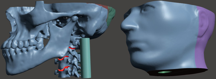
Designing the phantom was a multistep process that considered the anatomy to be included, weight of the phantom, field of view (FOV) in dental CBCT, the printer’s build volume and the size and location of an ion chamber for dosimetric measurements. Additionally, the phantom was designed so the horizontal plate of the palatine bone would be horizontal during use. Semi-automatic segmentation software (ITK-SNAP)25 was used to segment structures in the CT images with manual segmentation used where necessary. Contours of the skin, mandible, maxilla, orbits, vertebrae and intervertebral discs were exported as STL files and imported into MeshMixer. The meshes were then modified to meet the phantom considerations mentioned above. The final design of the phantom is shown in Figure 1 and extended from the cervical spine (C4 vertebrae) to midway through the orbits. Six distinct materials simulated the radiologic properties of different tissues. The contour of the skin was reshaped to properly enclose the boney anatomy. Overall dimensions were 22.5 × 15.2 × 11.4 cm3. Because the printer’s build volume was limited, i.e. 14.5 cm x 14.5 x 17.5 cm, the skin was designed as a two-piece shell (anterior and posterior pieces with the seam posterior to the temporomandibular joint (TMJ)) as shown in Figure 1. Similarly, the skull had a seam placed posterior to the TMJ. To allow for internal dosimetric measurements, a cylindrical cavity was located in the skin shell to accommodate an ion chamber. This cavity was positioned in the approximate location of the trachea and extended superiorly to the palate. The mandible, maxilla, orbits, vertebrae and intervertebral discs were designed to be assembled together and then inserted into the skin shell.
Figure 1.
Maxillofacial phantom (left) internal anatomical parts and (right) external skin shell designed with a cavity at the anatomical location of the trachea for the insertion of a six cc ion chamber. The spine has temporary guides attached to each vertebrae for proper assembly.
Results of evaluating the resin and urethane samples were used to select resins and powders necessary to mimic the radiological properties of tissues. The two pieces forming the skin shell were printed from white resin. These pieces were joined together by applying liquid resin (same white resin as they were made from) to the seam and then curing this resin using a hand-held UV diode (UV5TZ-405–15, Bivar, China). The skull, mandible and vertebrae were printed with clear resin that contained 60% CaCO3 and 15% SrCO3 powders. The two pieces of the skull were joined together in a similar manner as the skin. To secure the mandible and separate the teeth, epoxy containing 2% glass bubbles was used to fill the TMJ and mimicked the cartilage disc between the bones. The spine was printed with 80% CaCO3 and 7.5% SrCO3 to generate a CT number lower than compact bone. Intervertebral discs were printed from flexible resin. The spine comprised individual intervertebral discs and vertebrae held together with epoxy resin containing glass bubbles. To properly space, align and assemble the spine, temporary guides were incorporated into the vertebrae as shown in Figure 1. These guides were removed after the spine was assembled. The assembled internal parts of the phantom were inserted into the skin shell and the spaces between the bones and skin shell were filled with polyurethane rubber containing 3.5% glass bubbles. To reduce air bubbles, the urethane mixture was placed under vacuum for about one minute before it was poured into the shell. The liquid urethane then hardened to a firm solid.
Evaluation of phantom
Images of the phantom were acquired with the laboratory X-ray system and the diagnostic CT scanner (Somatom Definition Edge, Siemens). Dual energy CT scans using tube voltages of 80 kV and 140 kV were also acquired and the scanner’s software computed the effective atomic number (Zeff) of the materials over a small region of interest. To confirm the maxillofacial phantom was suitable, images and dosimetric measurements were acquired on CBCT (3D Accuitomo, Morita, Osaka, Japan) and panoramic/cephalometric (Veraviewepocs 2D, Morita, Osaka, Japan) imaging systems. A six cc ion chamber (Model 10 × 5–6, Radcal, Monrovia, CA) and 10 cm pencil chamber (Model 10 × 5–10.3, Radcal, Monrovia, CA) were used with a radiation monitor (Model 1515, Radcal, Monrovia, CA) for these measurements. The accuracy of the chambers and monitor was verified by comparing readings with a meter that had been calibrated by the manufacturer. Each ion chamber was inserted into the cavity of the phantom and secured in position using a stand and tape. The phantom was positioned with its chin in the imaging system’s holder and the imaging system lasers were used to align the phantom in a clinically representative position.
Results
Commercial materials
The densities and CT numbers obtained for the five commercial resins are given in Table 2. White, clear and dental model resins had similar CT numbers of around 120 HU. Flexible resin was found to have a CT number closer to 80 HU, which is similar to the desired values for intervertebral and TMJ discs. The CT number for rigid resin was the highest but was much too low to properly mimic bone (Table 1). All objects contained minor defects on the surface where the support rods attached. These defects were more pronounced and difficult to remove for the flexible resin. The X-ray and CT images showed no discernible internal defects for any of the commercial resins.
Table 2.
Density and CT number for 3D-printed test objects made with various commercial resins
| Resin Type | Density [g/cm3] | Average measured HU (SD) |
|---|---|---|
| White | 1.16 | 122 (6.8) |
| Clear | 1.17 | 116 (6.7) |
| Flexible | 1.12 | 79 (6.6) |
| Dental Model | 1.17 | 127 (7.0) |
| Rigid | 1.33 | 339 (6.6) |
HU, Hounsfield unit; SD, standard deviation.
HUs were measured using a clinical CT scanner (Somatom Definition Edge, Siemens) with 0.75 mm slice thickness, 120 kV tube potential, 350 mAs, reconstructed with B40s medium kernel.
Modified resins
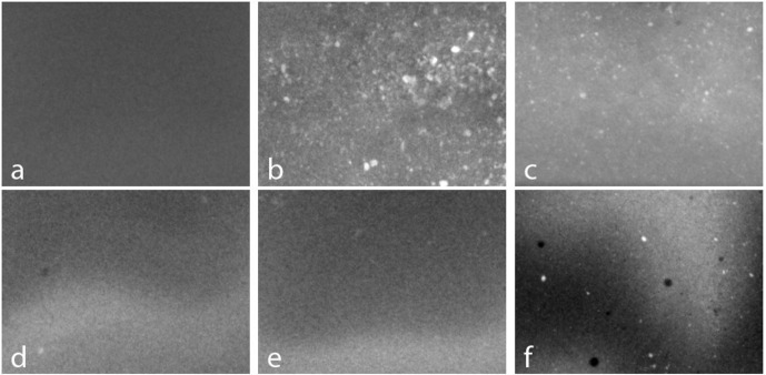
X-ray images of small samples of clear resin containing TiO2, ZnO and CaCO3 powders were acquired at 40kV and are shown in Figure 2. Visual inspection and X-ray imaging of the samples gave comparable results and showed how well the powders mixed into the resin. An X-ray image of the clear resin (Figure 2a) appears uniform as expected. In comparison, the samples containing TiO2 powder (Figure 2b) and ZnO powder (Figure 2c) are highly inhomogeneous and show that these powders did not easily mix into the resin. These powders also increased the time required for the resin to cure and the TiO2 sample cured with a rough surface. We found that CaCO3 powder was very easy to mix into the resin and this was confirmed by the uniform X-ray images shown in Figure 2d and e. Furthermore, the CaCO3 sample cured in a similar time to the clear resin which suggested this mixture was suitable for use in the printer. We also found that SrCO3 powder could be added along with CaCO3 powder, although there were a few residual clumps as shown in Figure 2f.
Figure 2.
Planar X-ray images of clear resin that contained: (a) no powders, (b) 10% TiO2, (c) 10% ZnO, (d) 10% CaCO3, (e) 20% CaCO3 and, (f) 3% SrCO3 and 90% CaCO3. Each image is 40 mm wide by 30 mm high. Smooth fluctuations in intensity are due to variations in sample thickness.
We found that test objects could be printed using clear resin containing CaCO3 powder with concentrations ranging from 10 to 120% by mass of clear resin, e.g. 100% means equal weights of CaCO3 powder and liquid resin. X-ray and CT images of these test objects showed no obvious defects. The corresponding CT numbers are given in Table 3 and show that adding CaCO3 powder increased the CT number to a maximum of 1158 ± 35 HU. However, at high concentrations of CaCO3 powder there were defects in the baseplate and supports which could lead to print failures. We found that higher CT numbers could be obtained by adding SrCO3 powder along with CaCO3 powder to the clear resin. This combination was found to print without difficulty. X-ray and CT images of test objects containing 60% CaCO3 powder and concentrations of SrCO3 powder ranging from 5 to 25% by mass of clear resin did not show any defects. The resulting CT numbers are given in Table 4 and show that the CT number could be increased up to 1918 ± 98 HU. The CT number also increased when the amount of SrCO3 was maintained at 5% and the CaCO3 concentration was increased from 60 to 80%. However, this only increased CT number from 992 ± 39 HU to 1165 ± 39 HU and suggests this approach would require too much CaCO3 powder to mimic bone, thus risking defects and print failures. For completeness, test objects printed using white resin containing glass bubbles showed the CT number could be reduced from 122 ± 6.8 HU to 15 ± 12 HU by increasing the concentration of the glass bubbles to 5%. Despite the large difference between the density of the glass bubbles and the density of the white resin the X-ray and CT images of the test objects did not shown any significant artefacts. Further increasing the amount of glass bubbles was not practical since the mixture became too viscous.
Table 3.
Radiographic and physical properties of 3D printed test objects made from clear resin containing various amounts of CaCO3 powder
| CaCO3 percent by mass of clear resin | Density [g/cm3] | Average measured HU (SD) |
|---|---|---|
| 10.0 | 1.22 | 245 (10) |
| 20.0 | 1.27 | 366 (14) |
| 30.0 | 1.31 | 411 (14) |
| 40.0 | 1.36 | 535 (15) |
| 50.0 | 1.43 | 645 (20) |
| 60.0 | 1.46 | 751 (22) |
| 70.0 | 1.52 | 833 (25) |
| 80.0 | 1.56 | 907 (26) |
| 90.0 | 1.60 | 975 (27) |
| 100 | 1.63 | 1019 (32) |
| 110 | 1.66 | 1077 (36) |
| 120 | 1.70 | 1158 (35) |
CaCO3 , calcium carbonate; HU, Hounsfield unit; SD, standard deviation.
HUs were measured using a clinical CT scanner (Somatom Definition Edge, Siemens) with 0.75 mm slice thickness, 120 kV tube potential, 350 mAs, reconstructed with B40s medium kernel.
Table 4.
Radiographic and physical properties of 3D printed test objects containing 60% CaCO3 and various amounts of SrCO3 powder
| SrCO3 percent by mass of clear resin | Density [g/cm3] | Average measured HU (SD) |
|---|---|---|
| 0.0 | 1.46 | 751 (22) |
| 5.0 | 1.49 | 992 (39) |
| 7.5 | 1.52 | 1136 (39) |
| 10.0 | 1.53 | 1260 (48) |
| 12.5 | 1.55 | 1421 (60) |
| 15.0 | 1.57 | 1531 (70) |
| 17.5 | 1.57 | 1631 (75) |
| 20.0 | 1.59 | 1721 (80) |
| 22.5 | 1.60 | 1805 (89) |
| 25.0 | 1.61 | 1918 (98) |
CaCO3, calcium carbonate; SrCO3, strontium carbonate; HU, Hounsfield unit; SD, standard deviation.
HUs were measured using a clinical CT scanner (Somatom Definition Edge, Siemens) with 0.75 mm slice thickness, 120 kV tube potential, 350 mAs, reconstructed with B40s medium kernel.
Modified polyurethane and epoxy
Adding the glass bubbles to polyurethane rubber and epoxy resin did not appreciably affect the ability of these two-part mixtures to cure, but it decreased the amount of time available to pour the materials after mixing. The polyurethane and epoxy resin samples had small air bubbles on their surfaces but otherwise were free of defects in X-ray and CT images. As shown in Table 5, adding the glass bubbles to PMC-780 dry urethane decreased the CT numbers from 38 ± 9.5 HU to −246 ± 8.8 HU. The addition of glass bubbles to the epoxy resin decreased the CT number from 182 ± 6.1 HU to −175 ± 13 HU without noticeably affecting its adhesive qualities.
Table 5.
Radiographic and physical properties for samples of PMC-780 Dry polyurethane rubber and epoxy containing various amounts of glass bubbles
| Modified PMC-780 Dry polyurethane rubber | Modified epoxy resin | |||
|---|---|---|---|---|
| Glass bubbles percent by mass of urethane | Density [g/cm3] | Average measured HU (SD) | Glass bubble percent by mass of epoxy | Average measured HU (SD) |
| 0.0 | 1.06 | 38 (9.5) | 0.0 | 182 (6.1) |
| 2.5 | 0.96 | −63 (11) | 2.0 | 100 (7.2) |
| 3.5 | 0.92 | −114 (8.0) | 3.0 | 28 (7.2) |
| 5.0 | 0.88 | −133 (9.2) | 4.0 | 24 (6.5) |
| 7.5 | 0.81 | −193 (10) | 6.0 | −50 (7.5) |
| 10 | 0.76 | −246 (8.8) | 8.0 | −130 (6.8) |
| 10 | −175 (13) | |||
HU, Hounsfield unit; SD, standard deviation.
HUs were measured using a clinical CT scanner (Somatom Definition Edge, Siemens) with 0.75 mm slice thickness, 120 kV tube potential, 350 mAs, reconstructed with B40s medium kernel.
Maxillofacial phantom
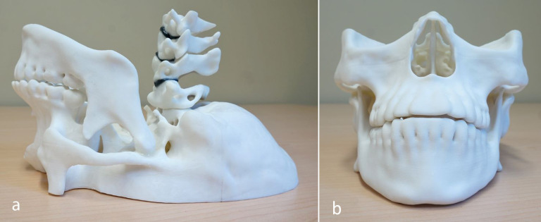
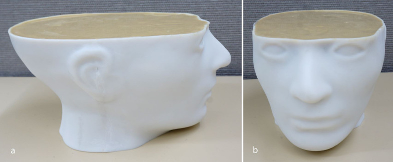
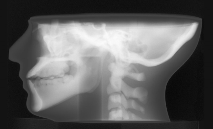
The materials and powders chosen to mimic the radiological properties of the tissues present in the maxillofacial phantom are given in Table 6. The assembled internal parts of the phantom are shown in Figure 3, with the completed phantom shown in Figure 4. An X-ray image of the phantom is given in Figure 5, and it can be seen that the overall appearance and anatomy mimic a typical patient. However, CT images (Figure 6) demonstrated small non-uniformities as well as a few small air bubbles in the soft tissue mimic (polyurethane). The resulting CT numbers and effective atomic numbers are given in Table 6. The measured CT numbers were very close to the expected values listed in Table 6. Dual energy CT found that the measured Zeff of the mandible, skull and soft tissues were higher than the published values shown in Table 1. However, the spine had a Zeff of 13.4, which was lower than the published value of bone of 13.8.
Table 6.
Materials and powders used to simulate the radiographic properties of tissues in the maxillofacial phantom
| Tissue | Material | Powder added | Expected HU | Average measured HU (SD) | Measured Zeff |
|---|---|---|---|---|---|
| Bone (skull) | Clear resin | 60% CaCO3 & 15% SrCO3 | 1500 | 1509 (115) | 15.4 |
| Bone (vertebrae) | Clear resin | 80% CaCO3 & 7.5% SrCO3 | 1000 | 1062 (80) | 13.4 |
| Soft tissue (fat) | Urethane rubber | 3.5% Glass bubbles | −95 | −54 (22) | 7.5 |
| Intervertebral disc | Flexible resin | N/A | 80 | 139 (64) | 7.9 |
| TMJ disc | Epoxy resin | 2% Glass bubbles | 100 | 126 (35) | 9.0 |
| Skin | White resin | N/A | 120 | 117 (36) | 6.9 |
HU, Hounsfield unit; SD, standard deviation; Zeff, effective atomic number; CaCO3, calcium carbonate; SrCO3, strontium carbonate; TMJ, temporomandibular joint.
Values were measured using a clinical CT scanner (Somatom Definition Edge, Siemens) with 0.75 mm slice thickness, 120 kV tube potential, 350 mAs reconstructed with B40s medium kernel. Effective atomic numbers were obtained using dual energy CT scan with 80 kV and 140 kV tube potentials.
Figure 3.
Internal 3D printed parts of maxillofacial phantom assembled using modified epoxy resin (a) sideview and (b) front view including mandible, spine (C1–C4 vertebrae with intervertebral discs) and maxilla.
Figure 4.
(a) Side view and (b) front view of maxillofacial phantom with internal 3D printed parts in 3D printed skin filled with modified polyurethane rubber and assembled with modified epoxy resin
Figure 5.
Planar X-ray image of maxillofacial phantom acquired at 90 kV.
Figure 6.
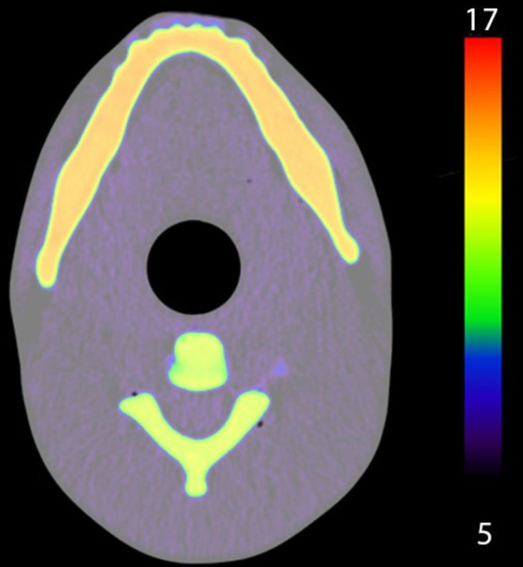
Axial dual energy CT image of maxillofacial phantom, colour indicates the effective atomic number range from 5 to 17.
Dental imaging and dosimetry
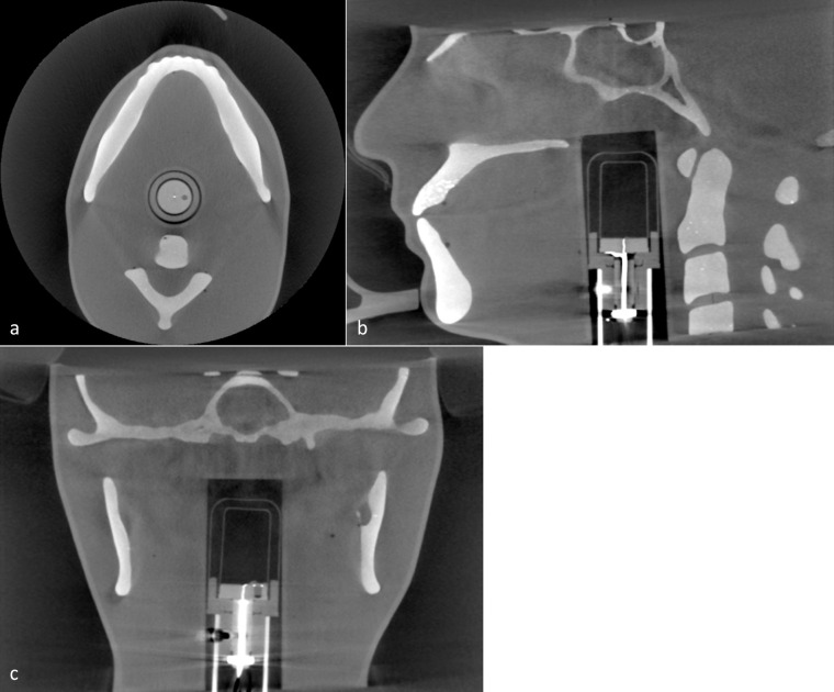
Acquired CBCT images are given in Figure 7 and show that the phantom mimics the typical anatomy seen in a patient image. Bright spots in the maxillary teeth suggest the SrCO3 powder did not fully mix into the resin. The sensitive volume of the six cc ion chamber can be seen and is centrally located in the image. Using the six cc ion chamber, dose measurements were acquired for the largest (170 × 120 mm) and smallest (40 × 40 mm) FOV sizes available. For the largest FOV, 360⁰ standard and Hi-Fi images were found to have doses of 4.1 mGy and 5.4 mGy respectively. For the smallest FOV, standard images were taken using 180⁰ and 360⁰ rotations, giving measured doses of 1.6 mGy and 2.9 mGy respectively.
Figure 7.
a) Axial, (b) sagittal and (c) coronal CBCT image of maxillofacial phantom with 6cc ion chamber inserted for dosimetric measurements.
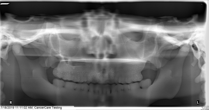
A panoramic image is given in Figure 8 and appears representative of a typical patient with the horizontal plate of the palatine bone approximately horizontal. With standard panoramic imaging selected and automatic exposure control (AEC) enabled, measurements using the six cc ion chamber and 10 cm pencil chamber resulted in doses of 0.19 mGy and 0.24 mGy respectively. With standard panoramic imaging selected but using manual technique settings of 80 kV and 8.0 mA resulted in a dose of 0.58 mGy measured with the 10 cm pencil chamber.
Figure 8.
Panoramic image of maxillofacial phantom for standard mandible image using automatic exposure control.
Discussion
Using 3D printing techniques, we designed and constructed an anthropomorphic phantom for use in dental radiography. It mimicked the anatomy and radiological properties of a typical adult patient. For 3D-printed bone mimics, the CT numbers could be increased by adding CaCO3 powder, which mixed easily and uniformly into the clear resin. However, the CT number could only be increased to about 1100 before the large amount of powder made printing impossible. Adding SrCO3 powder along with CaCO3 powder enabled much higher CT numbers to be obtained although at the expense of increasing the effective atomic number. The resulting bone mimics were easy to print with consistent quality but the geometric fidelity was noticeably reduced. The dimensions of the test objects confirmed the overall accuracy was still reasonable and suitable for this application. Although not used for the phantom, adding glass bubbles to the resin gave prints with a reduced CT number that could mimic muscle. However, the mixture needed to be mixed often and thoroughly to prevent separation while printing. Additionally, the resulting test objects had a gritty surface and it was more difficult to remove blemishes left by the supports. A major limitation of this approach is that it was extremely inconvenient. To ensure the mixture of resin and powder was uniform, the printer’s tank was refilled manually, which required closely monitoring the printer during the course of very long print times, e.g. 14 h. Adding large quantities of powder increased the probability that a print would fail, which also required the printer be closely monitored. SLA printer technology was used here but FFF printers are extremely popular with a wide range of filament materials available. In principle, it is possible to make filaments for FFF but this requires specialised equipment for mixing, extruding, cooling and spooling.23 In comparison, the photoreactive liquid resin was easily modified by adding powders.
The CT numbers of polyurethane rubber and epoxy resin were decreased by adding glass bubbles. Overall, this approach worked well and the materials cured properly. One limitation was that adding glass bubbles required more mixing and reduced the time available to use the mixture, i.e. the pot life was reduced. The epoxy resin pot life was increased by preparing it in small batches. In principle, the pot life could be extended by cooling the materials before mixing, although this was not done here. We found that that the urethane rubber had CT numbers that depended somewhat on which manufacture’s batch was used. This resulted in small differences between the expected and measured CT numbers. Overall, we obtained tissue-mimicking photoreactive resins, polyurethane rubber and epoxy resins that reproduced a wide range of CT numbers. These results were applied to produce an anthropomorphic maxillofacial phantom using a combination of 3D prints, polyurethane rubber and epoxy resin that matched the CT number of the tissue they mimicked (Table 1).
Because the phantom was based on CT images of a real skull, a number of alterations were made. These included removing a large defect in the mandible by replacing this region with a mirrored copy from the contralateral side. Small structures and structures that were free floating were removed since these would be lost or broken off in the post-processing. Additionally, the surface meshes exported from the segmentation software were smoothed to reduce stair-step artefacts but this also obscured fine details. The teeth were noticeably effected by smoothing and required careful segmentation to obtain an acceptable fidelity. The skin contour was a simplification with flattened ears and its overall shape required manipulation to fit the somewhat asymmetric skull. Judging and manipulating the facial region was a difficult task since in some areas the skin-to-bone distances needed to be quite thin and the skin was printed with a thickness of 2 mm that had to be accounted for. It was also necessary to be mindful of how the phantom would be assembled.
Due to the limitation of the printer’s small build volume, the skull and skin had to be printed as two pieces each that were then assembled. Because the skin was printed as two hollow shells, there was minor warping and the two constituent pieces did not aligning perfectly without additional post-processing. Warping would likely have been reduced if temporary support rods were added before the skin was printed. Furthermore, the skull and mandible used the same CT number for everything. In future designs the teeth could be printed separately with a higher CT number (e.g. increased SrCO3 concentration) and inserted into the mandible and maxilla to better mimic an actual patient. The vertebrae were printed with a CT number that mimicked the average CT number of a vertebrae. In reality, the cortical bone on the periphery of the vertebrae have a high CT number of approximately 1500 HU but the inner (spongy) calcaneus bone has a much lower CT number of approximately 500 HU. In the future, rather than being printed as a solid part, the vertebrae (and mandible) could be printed hollow and filled with modified polyurethane to simulate the trabecula and marrow cavity. Flexible resin was chosen for the intervertebral discs even though the CT number was not a perfect mimic. However, the pliability of the flexible resin allowed force to be applied when gluing the disc in place, which made assembly easier and eliminated air gaps.
Images of the phantom acquired using dental CBCT and panoramic imaging showed appropriate anatomy with proper orientation of the internal structures, good contrast between tissues and a good fit of the six cc ion chamber. Some speckle was evident on the upper teeth in the panoramic images from the SrCO3 powder not mixing in entirely. This is not present in other parts of the print, suggesting that the last batch of resin used to finish the print was not fully mixed prior to adding it to the tank. The phantom functioned as intended for quickly making reference dose measurements. For CBCT, the highest dose was measured for the Hi-Fi scan, which took longer to acquire than the standard protocol and is typically used when sharper images are required. Using a small FOV reduced the dose considerably (by about 70%) which is expected since smaller FOVs are typically used to acquire high resolution images while minimising the X-ray dose to the patient. The dose for the full 360⁰ rotation was more than double that of the 180⁰ scan, possibly due to the mandible shielding the chamber for part of the rotation. For the panoramic images, the dose using manual technique settings was much (2.4 times) greater than when the AEC was used. The discrepancy in measurements acquired with the 6 cc and 10 cm chambers was unexpected and requires further investigation.
Using 3D-printing technology leads to a very flexible design. The segmentation and design steps were time-consuming, but the resulting files can be easily modified to change the shape and size of the phantom as needed. For example, a larger or smaller phantom could be made with modest effort. The materials and powders characterised here can also be used to make phantoms that mimic other anatomy, e.g. a forearm.26 Ideally, other resins and powders, such as BaSO4, would be evaluated and the results made known. Although this phantom was designed for a specific 6 cc ion chamber, a 10 cm ion chamber with a smaller diameter was inserted into the cavity. If a more secure fit was desired, it would be straightforward to 3D-print a suitable build-up cap or holder to accommodate a smaller chamber. It would also be easy to make entrance skin dose measurements with a chamber positioned in front of the teeth by using a suitable stand. Thermoluminescent dosemeter (TLD) chips are commonly used to in conjunction with phantoms to measure absorbed organ and effective doses for a range of dental systems and protocols.27,28 For example, Ludlow et al28 measured absorbed and effective doses at 24 sites within a commercial adult head phantom and the topical sites of the eyes and pituitary gland. Although our phantom did not contain internal cavities to accommodate TLD chips, it would be straightforward to change the design. For example, cylindrical cavities along the superior–inferior direction could be added to the design and a second phantom built. Corresponding cylindrical holders for the TLDs could easily be printed from resin or molded from urethane.
Conclusion
We characterised SLA 3D printing technology with the aim of creating detailed phantoms using materials that simulated the radiological properties of body tissues. In conclusion, SLA printer technology was used to produce an anthropomorphic phantom containing complex anatomical parts that mimicked the appropriate CT numbers. Using this approach, complex phantoms mimicking different size patients and diverse anatomy can be produced and the files shared so other facilities can make their own copies.
Footnotes
Acknowledgements: The authors extend thanks to Dr Meredith Brownlee, Division Head of Oral and Maxillofacial Radiology at the University of Manitoba and Bryan McIntosh, Radiation Protection Officer at CancerCare Manitoba for their expertise in dental imaging and dosimetry, as well as funding provided by the Manitoba Graduate Scholarship.
Funding: This research was supported by the Manitoba Graduate Scholarship provided by the Government of Manitoba.
Contributor Information
Sawyer Rhae Badiuk, Email: sbadiuk3@uwo.ca.
David K Sasaki, Email: dsasaki@cancercare.mb.ca.
Daniel W Rickey, Email: Drickey@cancercare.mb.ca.
REFERENCES
- 1.Hayashi T, Arai Y, Chikui T, Hayashi-Sakai S, Honda K, Indo H, et al. Clinical guidelines for dental cone-beam computed tomography. Oral Radiol 2018; 34: 89–104. doi: 10.1007/s11282-018-0314-3 [DOI] [PubMed] [Google Scholar]
- 2.Carter JB, Stone JD, Clark RS, Mercer JE. Applications of cone-beam computed tomography in oral and maxillofacial surgery: an overview of published indications and clinical usage in United States academic centers and oral and maxillofacial surgery practices. Journal of Oral and Maxillofacial Surgery 2016; 74: 668–79. doi: 10.1016/j.joms.2015.10.018 [DOI] [PubMed] [Google Scholar]
- 3.Doses LAG. Benefits, safety, and risks in oral and maxillofacial diagnostic imaging. Health Physics 2019; 116: 163–9. [DOI] [PubMed] [Google Scholar]
- 4.Pauwels R. Cone beam CT for dental and maxillofacial imaging: dose matters: Table 1. Radiat Prot Dosimetry 2015; 165(1-4): 156–61. doi: 10.1093/rpd/ncv057 [DOI] [PubMed] [Google Scholar]
- 5.Colceriu-Șimon IM, Băciuț M, Ştiufiuc RI, Aghiorghiesei A, Ţărmure V, Lenghel M. Clinical indications and radiation doses of cone beam computed tomography in orthodontics. Med Pharm Reports 2019; 92: 351–64. [DOI] [PMC free article] [PubMed] [Google Scholar]
- 6.Torgersen GR, Hol C, Møystad A, Hellén-Halme K, Nilsson M. A phantom for simplified image quality control of dental cone beam computed tomography units. Oral Surg Oral Med Oral Pathol Oral Radiol 2014; 118: 603–11. doi: 10.1016/j.oooo.2014.08.003 [DOI] [PubMed] [Google Scholar]
- 7.Pauwels R, Stamatakis H, Manousaridis G, Walker A, Michielsen K, Bosmans H, et al. Development and applicability of a quality control phantom for dental cone-beam CT. J Appl Clin Med Phys 2011; 12: 245–60. doi: 10.1120/jacmp.v12i4.3478 [DOI] [PMC free article] [PubMed] [Google Scholar]
- 8.Winslow JF, Hyer DE, Fisher RF, Tien CJ, Hintenlang DE. Construction of anthropomorphic phantoms for use in dosimetry studies. Journal of Applied Clinical Medical Physics 2009; 10: 195–204. doi: 10.1120/jacmp.v10i3.2986 [DOI] [PMC free article] [PubMed] [Google Scholar]
- 9.Oenning AC, Salmon B, Vasconcelos KdeF, Pinheiro Nicolielo LF, Lambrichts I, Sanderink G, et al. DIMITRA paediatric skull phantoms: development of age-specific paediatric models for dentomaxillofacial radiology research. Dentomaxillofac Radiol 2018; 118: 20170285–6. doi: 10.1259/dmfr.20170285 [DOI] [PMC free article] [PubMed] [Google Scholar]
- 10.Iwai K, Hashimoto K, Nishizawa K, Sawada K, Honda K. Evaluation of effective dose from a RANDO phantom in videofluorography diagnostic procedures for diagnosing dysphagia. Dentomaxillofac Radiol 2011; 40: 96–101. doi: 10.1259/dmfr/51307488 [DOI] [PMC free article] [PubMed] [Google Scholar]
- 11.Yamauchi-Kawaura C, Fujii K, Akahane K, Yamauchi M, Narai K, Aoyama T, et al. Development of age-specific Japanese head phantoms for dose evaluation in paediatric head CT examinations. Radiat Prot Dosimetry 2015; 163: 188–201. doi: 10.1093/rpd/ncu155 [DOI] [PubMed] [Google Scholar]
- 12.Najafi M, Teimouri J, Shirazi A, Geraily G, Esfahani M, Shafaei M. Technical note: construction of heterogeneous head phantom for quality control in stereotactic radiosurgery. Med Phys 2017; 44: 5070–4. doi: 10.1002/mp.12496 [DOI] [PubMed] [Google Scholar]
- 13.Tejo-Otero A, Buj-Corral I, Fenollosa-Artés F. 3D printing in medicine for preoperative surgical planning: a review. Ann Biomed Eng 2020; 48: 536–55. doi: 10.1007/s10439-019-02411-0 [DOI] [PubMed] [Google Scholar]
- 14.Langridge B, Momin S, Coumbe B, Woin E, Griffin M, Butler P. Systematic review of the use of 3-dimensional printing in surgical teaching and assessment. J Surg Educ 2018; 75: 209–21. doi: 10.1016/j.jsurg.2017.06.033 [DOI] [PubMed] [Google Scholar]
- 15.Ganguli A, Pagan-Diaz GJ, Grant L, Cvetkovic C, Bramlet M, Vozenilek J, et al. 3D printing for preoperative planning and surgical training: a review. Biomed Microdevices 2018; 20: 65. doi: 10.1007/s10544-018-0301-9 [DOI] [PubMed] [Google Scholar]
- 16.Tino R, Yeo A, Leary M, Brandt M, Kron T. A systematic review on 3D-printed imaging and dosimetry phantoms in radiation therapy. Technol Cancer Res Treat 2019; 18: 1–14. doi: 10.1177/1533033819870208 [DOI] [PMC free article] [PubMed] [Google Scholar]
- 17.Statkiewicz-Sherer MA, Visconti PJ, Ritenour ER, Haynes KW. Radiation protection in medical radiography. 8th edn. Mosby; 2018. [Google Scholar]
- 18.Ehler E, Craft D, Rong Y. 3D printing technology will eventually eliminate the need of purchasing commercial phantoms for clinical medical physics QA procedures. J Appl Clin Med Phys 2018; 19: 8–12. doi: 10.1002/acm2.12392 [DOI] [PMC free article] [PubMed] [Google Scholar]
- 19.Homolka P, Figl M, Wartak A, Glanzer M, Dünkelmeyer M, Hojreh A, et al. Design of a head phantom produced on a 3D rapid prototyping printer and comparison with a RANDO and 3M lucite head phantom in eye dosimetry applications. Phys Med Biol 2017; 62: 3158–74. doi: 10.1088/1361-6560/aa602c [DOI] [PubMed] [Google Scholar]
- 20.Gear JI, Cummings C, Craig AJ, Divoli A, Long CDC, Tapner M, et al. Abdo-Man: a 3D-printed anthropomorphic phantom for validating quantitative SIRT. EJNMMI Phys 2016; 3: 17. doi: 10.1186/s40658-016-0151-6 [DOI] [PMC free article] [PubMed] [Google Scholar]
- 21.Craft DF, Howell RM. Preparation and fabrication of a full‐scale, sagittal‐sliced, 3D‐printed, patient‐specific radiotherapy phantom. J Appl Clin Med Phys 2017; 18: 285–92. doi: 10.1002/acm2.12162 [DOI] [PMC free article] [PubMed] [Google Scholar]
- 22.Kim M-J, Lee S-R, Lee M-Y, Sohn JW, Yun HG, Choi JY, et al. Characterization of 3D printing techniques: toward patient specific quality assurance spine-shaped phantom for stereotactic body radiation therapy. PLoS One 2017; 12: 5. doi: 10.1371/journal.pone.0176227 [DOI] [PMC free article] [PubMed] [Google Scholar]
- 23.Hazelaar C, van Eijnatten M, Dahele M, Wolff J, Forouzanfar T, Slotman B, et al. Using 3D printing techniques to create an anthropomorphic thorax phantom for medical imaging purposes. Med Phys 2018; 45: 92–100. doi: 10.1002/mp.12644 [DOI] [PubMed] [Google Scholar]
- 24.Hamedani BA, Melvin A, Vaheesan K, Gadani S, Pereira K, Hall AF. Three-Dimensional printing CT-derived objects with controllable radiopacity. J Appl Clin Med Phys 2018; 19: 317–28. doi: 10.1002/acm2.12278 [DOI] [PMC free article] [PubMed] [Google Scholar]
- 25.Yushkevich PA, Piven J, Hazlett HC, Smith RG, Ho S, Gee JC, et al. User-guided 3D active contour segmentation of anatomical structures: significantly improved efficiency and reliability. Neuroimage 2006; 31: 1116–28. doi: 10.1016/j.neuroimage.2006.01.015 [DOI] [PubMed] [Google Scholar]
- 26.Badiuk S, Sasaki D, Rickey D. Anthropomorphic phantoms using 3D-printing techniques. Medical Physics 2019; 46: 5382. [Google Scholar]
- 27.Ludlow JB, Davies-Ludlow LE, Brooks SL. Dosimetry of two extraoral direct digital imaging devices: NewTom cone beam CT and Orthophos plus Ds panoramic unit. Dentomaxillofac Radiol 2003; 32: 229–34. doi: 10.1259/dmfr/26310390 [DOI] [PubMed] [Google Scholar]
- 28.Ludlow JB, Davies-Ludlow LE, Brooks SL, Howerton WB. Dosimetry of 3 CBCT devices for oral and maxillofacial radiology: CB Mercuray, NewTom 3g and i-CAT. Dentomaxillofac Radiol 2006; 35: 219–26. doi: 10.1259/dmfr/14340323 [DOI] [PubMed] [Google Scholar]


