Abstract
We report a facile atmospheric plasma reaction synthesis of PtxFe1−x alloys with the different Pt/Fe stoichiometric ratio in PtxFe1−x alloys on graphene (G) as efficient counter electrode (CE) materials and atmospheric plasma reaction synthesised TiO2 nanoparticles/G as photoanode in dye-sensitized solar cells (DSSCs). Well-distributed PtxFe1−x nanoparticles or TiO2 nanoparticles on the G surface were obtained. Remarkably, DSSCs prepared by the Pt0.7Fe0.3/G CE have much higher catalytic activity and stable durability than Pt1Fe0/G CE. The as-synthesized Pt0.7Fe0.3/G CE exhibits the largest value of |Jred| = 1.479 mA and the lowest value of Rct = 2.86 Ω. With the Pt0.7Fe0.3/G as CE and TiO2/G as the photoanode, the DSSC can deliver an overall power conversion efficiency (PCE) of 10.13%, which is significantly higher than the 9.72% of the expensive Pt1Fe0/G counterpart. The obtained results indicate that the PtxFe1−x/G nanohybrids fabricated using atmospheric plasma reaction exhibited potential as a reference for next generation CE materials in highly efficient DSSCs. We believe that this work provides an effective strategy for optimizing Pt utilization for the low-cost and efficient application of DSSCs.
The DSSCs using a Pt0.7Fe0.3/G CE and TiO2 nanoparticles/G photoanode obtained a PCE of 10.13%.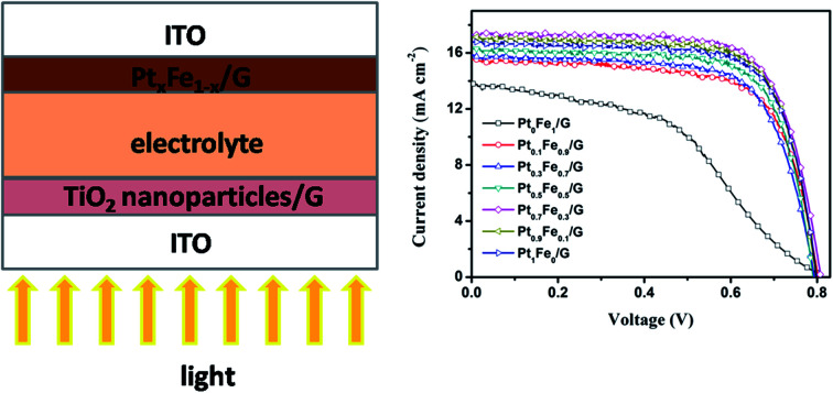
1. Introduction
The dye-sensitized solar cells (DSSCs) are considered to be a promising alternative to commercial silicon solar cells.1–3 The reduction of I3− to I− ions is critical in efficient DSSC devices. Generally, the precious platinum (Pt) has been employed as the best counter electrode (CE) material due to its high electrical conductivity and superior electrocatalytic activity to the I3−/I− redox system.4 In typical standard DSSCs, a high Pt loading is required in order to improve the CE properties, which results in increases in the cost of DSSCs. Therefore, one of the best approaches to develop effectively and low-cost CE materials are by reducing precious Pt without compromising the electrochemical performance. Furthermore, improvement of the long-term stability of Pt CE under corrosion in the electrolyte is still a significant obstacle. For this reason, the reduction of particle size of Pt catalyst to nanoscale and dispersing them on proper support matrix are adopted. Carbon materials in various forms like graphene (G), graphite and carbon black are still the mostly used materials for DSSCs because of their high conductivity, availability and low cost.5–7 Moreover, increasing the intrinsic catalytic activity of Pt by alloying it with transition metals (Ni, Co, Fe, Mo, and Cu) is also a promising method.8–10 Hence, under the background of developing efficient low-cost hybrid CE materials, several PtM alloys/G (M = Ni, Co, Pd, Fe, Mo, Cu, Cr, Sn, and Ru) as materials for CEs have been developed, and these study results have demonstrated them to be good CE alternatives to traditional Pt electrode.11–13 In searching for efficient low-Pt nanohybrid CEs, in the current work, we present here the synthesis of PtxFe1−x alloy/G nanohybrid CEs and the optimization of PtxFe1−x/G for highly photovoltaic efficiency of DSSCs. It is expected that the optimized PtxFe1−x/G nanocomposite will combine both good conductivity and high catalytic activity in the reduction reaction of I−/I3−.
For coating the PtM alloys (M = Ni, Co, Pd, Fe, Mo, Cu, Cr, Sn, and Ru) on a conductive substrate, several conventional methods (such as sputtering, electrochemical deposition and hydro-thermal chemical reduction) have been developed.11–13 However, these methods usually need high temperatures and vacuum condition. To overcome these disadvantages, plasma technology has been developed to synthesize bimetallic nanoparticles.13–16 Atmospheric plasma reaction technology is operated at under room temperature and pressure conditions. In the atmospheric plasma reaction process, some species in the aqueous solution near the plasma can be transformed into highly reactive species, which can rapidly react with other surrounding highly reactive species to form products.13,15 This plasma technology is particularly compatible with the fabrication process of DSSCs, which also requires no vacuum system. This is one main advantage of DSSCs over other photovoltaic cells.17–21 It is important to note that this approach only requires a short aging time for reduction and nearly room temperature. One of the main motivations in this work is to overcome the process restrictions previously mentioned, especially high temperature and low pressure. Here, we present a new process to efficiently synthesize G supported PtxFe1−x alloy nanoparticles using a atmospheric plasma reaction technology at near room temperature under atmospheric pressure.
For the chemical stability and the rapid injection rate of electrons from excited dye into TiO2 conduction band, TiO2 is normally used for photoanode material of DSSCs to load dye and transport electrons.22,23 But the non-favorable high recombination reaction rates of photo-induced electrons and holes between the interface of TiO2 and electrolyte hinder the improvement of the power conversion efficiency (PCE) of the DSSCs performance.24–26 Thus, TiO2 matrix in combination with a thin conducting layer (such as G) which can reduce the recombination of photo-induced charge carrier and accelerate the electron transport is utilized as effective photoanode. The incorporation of G in TiO2-based composite photoanodes to enhance the efficiency of the DSSCs has been an active issue among researchers over the last decade.27–32 Although many groups have already used the PtM alloys/G CEs and TiO2-based composite photoanodes separately to enhance the efficiency of DSSCs, in this work, we used both PtM alloys/G CE and TiO2/G photoanode simultaneously to improve the efficiency of devices.
Herein, PtxFe1−x alloy/G nanohybrid CE material and TiO2/G photoanode material were prepared by a facile atmospheric plasma reaction route. It is expected that PtxFe1−x alloy/G nanohybrids with a small amount of Pt will combine both high conductivity and high catalytic activity to reduce triiodide to iodide ions at the CE. As the results, the highest electrical conductivity and electrocatalytic ability were obtained for Pt0.7Fe0.3/G electrode. Thus, a PCE of 10.13% was obtained for the DSSC device with Pt0.7Fe0.3/G CE and TiO2/G photoanode.
2. Experimental
2.1. Synthesis of the PtFe alloy/G
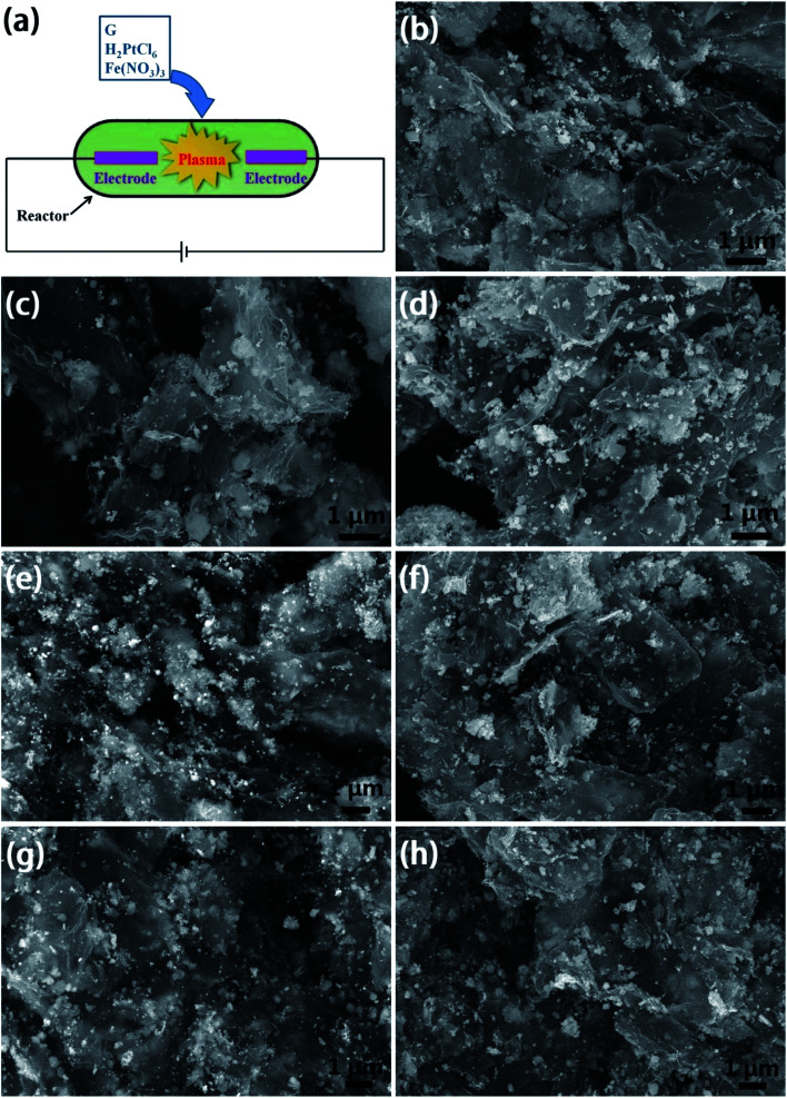
G nanosheets and active carbon (AC) are purchased from Tanfeng Tech. Inc. (Suzhou, China). Other reagents are purchased from Sigma-Aldrich Shanghai Trading Co Ltd. and used without further purification. Pt/G, Fe/G, and PtFe alloy/G composites were synthesized by an atmospheric plasma reaction method using an AC plasma system. Fig. 1a shows a schematic diagram of the plasma system. Seven PtxFe1−x/G composites with different volume ratios of Fe to Pt precursors were prepared for comparison. Firstly, 30 mg G was mixed thoroughly with 20 mL ethanol and ultrasonicated for 1 h to obtain a G dispersion solution. Secondly, two solutions of 1 mM of H2PtCl6·xH2O and 1 mM of Fe(NO3)3 in deionized water were prepared first. Then, the solutions were mixed at different volume ratios of 1 : 0, 0.9 : 0.1, 0.7 : 0.3, 0.5 : 0.5, 0.3 : 0.7, 0.1 : 0.9, and 0 : 1, and the total volume of the mixture was 50 mL. Thirdly, 20 mL G dispersion solution and 3 mL hydrazine hydrate were added in the above solution and stirred for 10 min. The reaction mixture was then transferred into the reactor of the plasma system at 200 W for 1 h. On completion, the black solid product was centrifuged, washed twice with DI water, followed by ethanol washing, and dried at 80 °C in vacuum. We denoted the CEs by Pt0Fe1/G, Pt0.1Fe0.9/G, Pt0.3Fe0.7/G, Pt0.5Fe0.5/G, Pt0.7Fe0.3/G, Pt0.9Fe0.1/G, and Pt1Fe0/G.
Fig. 1. (a) Schematic diagram of the plasma system. SEM images of CEs: (b) Pt0Fe1/G, (c) Pt0.1Fe0.9/G, (d) Pt0.3Fe0.7/G, (e) Pt0.5Fe0.5/G, (f) Pt0.7Fe0.3/G, (g) Pt0.9Fe0.1/G, and (h) Pt1Fe0/G.
2.2. Synthesis of the TiO2 nanoparticles/G composite
Firstly, 20 mL of deionized water (DW) and 40 mL isopropyl alcohol were mixed together using magnetic stirrer until a homogeneous solution formed. Then, 6.0 g of titanium sulfate (Ti(SO4)2) was added under strong stirring till a uniform solution achieved. Secondly, 20 mL of G dispersion solution was slowly added to the above mixture under stirring. The reaction mixture was then transferred into the reactor of the plasma system at 150 W for 1 h. Finally, as-prepared TiO2 nanoparticles/G were centrifuged, rinsed and overnight dried at 90 °C. The characterization results (see Fig. S1 and S2 in ESI†) and the corresponding discussion of the TiO2 nanoparticles/G composite are shown in ESI.†
2.3. Electrode preparation, fabrication of DSSCs, characterization and measurements
Electrode preparation, fabrication of DSSCs, characterization and measurements are detailed in ESI.†
3. Results and discussion
3.1. Characterization of the PtxFe1−x alloy/G nanohybrid materials
The stoichiometric ratio of Pt and Fe in PtxFe1−x alloy/G was controlled to obtain an efficient PtxFe1−x alloy/G CE with both good catalytic activity and electrical conductivity. Fig. 1b–h shows the SEM images of Pt0Fe1/G, Pt0.1Fe0.9/G, Pt0.3Fe0.7/G, Pt0.5Fe0.5/G, Pt0.7Fe0.3/G, Pt0.9Fe0.1/G, and Pt1Fe0/G samples, respectively. It can be seen that the PtxFe1−x NPs are firmly wrapped on the 2D like G nanosheets with a high surface coverage and high loading of PtxFe1−x NPs. G nanosheets associated with each other are clearly visible in these figures. Such 3D-network architecture of G nanosheets with large accessible surface area and high PtxFe1−x particle coverage on the surface is favorable for electrochemical catalytic activity of PtxFe1−x alloy/G electrode for DSSC, because it provides numerous channels for rapid diffusion of I3− ions across the PtxFe1−x/G thin layer, and this is a major requirement for the high electrochemical catalytic activity in the PtxFe1−x/G CEs.
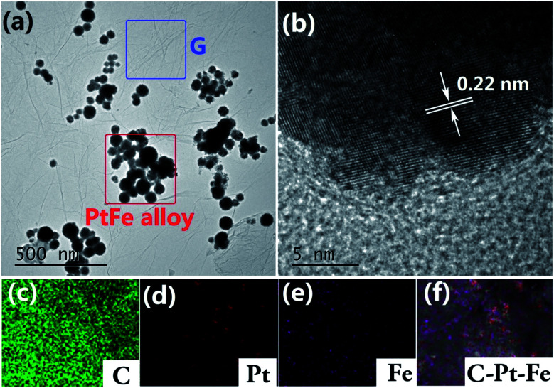
The TEM and HRTEM measurements were conducted to provide in-depth information about the morphology and structure of the PtxFe1−x/G. It should be mentioned that G nanosheets were used as a support for PtxFe1−x NPs to simplify sample preparation steps. Take Pt0.7Fe0.3/G for instance, the Fig. 2a displays the morphology of as-synthesized Pt0.7Fe0.3/G, and it shows the Pt0.7Fe0.3 nanoparticles of size around 50 nm immobilized on the graphene surface. The clear lattice fringes (Fig. 2b) with atomic spacing vale (0.22 nm) are equivalent to (1 1 1) plane of a chemically ordered face centered tetragonal PtFe phase.33 To determine the position of atoms on Pt0.7Fe0.3/G electrode, elemental mapping was carried out to investigate the distribution of different species (Fig. 2c–f). Elemental mapping images confirm the presence of different elements (C, Pt and Fe) and also reveal the uniform distribution of C, Pt and Fe at the electrode surface. Fig. S3† shows the Raman spectrum of Pt0.5Fe0.5/G. It can be seen clearly that the peaks mainly originated from G. Raman spectrum of Pt0.5Fe0.5/G displayed distinct G-band at 1580 cm−1 and D-band peak at 1350 cm−1. The intensity ratio ID/IG is about 1.12, illustrating a high defective structure of the used G.34 We provided a study on the optimization of the chemical structure of the PtxFe1−x/G composites in order to enhance both the electrical conductivity of CE and electrochemical catalytic activity for the reduction of I3−. Therefore, a set of CEs based on PtxFe1−x/G composites prepared with different Pt precursor volume ratio was fabricated. It should be mentioned that the molar ratios of [Fe]/[Pt] in the reaction precursors did not precisely match the Pt to Fe atomic ratios in corresponding to PtxFe1−x alloy particles, as determined by the XPS analysis. The chemical compositions of the PtxFe1−x/G samples were evaluated to be Pt0Fe1/G, Pt0.43Fe0.57/G, Pt0.56Fe0.44/G, Pt0.80Fe0.20/G, Pt0.82Fe0.18/G, Pt0.89Fe0.11/G, and Pt1Fe0/G (Table S1†).
Fig. 2. (a and b) TEM images showing the Pt0.7Fe0.3/G; elemental mapping of Pt0.7Fe0.3/G: (c) C, (d) Fe, (e) Pt and (f) C–Pt–Fe.
The PtxFe1−x/G nanohybrids are subjected to XPS measurement to determine the composition and electronic state of the elements, and the corresponding results are presented in Fig. S4 and Table S1.† As shown in Fig. S4b,† the binding energy for Fe 2p3/2 in Pt0Fe1/G sample is centered at 708.1 eV, referring to metallic Fe. Take sample Pt0.5Fe0.5/G for instance, the Fe 2p3/2 showed significantly positive shift of binding energy to 716.2 eV, which is probably due to the strengthened Fe–Pt bonding, i.e., the alloying of Pt and Fe. The binding energy of Pt 4f locates at 71.3 eV and 74.6 eV, approving the metallic nature of Pt in PtxFe1−x/G nanohybrid CEs.35 The metallic bonds between Fe and Pt can result in a charge transfer from Fe to Pt and electronic redistribution on Pt surface, leading to a shift of the position of the Fe 2p3/2 peak to a higher binding energy.36 According to the results from TEM photograph, elemental mapping and XPS spectra, it might be concluded that the obtained PtxFe1−x/G CE catalysts are composed of metallic Pt, metallic Fe and PtFe alloy. The DSSCs performance is firmly associated with the generation, transfer, trapping, and transfer recombination of charge carrier. In general, a strong intensity of PL spectra indicates serious charge carrier recombination.37 And, low trap density, high carrier mobility and efficient charge transfer process are the key parameters to reduce the photogenerated charge carrier recombination.38 The photoluminescence (PL) spectra of the PtxFe1−x/G nanocomposites are shown in Fig. S5.† One can observe lower PL peak intensities for PtFe alloy/G samples compared to pure Pt or Fe/G samples. Importantly, the Pt0.7Fe0.3/G sample exhibits the lowest fluorescence intensity. This is positive enhance the photovoltaic performance.
3.2. Cyclic voltammetry measurements
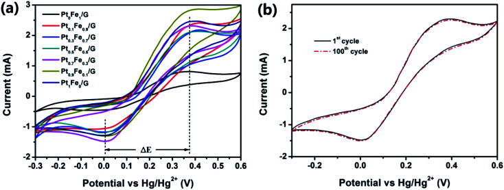
The electrocatalytic properties of the CEs with respect to I3− ions in I−/I3− redox couple was evaluated by cyclic voltammograms (CV), electrochemical impedance spectroscopy (EIS) and Tafel polarization studies. Fig. 3 shows the CV curves of the prepared Pt0Fe1/G, Pt0.1Fe0.9/G, Pt0.3Fe0.7/G, Pt0.5Fe0.5/G, Pt0.7Fe0.3/G, Pt0.9Fe0.1/G, and Pt1Fe0/G CEs. To probe the electrocatalytic activities of various CEs, the reduction current (Jred) and peak-to-peak separation (ΔE) of each CV plot were estimated. The |Jred| and ΔE values are listed in Table 1. We can see that |Jred| increases when the volume ratio of the Pt to Fe precursor decreases from 0 : 1 to 0.7 : 0.3 and that it decreases when the volume ratio of Pt to Fe decreases from 0.7 : 0.3 to 1 : 0. The Pt0.7Fe0.3/G CE exhibits the highest |Jred| value, indicating a higher charge transfer (redox reaction) rate across the |Jred| CE compared to those of other electrodes. These results reveal that the highest |Jred| value was achieved for Pt0.7Fe0.3/G CE. The stability of the Pt0.7Fe0.3/G electrode was further revealed by continuous CV measurements over 100 cycles (Fig. 3b). A slight change in curve shape and no change in Jred and Joxd values can be observed in Pt0.7Fe0.3/G CE even after 100 cycles of scan, and this suggests that the CEs are very stable in I3−/I− electrolyte. The obtained results indicate the good electrochemical stability of Pt0.7Fe0.3/G CE in I−/I3− electrolyte. As presented in Table 1, ΔE is followed the sequence of Pt0Fe1/G (430 mV) > Pt0.1Fe0.9/G (417 mV) > Pt0.3Fe0.7/G (416 mV) > Pt0.5Fe0.5/G (412 mV) > Pt0.7Fe0.3/G (373 mV) > Pt0.9Fe0.1/G (389 mV) > Pt1Fe0/G (402 mV). ΔE of 373 mV for Pt0.7Fe0.3/G was the lowest value among all CEs which indicates the highest rate of the redox reaction of I3−/I−.39,40
Fig. 3. (a) CV plots of electrodes and (b) CV curves of the Pt0.7Fe0.3/G measured with 100 cycles.
Properties of PtxFe1−x/G CEs extracted from the CV, EIS and Tafel measurementsa.
| Counter electrode | |Jred| (mA) | ΔE (mV) | R h (Ω) | R trns (Ω) | R ct (Ω) | J 0 (mA) | J 0 b (mA) | J lim (mA) |
|---|---|---|---|---|---|---|---|---|
| Pt0Fe1/G | 0.460 | 430 | 5.84 | 0.58 | 15.6 | 2.05 | 1.20 | 12.11 |
| Pt0.1Fe0.9/G | 1.077 | 417 | 5.69 | 0.27 | 8.22 | 3.90 | 2.40 | 14.06 |
| Pt0.3Fe0.7/G | 1.169 | 416 | 5.62 | 0.24 | 4.67 | 6.87 | 2.98 | 17.02 |
| Pt0.5Fe0.5/G | 1.201 | 412 | 5.57 | 0.17 | 4.02 | 7.98 | 4.73 | 19.41 |
| Pt0.7Fe0.3/G | 1.479 | 373 | 5.48 | 0.12 | 2.86 | 11.22 | 7.46 | 25.58 |
| Pt0.9Fe0.1/G | 1.301 | 389 | 5.73 | 0.61 | 4.13 | 7.77 | 5.71 | 23.33 |
| Pt1Fe0/G | 1.283 | 402 | 5.82 | 0.83 | 3.95 | 8.12 | 5.14 | 21.73 |
J red: peak current density of the reduction, ΔE: peak-to-peak separation.
The data were calculated from the Tafel curves in Fig. 5.
3.3. Electrochemical impedance spectroscopy measurements
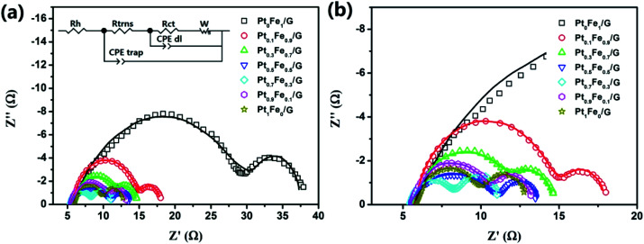
We conducted the EIS analysis to investigate the interfacial charge transfer process of the CEs and the influence of the electrochemical characteristics on the device performance. Nyquist plots obtained from various symmetrical dummy cell fabricated with sandwich-like structure (CE/electrolyte/CE) are presented in Fig. 4. The equivalent circuit is shown in the inset of Fig. 4a, and it is obtained by fitting the Nyquist plots with Z-View software, and the fit parameters (Rh, Rtrns and Rct values) are summarized in Table 1. Both ohmic internal resistance (Rh) and charge transfer resistance (Rct) decrease with increasing the volume ratio of the Pt to Fe precursor from 0 : 1 to 0.7 : 0.3. However, further increase of the volume percentage of Pt precursor led to increase in the Rct value. The Rct value of the Pt0.7Fe0.3/G CE (2.86 Ω) was the smallest among those recorded for other CEs. The relationship between the exchange current density (J0) and Rct is J0 = RT/nFRct, where R is the gas constant, T is the temperature, n is the number of electrons involved in the reduction of the iodide electrolyte, and F is Faraday's constant. The resulting J0 values are shown in Table 1. It is worth noting that a high J0 value indicates a high fill factor (FF) and a high short-circuit current density (Jsc) in the DSSC.41
Fig. 4. (a and b) Nyquist plots of the symmetrical cells fabricated with two identical CEs. The inset shows the equivalent circuit model for fitting.
Considering that the parameter Rtrns is inversely proportional to electrode conductivity,42 we can conclude that the conductivity of Pt1Fe0/G CE is significantly lower compared with that of other PtxFe1−x/G. This phenomenon can be attributed to the synergistic effect of G with the deposited PtFe alloy nanoparticles as well as the synergistic effect of degree of alloying Fe with Pt. The results also indicate that the synergistic effect of G nanosheets with Pt0Fe1 nanoparticles was higher than that of G nanosheets with Pt1Fe0. That is to say, the PtFe alloy/G facilitates electron transfer. In addition, it is shown that Rtrns value of Pt0.7Fe0.3/G was the smallest among all PtxFe1−x/G CEs (Table 1), indicating the highest electrical conductivity of Pt0.7Fe0.3/G CE.
3.4. Tafel measurements
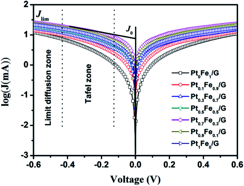
In order to further investigate the synergistic effect and electrocatalytic activity, Tafel measurements were performed. From the corresponding Tafel zone and diffusion zone, we can get the exchange current density (J0) and the limiting diffusion current density (Jlim), respectively. The results are presented in Fig. 5 and Table 1. In theory, J0 is directly related to the electrocatalytic ability of the CE and can be generated from the intersection of the cathodic branch and the equilibrium potential line.43 It was found that the trend of the variation in the J0 values are in the order of Pt0.7Fe0.3/G > Pt0.9Fe0.1/G > Pt1Fe0/G > Pt0.5Fe0.5/G > Pt0.3Fe0.7/G > Pt0.1Fe0.9/G > Pt0Fe1/G, indicating that the electrocatalytic ability of Pt0.7Fe0.3/G CE is better than that of other five CEs. Clearly, the J0 values deduced from Tafel plots follow the same trend, as we observed in EIS analysis. The intersection of the cathodic branch with the Y-axis can be considered as the Jlim. It should be noted that Jlim has a positive relationship with diffusion coefficient (D) and can be expressed as D = lJlim/2nFC, where l and C denote the spacer thickness and electrolyte concentration, respectively. Thus, a larger Jlim value indicates a higher diffusion rate for the I−/I3− redox couple in the electrolyte.44 The highest Jlim value was found for the Pt0.7Fe0.3/G electrode, which indicates a higher diffusion coefficient for the redox couple in the electrolyte. Both EIS and Tafel studies support the relatively high efficiency of the Pt0.7Fe0.3/G CE based DSSC, as it is demonstrated below.
Fig. 5. Tafel polarization of different dummy cells that are same as those used for the EIS measurements.
According to the above electrochemical analysis, it was found that the electrocatalytic activity and charge-transfer ability of these PtxFe1−x/G CEs have been markedly enhanced in comparison with pristine Pt/G CE. This finding can be explained by the alloying effect of transition metals with Pt.45,46 Furthermore, electrocatalytic activity dependence on Pt/Fe stoichiometric ratio of the PtxFe1−x/G CEs was observed. This can be attributed to the electronic structure changes upon alloying Pt with Fe.11
3.5. Photovoltaic performance
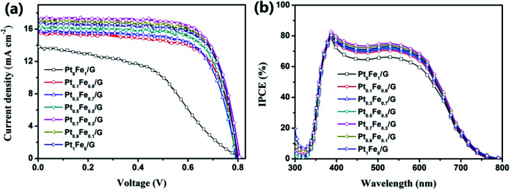
We discuss the effect of CEs on the photovoltaic (PV) performance of DSSCs. The photocurrent–voltage (J–V) characteristics are shown in Fig. 6a and S6,† and the PV parameters are presented in Table 2. We found that the device efficiencies follow the sequence of Pt0.7Fe0.3/G (10.13%) > Pt0.9Fe0.1/G (9.89%) > Pt1Fe0/G (9.72%) > Pt0.5Fe0.5/G (9.30%) > Pt0.3Fe0.7/G (8.75%) > Pt0.1Fe0.9/G (8.62%) > Pt0Fe1/G (5.08%). Note that the DSSC with Pt0.7Fe0.3/G CE yields a remarkable power conversion efficiency of 10.13% (Jsc = 17.29 mA cm−2, Voc = 808 mV, and FF = 72.45%) in comparison to 9.72% for Pt1Fe0/G CE based DSSC. As noted previously, the difference in the Voc values was supported by ΔE.40 It is shown that the FF values ranged from 46.02 to 72.45%, and the trend of the FF value was similar to those of the catalytic activity revealed in the electrochemical measurements (CV, EIS, and Tafel). The low series resistance of a DSSC, which mainly depends on the Rct at the CE/electrolyte interface (evidenced by EIS analysis), can be used to explain this result.47 We see in Table 2 that the Jsc value of the DSSC based on Pt0.7Fe0.3/G CE was found to be the highest value among the DSSCs fabricated from PtxFe1−x/G CEs. The incident photo-current efficiency (IPCE) performance tests were conducted with same electrolyte solution to further confirm the change in Jsc values. The resultant IPCE spectra are presented in Fig. 6b. The IPCE of the Pt0.7Fe0.3 CE based DSSC was higher than that of the other PtxFe1−x/G CE based device over the visible wavelength. Higher the IPCE, greater will be the Jsc value. It was found that the change in the Jsc values is followed the sequence of Pt0.7Fe0.3/G (17.99 mA cm−2) > Pt0.9Fe0.1/G (17.65 mA cm−2) > Pt1Fe0/G (17.12 mA cm−2) > Pt0.5Fe0.5/G (17.05 mA cm−2) > Pt0.3Fe0.7/G (16.14 mA cm−2) > Pt0.1Fe0.9/G (15.61 mA cm−2) > Pt0Fe1/G (13.67 mA cm−2). The obtained results are in good accordance with the change of Jsc in the PV performances. The highest Jsc value of 17.99 mA cm−2 was found in the cell with the Pt0.7Fe0.3/G electrode which is due to the high electrochemical catalytic activity of the CEs. The higher catalytic activity leads to an increase in the reduction rate of I3− to I−, which subsequently diffuse into the working electrode for the ground state recovery of the dye N719. As shown in Fig. S7,† the long-term stability of DSSCs with different PtxFe1−x/G CEs for 20 days was presented. There are only slight decreases in efficiency values, and it indicates that PtxFe1−x/G CE materials can be used as good CE alternatives to traditional Pt electrode for DSSCs. It was revealed that 86.4% of the PEC value is kept for Pt0Fe1/G CE based DSSC in comparison to 92.6%, 95.8%, 96.0%, 95.4%, 94.8% and 89.1% for the devices with Pt0.1Fe0.9/G, Pt0.3Fe0.7/G, Pt0.5Fe0.5/G, Pt0.7Fe0.3/G, Pt0.9Fe0.1/G, and Pt1Fe0/G, respectively. Obviously, pure Pt or pure Fe/G CE based DSSC exhibited relatively weak lower long-term stability. This result can be explained by the research findings of Tang and coworkers.48 In their report, the authors have carefully described the chemical dissolution of alloy CE in a real liquid-junction DSSC device. They pointed out that the competitive reactions of Fe element with I3−/I− can restrict the dissolution of Pt species and therefore protect the high catalytic activity of CEs.
Fig. 6. (a) Current density–voltage curves of DSSCs with different CEs. (b) IPCE curves of different devices.
Photovoltaic properties of DSSCs with PtxFe1−x/G CEs.
| Counter electrode | J sc (mA cm−2) | J sc a (mA cm−2) | V oc (mV) | FF (%) | η (%) |
|---|---|---|---|---|---|
| Pt0Fe1/G | 13.79 | 13.67 | 799 | 46.02 | 5.08 ± 0.20 |
| Pt0.1Fe0.9/G | 15.52 | 15.61 | 802 | 69.25 | 8.62 ± 0.15 |
| Pt0.3Fe0.7/G | 15.83 | 16.14 | 794 | 69.63 | 8.75 ± 0.13 |
| Pt0.5Fe0.5/G | 16.28 | 17.05 | 790 | 72.26 | 9.30 ± 0.19 |
| Pt0.7Fe0.3/G | 17.29 | 17.99 | 808 | 72.45 | 10.13 ± 0.11 |
| Pt0.9Fe0.1/G | 17.13 | 17.65 | 797 | 72.44 | 9.89 ± 0.12 |
| Pt1Fe0/G | 16.77 | 17.12 | 799 | 72.42 | 9.72 ± 0.17 |
The values are obtained from IPCE measurements.
4. Conclusion
In this study, well-dispersed PtxFe1−x nanoparticles were anchored on G by a facile one-step atmospheric plasma reaction method. By controlling the volume ratio of Pt and Fe precursors, the chemical composition of the PtxFe1−x/G can be easily tuned, as confirmed in an XPS analysis. The optimization of the chemical composition of the PtxFe1−x/G nanohybrid resulted in optimizing the catalytic activity toward a reduction of triiodide ions, as reflected by the smallest series resistance values and charge transfer resistance values at the electrolyte/counter electrode interface. In addition, TiO2 nanoparticles/G photoanode material was prepared by atmospheric plasma reaction method. As a result, the DSSCs using Pt0.7Fe0.3/G CE and TiO2 nanoparticles/G photoanode obtained PCE of 10.13% which is higher than Pt1Fe0/G CE (9.72%). The excellent electrocatalytic properties, simple synthesis process, and the low-cost of the Pt0.7Fe0.3/G CE suggest that the Pt0.7Fe0.3/G CE is very promising as a cost-effective stable CEs for efficient and inexpensive DSSCs.
Conflicts of interest
There are no conflicts to declare.
Supplementary Material
Acknowledgments
This work was supported by the Qing Lan Project of Jiangsu Province.
Electronic supplementary information (ESI) available. See DOI: 10.1039/d0ra10067f
References
- Regan B. O. Gratzel M. Nature. 1991;353:737–781. doi: 10.1038/353737a0. [DOI] [Google Scholar]
- Park N. G. J. Electrochem. Sci. Technol. 2010;1:69–74. doi: 10.5229/JECST.2010.1.2.069. [DOI] [Google Scholar]
- Hou Y. Wang D. Yang X. H. Fang W. Q. Zhang B. Wang H. F. Lu G. Z. Hu P. Zhao H. J. Yang H. G. Nat. Commun. 2013;4:1–8. doi: 10.1038/ncomms2547. [DOI] [PubMed] [Google Scholar]
- Papageorgiou N. Coord. Chem. Rev. 2004;248:1421–1446. doi: 10.1016/j.ccr.2004.03.028. [DOI] [Google Scholar]
- Song N. J. Chen C. M. Lu C. Liu Z. Kong Q. Q. Cai R. J. Mater. Chem. A. 2014;2:16563–16568. doi: 10.1039/C4TA02693D. [DOI] [Google Scholar]
- Zhang L. Mulmudi H. K. Batabyal S. K. Lam Y. M. Mhaisalkar S. G. Phys. Chem. Chem. Phys. 2012;14:9906–9911. doi: 10.1039/C2CP40900C. [DOI] [PubMed] [Google Scholar]
- Acharya K. P. Khatri H. Marsillac S. Ullrich B. Zamkov M. Appl. Phys. Lett. 2010;97:201108. doi: 10.1063/1.3518481. [DOI] [Google Scholar]
- Liu J. Tang Q. He B. J. Power Sources. 2014;268:56–62. doi: 10.1016/j.jpowsour.2014.06.022. [DOI] [Google Scholar]
- Liu J. Tang Q. He B. Yu L. J. Power Sources. 2015;282:79–86. doi: 10.1016/j.jpowsour.2015.02.045. [DOI] [Google Scholar]
- Zhou Y. Neyerlin R. Olson R. S. Pylypenko R. Bult R. Dinh R. N. Gennett R. Shao R. O'Hayre R. Energy Environ. Sci. 2010;3:1437–1446. doi: 10.1039/C003710A. [DOI] [Google Scholar]
- Dao V. D. Larina L. L. Tran Q. C. Bui V.-T. Nguyen V. T. Pham T. D. Mohamed I. M. A. Barakat N. A. M. Huy B. T. Choi H. S. Carbon. 2017;116:294–302. doi: 10.1016/j.carbon.2017.02.004. [DOI] [Google Scholar]
- Bae K. H. Park E. Dao V. D. Choi H. S. J. Alloys Compd. 2017;702:449–457. doi: 10.1016/j.jallcom.2017.01.252. [DOI] [Google Scholar]
- Dao V.-D. Mater. Today Energy. 2020;16:100384. doi: 10.1016/j.mtener.2020.100384. [DOI] [Google Scholar]
- Dao V. D. Tran Q. C. Ko S. H. Choi H. S. J. Mater. Chem. 2013;1:4436. doi: 10.1039/C3TA10319F. [DOI] [Google Scholar]
- Morishita T. Ueno T. Panomsuwan G. Hieda J. Yoshida A. Bratescu M. A. Saito N. Sci. Rep. 2016;6:36880. doi: 10.1038/srep36880. [DOI] [PMC free article] [PubMed] [Google Scholar]
- Hu X. Shen X. Takai O. Saito N. J. Alloys Compd. 2013;552:351–355. doi: 10.1016/j.jallcom.2012.08.033. [DOI] [Google Scholar]
- Fuldner S. Mild R. Siegmund H. I. Schroeder J. A. Gruber M. Konig B. Green Chem. 2010;12:400–406. doi: 10.1039/B918140G. [DOI] [Google Scholar]
- Ghavre M. Byrne O. Altes L. Surolia P. K. Spulak M. Quilty B. Thampi K. R. Gathergood N. Green Chem. 2014;16:2252–2265. doi: 10.1039/C3GC42393J. [DOI] [Google Scholar]
- Yella A. Lee H. W. Tsao H. N. Yi C. Y. Chandiran A. K. Nazeeruddin M. K. Diau E. W.-G. Yeh C.-Y. Zakeeruddin S. M. Grätzel M. Science. 2011;334:629–634. doi: 10.1126/science.1209688. [DOI] [PubMed] [Google Scholar]
- Gratzel M. Chem. Lett. 2005;34:8–13. doi: 10.1246/cl.2005.8. [DOI] [Google Scholar]
- Chen C.-Y. Wang M. Li J.-Y. Pootrakulchote N. Alibabaei L. Ngoc-Le C.-H. Decoppet J.-D. Tsai J.-H. Grätzel C. Wu C.-G. Zakeeruddin S. M. Gratzel M. ACS Nano. 2009;3:3103–3109. doi: 10.1021/nn900756s. [DOI] [PubMed] [Google Scholar]
- Yuan Z. M. Yin L. W. Nanoscale. 2014;6:13135–13144. doi: 10.1039/C4NR04262J. [DOI] [PubMed] [Google Scholar]
- Pomoni K. Sofianou M. V. Georgakopoulos T. Boukos N. Trapalis C. J. Alloys Compd. 2013;548:194–200. doi: 10.1016/j.jallcom.2012.08.136. [DOI] [Google Scholar]
- Guo E. Y. Yin L. W. J. Mater. Chem. A. 2015;3:13390–13401. doi: 10.1039/C5TA02556G. [DOI] [Google Scholar]
- Guo E. Y. Yin L. W. Zhang L. Y. CrystEngComm. 2014;16:3403–3413. doi: 10.1039/C4CE00019F. [DOI] [Google Scholar]
- Palomares E. Clifford J. N. Haque S. A. Lutza T. Durrant J. R. Chem. Commun. 2002;14:1464–1465. doi: 10.1039/B202515A. [DOI] [PubMed] [Google Scholar]
- Tang Y. B. Lee C. S. Xu J. Liu Z. T. Chen Z. H. He Z. Cao Y.-L. Yuan G. Song H. Chen L. Luo L. Cheng H.-M. Zhang W.-J. Bello I. Lee S.-T. ACS Nano. 2010;4:3482–3488. doi: 10.1021/nn100449w. [DOI] [PubMed] [Google Scholar]
- Chong S. W. Lai C. W. Hamid S. B. A. Materials. 2016;9:1–13. doi: 10.3390/ma9020069. [DOI] [Google Scholar]
- Ma H. Tian J. Cui L. Liu Y. Shan Z. J. Mater. Chem. A. 2015;3:8890–8895. doi: 10.1039/C5TA00527B. [DOI] [Google Scholar]
- Ko H. S. Han H. J. Na G. Lee A. R. Yun J. J. Han E. M. Mol. Cryst. Liq. Cryst. 2013;579:83–88. doi: 10.1080/15421406.2013.802958. [DOI] [Google Scholar]
- Low F. W. Lai C. W. Hamid S. B. A. J. Mater. Sci.: Mater. Electron. 2017;28:3819–3836. doi: 10.1007/s10854-016-5993-0. [DOI] [Google Scholar]
- Merazga A. Al-Zahrani J. Al-Baradi A. Omer B. Badawi A. Al-Omairy S. Mater. Sci. Eng., B. 2020;259:114581. doi: 10.1016/j.mseb.2020.114581. [DOI] [Google Scholar]
- Sun S. Murray C. B. Weller D. Folks L. Moser A. Science. 2000;87:1989–1992. doi: 10.1126/science.287.5460.1989. [DOI] [PubMed] [Google Scholar]
- Nan C. Zhan L. Liao H. Song M. K. Li Y. Cairns E. J. J. Am. Chem. Soc. 2014;136:4659–4663. doi: 10.1021/ja412943h. [DOI] [PubMed] [Google Scholar]
- Canava B. Vigneron J. Etcheberry A. Guillemoles J. F. Lincot D. Appl. Surf. Sci. 2002;202:8–14. doi: 10.1016/S0169-4332(02)00186-1. [DOI] [Google Scholar]
- Rodriguez J. A. Goodman D. W. Science. 1992;257:897–903. doi: 10.1126/science.257.5072.897. [DOI] [PubMed] [Google Scholar]
- Wang P. Zong L. Guan Z. Li Q. Yang J. Nanoscale Res. Lett. 2018;13:33. doi: 10.1186/s11671-018-2448-y. [DOI] [PMC free article] [PubMed] [Google Scholar]
- Yang B. Zhang F. Chen J. Yang S. Xia X. Pullerits T. Deng W. Han K. Adv. Mater. 2017;29:1703758. doi: 10.1002/adma.201703758. [DOI] [PubMed] [Google Scholar]
- Tributsch H. Coord. Chem. Rev. 2004;248:1511–1530. doi: 10.1016/j.ccr.2004.05.030. [DOI] [Google Scholar]
- Dao V. D. Kim S. H. Choi H. S. Kim J. H. Park H. O. Lee J. K. J. Phys. Chem. C. 2011;115:25529–25534. doi: 10.1021/jp208295b. [DOI] [Google Scholar]
- Hod I. González-Pedro V. Tachan Z. Fabregat-Santiago F. Mora-Seró I. Bisquert J. Zaban A. J. Phys. Chem. Lett. 2011;2:3032–3035. doi: 10.1021/jz201417f. [DOI] [Google Scholar]
- Kwon W. Kim J. M. Rhee S. W. Electrochim. Acta. 2012;68:110–113. doi: 10.1016/j.electacta.2012.02.056. [DOI] [Google Scholar]
- Wang W. Pan X. Liu W. Zhang B. Chen H. Fang X. Yao J. Dai S. Chem. Commun. 2014;50:2618–2620. doi: 10.1039/C3CC49175G. [DOI] [PubMed] [Google Scholar]
- Yun S. Wu M. Wang Y. Shi J. Lin X. Hagfeldt A. Ma T. ChemSusChem. 2013;6:411–416. doi: 10.1002/cssc.201200845. [DOI] [PubMed] [Google Scholar]
- Park H. Y. Lim D. H. Yoo S. J. Kim H. J. Henkensmeier D. Kim J. Y. Ham H. C. Jang J. H. Sci. Rep. 2017;7:1–9. doi: 10.1038/s41598-016-0028-x. [DOI] [PMC free article] [PubMed] [Google Scholar]
- Zhang J. Ma M. Tang Q. Yu L. J. Power Sources. 2016;303:243–249. doi: 10.1016/j.jpowsour.2015.11.012. [DOI] [Google Scholar]
- Han L. Koide N. Chiba Y. Islam A. Komiya R. Fuke N. Fukui A. Yamanaka R. Appl. Phys. Lett. 2005;86:737. [Google Scholar]
- Tang Q. Zhang H. Meng Y. He B. Yu L. Angew. Chem., Int. Ed. 2015;54:11448–11452. doi: 10.1002/anie.201505339. [DOI] [PubMed] [Google Scholar]
Associated Data
This section collects any data citations, data availability statements, or supplementary materials included in this article.


