Abstract
Density Functional Theory (DFT) and Grand Canonical Monte Carlo (GCMC) calculations are performed to study the structures and carbon dioxide (CO2) adsorption properties of the newly designed metal–organic framework based on the CAU-8 (CAU stands for Christian-Albrechts Universität) prototype. In the new MOFs, the 4,4′-benzophenonedicarboxylic acid (H2BPDC) linker of CAU-8 is substituted by 4,4′-oxalylbis(azanediyl)dibenzoic acid (H2ODA) and 4,4′-teraphthaloylbis(azanediyl)dibenzoic acid (H2TDA) containing amide groups (–CO–NH- motif). Furthermore, MgO6 octahedral chains where dimethyl sulfoxide (DMSO) decorating the axial position bridged two Mg2+ ions are considered. The formation energies indicate that modified CAU-8 is thermodynamically stable. The reaction mechanisms between the metal clusters and the linkers to form the materials are also proposed. GCMC calculations show that CO2 adsorptions and selectivities of Al-based MOFs are better than those of Mg-based MOFs, which is due to DMSO. Amide groups made CO2 molecules more intensively distributed besides organic linkers. CO2 uptakes and selectivities of MOFs containing H2TDA linkers are better in comparison with those of MOFs containing H2BPDC linkers or H2ODA linkers.
Density Functional Theory (DFT) and Grand Canonical Monte Carlo (GCMC) calculations are performed to study the structures and CO2 adsorption properties of the newly designed metal–organic framework based on the CAU-8 prototype.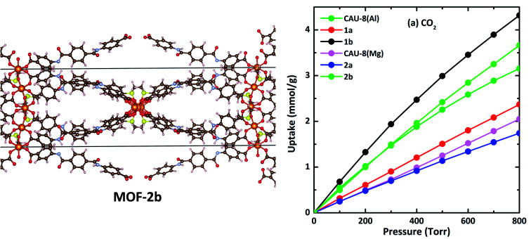
I. Introduction
Metal–organic frameworks (MOFs) are synthesized by self-assembling of metal clusters and organic linkers.1 MOFs are a new class of microporous and mesoporous materials that have attracted much attention for various applications, such as gas storage and separations, catalysis, proton transfer, and drug delivery.2–11 They can be easily self-assembled from simple metal salts and organic linkers. The richness of both inorganic and organic components for the construction of MOFs has provided us tremendous opportunities to synthesize a large number of MOF materials whose pore sizes, pore surface functions, and pore volumes can be systematically tailored to the above-mentioned specific applications.
Carbon dioxide (CO2) storage in MOFs is under intensive research and is used industrially to prepare many intermediate or fine chemicals. Additionally, the selective capture of CO2 from flue gas and natural gas has become the most urgent issue due to climate change concerns.12 Among the reported MOFs for CO2 adsorption and selectivity applications, MOF-74 and MIL-53 are the most well-known, for both materials, the 3D structures are formed from chains running parallel to each other, which results in their potentials for resistance to interpenetration and isoreticular expansion.13–15 MOF-74 is constructed from infinite chains [MII3O3(CO2)3]∝ whereas M is metal with II valence such as Mg, Zn, Fe, … and 2,5-dioxido-1,4-benzenedicarboxylic acid (H4DOBDC).16 MOF-74 is characteristic of the highest density of open metal sites on the 1D channel pore surfaces with a diameter of about 11 Å. The high CO2 adsorption ability of MOF-74 is due to the strong Lewis acid and base interactions between metal ions and oxygen atom of CO2, as well as carbon atom of CO2 with oxygen atoms in organic linkers.17 Among MOF-74, MOF-74(Mg) has a surface area of 1495 m2 g−1 and exceptional CO2 uptake with one of the highest known ambient temperature (25 °C) capacities (∼5 mmol g−1 at 0.1 bar to ∼8 mmol g−1 at 1 bar CO2).18 The remarkable CO2 storage of MOF-74(Mg) may be due to the increased ionic character of the Mg–O bond.18 The post-synthetic functionalization of MOF-74(Mg) with tetraethylenepentamine (TEPA) resulted in a CO2 adsorption performance as high as 26.9 wt% versus 23.4 wt% for the original MOF due to the extra binding sites provided by the multiunit amines.19 Analogous expansion series to MOF-74(Mg) have been synthesized such as MOF-184(Mg) (pore diameter of 20 Å, surface area of 4050 m2 g−1), [Mg2(olsalazine)] (pore diameter of 23.3 Å, surface area of 2331 m2 g−1), … however, CO2 uptake in MOF-184(Mg) and [Mg2(olsalazine)] are 3.04 mmol g−1 and 5 mmol g−1 at 25 °C and 1 bar, respectively, lower than those in the original MOF due to the decrease in the number of metal centers on a unit cell.20,21 MIL-53 consists of infinity chains [MIII2(OH)2(CO2)4]∝ whereas M is metal with III valence such as Al, Cr, Fe, … and benzene-1,4-dicarboxylate terephthalate acid (H2BDC).22 These materials have structural flexibility, also known as “breathing behavior” that leads to a transition between a narrow-pore and a large-pore structure – whose unit cell volume can change up to 40%.23 MIL-53 is capable of adsorption of nearly 40 wt% for CO2.24 MIL-53 has been used for separating CO2 from methane (CH4) thanks to the strong interaction between CO2 molecules with the hydrogen of the corner-sharing hydroxyl groups in the MIL-53.25 Among MIL-53, MIL-53(Al) is extremely stable at high temperatures (up to 773 K), which is an uncommon property compared with its analogues.26 Because of breathing behavior, replacing the BDC linker with longer linkers produced non-porous materials such as MIL-69 or PCN-72.27,28
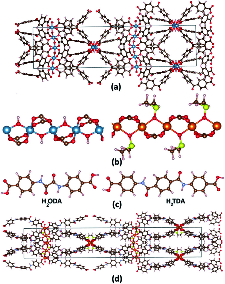
Recently, Reinsch et al. synthesized CAU-8(Al) (CAU stands for Christian-Albrechts Universität) formulated as [Al(OH)(BPDC)] (BPDC: 4,4′-benzophenone dicarboxylate) whose structure is established by [Al2(OH)2(CO2)4]∝ chains connected by V-shape BPDC ligands as shown in Fig. 1a.29 CAU-8(Al) adopts the similar infinity chains with MIL-53(Al), but these chains running perpendicular to each other. Since there are no studies on CO2 storage and selectivity capacity on CAU-8(Al); this stimulates us to choose it as the object for this paper. Recently, several MOFs have been constructed with amide (–CO–NH-) decorated ligands, showing high CO2 adsorption capacities due to these functional groups.30,31 We, therefore, consider a strategy to enhance the CO2 storage and selectivity of CAU-8(Al) by optimizing the organic linker by anchoring this polar functional group. We select two organic linkers: 4,4′-(oxalylbis(azanediyl)dibenzoic acid (H2ODA) and 4,4′-teraphthaloylbis(azanediyl))dibenzoic acid (H2TDA) (Fig. 1c). We consider these linkers with two groups of –CO–NH- but different lengths to study the effect of linker length on the surface area as well as the ability to absorb and select CO2 of the material. In addition, the linker in the CAU-8 has a V-shape whereas numerous porous MOFs are constructed from linear organic linkers in previously reported literature,9,32 we have used linear linkers in this study. The 1a and 1b structures are formed from CAU-8(Al) by replacing the H2BPDC linker with H2ODA and H2TDA linkers, respectively.
Fig. 1. (a) CAU-8(Al) structure. (b) [Al2(OH)2(CO2)4]∝ cluster and {Mg2[OS(CH3)2]2(CO2)4}∝ cluster, (c) 4-(4-carboxybenzamido)benzoic acid (H2ODA) and 4,4′-(terephthaloylbis(azanediyl))dibenzoic acid (H2TDA) linkers. (d) 2b structure. Atom color: Al, blue; Mg, orange; C, brown; N, pale blue; O, red; H, pale pink; S, yellow.
In 2013, Zhou et al. synthesized PCN-72 which is comprised of {Mg2[OS(CH3)2]2(CO2)4}∝ cluster and TTTP ligand (2′,3′,5′,6′-tetramethyl-[1,1′:4′,1′′-terphenyl]4,4′′-dicarboxylate) and whose topology is similar to MIL-53.28 The structure of {Mg2[OS(CH3)2]2(CO2)4}∝ cluster is similar to [Al2(OH)2(CO2)4]∝ but axial position bridged two metal ions –OH is replaced by dimethyl sulfoxide OS(CH3)2 (DMSO) (Fig. 1b). PCN-72 is a non-porous material because of its topology and long linear ligand. After removing coordinated DMSO at 360 °C, PCN-72 can selectively adsorb CO2 over N2.28 After that, to our knowledge, no more MOFs have been synthesized from this cluster. Therefore, the effect of this cluster on CO2 absorption and selectivity has not been studied. We have successfully designed CAU-8(Mg) by replacing Al with Mg cluster, thus, the CO2 adsorption and selectivity of CAU-8(Mg) are also studied in this work. Similarly, the 2a and 2b structures are formed from CAU-8(Mg) by replacing the H2BPDC linker with H2ODA and H2TDA linkers, accordingly. The structure of 2b is displayed in Fig. 1d.
In the present work, Density Functional Theory (DFT) is accessed to accurately describe the structure of six MOFs. The formation energies are also scrutinized to determine whether they can be synthesized successfully. The reaction mechanisms between compounds to synthesize these materials are examined for the first time by Gaussian. Finally, the effects of axial molecules and linker lengths on CO2 absorption and selectivity of these MOFs by Grand Canonical Monte Carlo (GCMC) are evaluated.
II. Calculation method
Structural modeling of new MOFs is carried out in the Materials Studio package (Accelrys Inc.). The theoretical models are optimized by the Forcite module using the Universal Force Field (UFF).33 The quality of the geometry optimization in Forcite is set to fine. The geometry optimization algorithm is a smart algorithm which is a cascade of the steepest descent and quasi Newton methods. This is done using an iterative process of steepest descent in which the atomic coordinates and the cell parameters are adjusted until the total energy of the structure is minimized. These models are then used as initial structures for the full geometry optimization under periodic boundary conditions within the Vienna Ab Initio Simulation Package (VASP).34,35 The generalized gradient approximation (GGA) functional and projector-augmented wave (PAW) method are employed.36,37 The ion–electron interactions are described by Perdew, Burke, and Ernzerhof (PBE) exchange-correlation.38 The variant of dispersion corrected developed by Grimme et al. PBE-D3(BJ) is adopted.39 The periodic DFT optimizations are done using primitive cells for a reduction in the research expense and time (about 248–440 atoms per primitive cell). The 2 × 2 × 2 k-point optimizations are performed with an energy cut-off of 550 eV. The energy and force convergence criteria are set to 10−5 eV and −0.01 eV Å−1, respectively. Brillouin-zone integration is performed with a Gaussian broadening of 0.1 eV during all relaxations. In this paper, the PAW treatment of pseudopotentials uses the 3s electrons for Mg; 3s and 3p electrons for Al, S; 2s and 2p electrons for N, C, O, and 1s electron for H. All crystal structures are visualized using the VESTA program.40
The formation energy is the difference between the total energies of products and the total energies of the reactants, whereas the total energies of reactants obtained after optimizing them in a box of length 25 Å by VASP.
Various guest gas molecules are introduced to various locations of the channel pore, followed by a full structural relaxation. To obtain the gas binding energy, an isolated gas molecule placed in a supercell (with the same cell dimensions as the MOF crystal) is also relaxed as a reference. The static binding energy (at T = 0 K) is then calculated using:
| Eb = EMOF_gas − EMOF − Egas | 1 |
where, EMOF_gas, EMOF, Egas refer to the total energy of the MOFs with one gas molecule, the system, and an isolated gas molecule, respectively. A negative value of Eb corresponds to energetically stable adsorption.
The accessible surface areas of MOFs are calculated using the atom volume and surface module in Materials Studio with the solvent radius set to 1.82 Å (kinetic radius of N2). Pore volumes are estimated using helium as the probing atom at 298 K and 1 bar in RASPA.
To investigate the reaction mechanism, the localized atomic-orbital-basis calculation method is employed. The geometries of all stationary points are fully optimized, without symmetry constraints, employing Perdew–Burke–Ernzerhof (PBE) functional38 implemented in the Gaussian16 program. The 6-311g** basis set is employed to construct the electronic wave-functions for all elements. The D3(BJ) correction is introduced to account for long-range van der Waals interactions.39 The Quadratic Synchronous Transit (QST) approach is used to predict transition states.41 QST3 with three molecule specifications (a reactant, a product, and a guess transition state) can be used to computationally locate a transition state. The stability of the obtained structures is confirmed by vibration analysis.
The Grand Canonical ensemble Monte Carlo (GCMC) simulations performed using the RASPA 2.0 (molecular simulation software for adsorption and diffusion in flexible nanoporous materials) to determine the adsorbed number of gas molecules in MOFs.42,43 The interactions of gas molecules with the MOFs are modeled using Lennard-Jones (LJ) 12–6 and Coulomb potentials. LJ parameters are taken from TraPPE-UA for MOFs (Table S2, ESI†),44–50 which has been successfully applied in prediction adsorption in Al-MOFs.51,52 Moreover, as in the case of MIL-53(Al), the LJ contributions from the Al atoms of Al-MOFs in this paper are not considered since Al atoms are shielded by the surrounding O atoms and the polarizability of Al atoms is much lower than those of O atoms.49 This approach is applied successfully in MIL-68(Al) and MIL-91(Al).53,54 The attractive vdW force exerted by the Mg atoms is not considered following the same criteria. For the van der Waals terms, the atom-based summation method is used with the cubic spline truncation. 12.0 Å is used as a cut-off radius for van der Waals terms. Ewald summation method with 10−4 kJ mol−1 accuracy is used to calculate electrostatic interactions. The atomic charges of MOFs are estimated using electrostatic potentials using a grid-based method (ChelpG)55 (Table S3, ESI†), that has been widely used to predict isotherms of various guests in Al-MOFs.53,56
Simulations are performed with trial configurations consist of 5 × 10⁵ cycles for the equilibration and 105 cycles for the production step. For each cycle, Monte Carlo (MC) moves include attempts to insert, delete, exchange, rotate, translate, or recycle an adsorbed molecule. The probability of each type of move is equal in the simulations. All simulations are performed at a room temperature of 25 °C (298 K). The CO2 molecule is represented by model proposed by Murthy.57 CO2 is modeled as a rigid linear triatomic molecule with three charged Lennard-Jones interaction sites located at each atom with a C O bond length of 1.18 Å. CH4 and N2 are modeled by the united-atom models, in which it is treated as a single interaction center with its efficient potential. The potential parameters of CH4, N2 are obtained from the TraPPE force field58 and ref. 59.
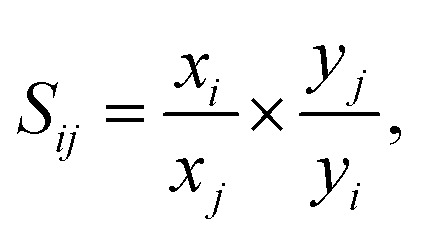
The adsorption selectivities for binary mixtures of CO2/CH4 and CO2/N2 are defined by
 |
2 |
where xi, xj is the mole fraction of component i, j in the adsorbed phase; and yi, yj is the mole fraction of component i, j in the bulk, respectively.
III. Results and discussion
A. Structural optimizations and electronic structures
The structural characteristics of all MOFs are presented in Table 1. The conventional cells of all structures are in the tetragonal crystal system with the I41/a space group (no. 88). The experimental lattice parameters of CAU-8(Al) are a = 13.06 Å, and c = 52.57 Å.29,60 These lattice constants in PBE-D3(BJ) are, respectively, 0.69% and 1.46% smaller than the experimental values. Apparently, the lattice parameters of CAU-8 obtained from the PBE-D3(BJ) method are well consistent with experimental observations. The calculated lattice parameters of CAU-8(Mg) are a = 14.73 Å, and c = 53.13 Å. As replacing the Al cluster with the Mg cluster in the CAU-8 structure, the lattice constant c increased slightly but the lattice constant a increased by 13.57%, resulted in an increase of the volume 32.31%. This is explained by the angle increase made by three sequential metal atoms in metal chains from 165.25° for Al to 174.13° for Mg and bond length between two sequential metal atoms. The Al–Al and Al–O(OH) distances in CAU-8(Al) are 3.27 Å and 1.84 Å while the Mg–Mg, Mg–O(DMSO) distances are about 3.69 Å and 2.21 Å, respectively, in CAU-8(Mg). Such a long-distance suggests that weak interaction can be present between Mg atoms. The lattice parameters of 1a structure are a = 13.31 Å and c = 72.75 Å and for the 1b structure are a = 13.05 Å and c = 85.89 Å which implies that alteration of longer linker makes the length of the c-axis increases significantly. This is similar when comparing lattice parameters between CAU-8(Mg), 2a and 2b. The lattice parameters of 2a structure are a = 14.21 Å and c = 73.07 Å and for the 2b structure are a = 14.11 Å and c = 84.28 Å.
The structural data of new MOFs. The data in brackets is the difference between simulation and experiment. The experimental data are taken from ref. 61 while data in the square bracket are taken from ref. 60.
| MOFs | CAU-8(Al) (experiment) | CAU-8(Al) (simulation) | 1a | 1b | CAU-8(Mg) | 2a | 2b |
|---|---|---|---|---|---|---|---|
| Cluster | [Al2(OH)2(CO2)4]∝ | {Mg2[OS(CH3)2]2(CO2)4}∝ | |||||
| Linker | H2BPDC | H2ODA | H2TDA | H2BPDC | H2ODA | H2TDA | |
| Empirical formula | AlO6C15H9 | AlO7N2C16H11 | AlO7N2C22H15 | MgO6C17H14S | MgO7N2C18H16S | MgO7N2C24H20S | |
| Number of atom/unit cell | 496 | 592 | 752 | 624 | 720 | 880 | |
| Crystal system | Tetragonal | ||||||
| Space group | I41/a (88) | ||||||
| a = b (Å) | 13.06 | 12.97 (−0.69%) | 13.31 | 13.05 | 14.73 | 14.21 | 14.11 |
| c (Å) | 52.57 | 51.80 (−1.46%) | 72.75 | 85.89 | 53.13 | 73.07 | 84.28 |
| V (Å3) | 8969.11 | 8706.37 (−2.93%) | 12 890.76 | 14 627.99 | 11 518.99 | 14 748.51 | 16 780.87 |
| Surface area (m2 g−1) | 1078 [1234] | 1074.74 | 2359.65 | 1629.02 | 1160.69 | 2189.06 | 2029.22 |
| Pore volume (cm3 g−1) | 0.48 [0.54] | 0.49 | 0.80 | 0.68 | 0.58 | 0.74 | 0.69 |
The pore volume and accessible surface area of all MOFs are also listed in Table 1. The experimental surface area and pore volume of CAU-8(Al) in ref. 61 are 1078 m2 g−1 and 0.48 cm3 g−1 while these values are 1234 m2 g−1 and 0.54 cm3 g−1 in ref. 60. The calculated surface area and pore volume of CAU-8(Al) are 1074.74 m2 g−1 and 0.49 cm3 g−1, similar to the reported experimental value from the former reference. It is shown that the surface area and pore volume of CAU-8(Mg) (1160.69 m2 g−1, 0.58 cm3 g−1) is larger than CAU-8(Al). The surface areas of modified MOFs also found that much greater than CAU-8(Al). The surface areas of 1a and 1b are calculated to be 2359.65 and 1629.02 m2 g−1 with pore volumes of 0.80 and 0.68 cm3 g−1, respectively. The surface areas of 2a and 2b are 2189.06 and 2029.22 m2 g−1 while their pore volumes are 0.74 and 0.69 cm3 g−1. The surface areas of these MOFs are similar to NOTT-125 (2447 m2 g−1),62 NJU-Bai-17 (2423 m2 g−1),63 but it is moderate in comparison with PCN-68 (5109 m2 g−1).64 Apparently, the surface area and pore volume of MOFs-containing ODA2− linker greater than those of MOFs-containing TDA2−. Additionally, the surface area and pore volume of MOFs-containing BPDC2− linker are smallest.
B. Formation energy and reaction mechanism
The formation energy provides an excellent means of determining whether theoretically predicted phases are stable. This information can also serve as a guide for evaluating possible synthesis routes. We have calculated the formation energies by VASP based on the chemical reaction equations.
First, H2ODA linker may be synthesized from oxalyl chloride and aminosalicylic acid
| OCl–C2–OCl + 2NH2–C6H4–COOH → H2ODA + 2HCl. | 3 |
H2TDA linker may be formed by the reaction of terephtaloyl chloride and aminosalicylic acid
| OCl–C6H4–OCl + 2NH2–C6H4–COOH → H2TDA + 2HCl. | 4 |
Formation energies for (3) and (4) reactions are −240.80 kJ mol−1 and −154.79 kJ mol−1, accordingly, implying that H2ODA and H2TDA linkers can be successfully synthesized.
The reactions of Al(NO3)3·9H2O and H2L (L = BPDC, ODA or TDA) may yield the CAU-8(Al), 1a, 1b crystal structures
| 8Al(NO3)3·9H2O + 8H2L → Al8L8(OH)8 + 24HNO3 + 64H2O. | 5 |
Formation energies for CAU-8(Al), 1a and 1b are 3210.54, 3346.62 and 3135.20 kJ mol−1, respectively. The reactions of Mg(NO3)2·6H2O and H2L (L = BPDC, ODA or TDA) may yield the CAU-8(Mg), 2a, 2b crystal structures
| 8Mg(NO3)2·6H2O + 8H2L + 8OSC2H6 → Mg8L8(OSC2H6)8 + 16HNO3 + 48H2O. | 6 |
Formation energies for CAU-8(Mg), 2a and 2b are 1595.29 kJ mol−1, 1496.29 kJ mol−1 and 1470.82 kJ mol−1. The results establish unambiguously that eqn (5) and (6) depict endothermic reactions for the Al-based and Mg-based MOFs, which is suitable for solvothermal reaction – used in synthesized CAU-8(Al).
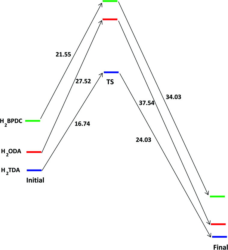
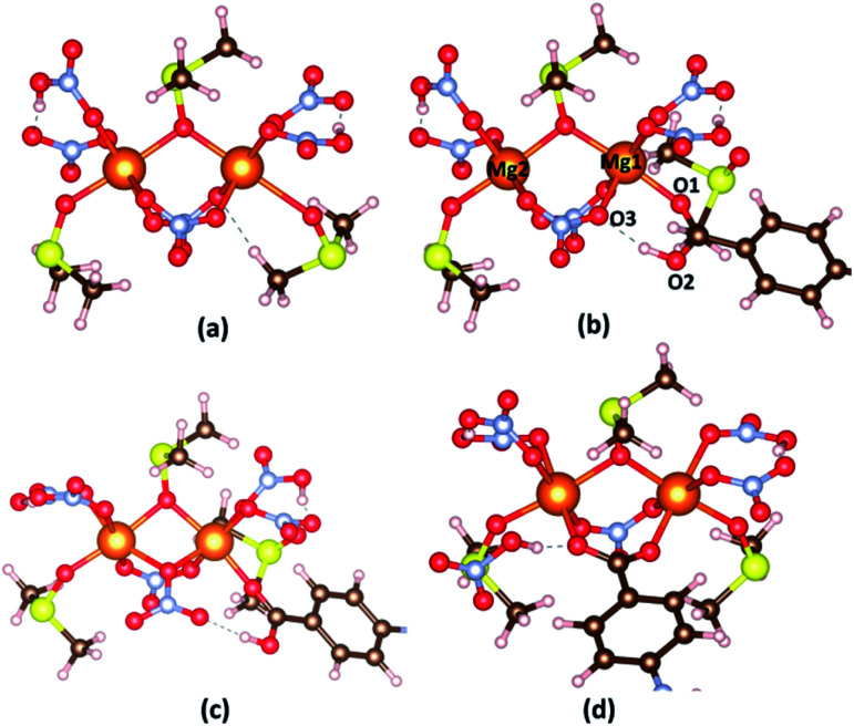
To provide a fundamental understanding of CAU-8(Al), 1a or 1b formation, the reaction mechanisms from metal cluster and organic linkers are considered by Gaussian. The reaction states and the energy profile are shown in Fig. 2 and 3. The Al2(NO3)5(HNO3)(OH)(H2O)2 model cluster shown in Fig. 2a.
Fig. 2. (a) The model cluster; (b) the initial reactant, (c) transition state and (d) final state between Al2(NO3)5(HNO3)(OH)(H2O)2 cluster and H2L linkers (L = BPDC, ODA or TDA). Atom color: Al, blue; C, brown; N, pale blue; O, red; H, pale pink; S, yellow.
Fig. 3. The energy profile of forming the bond between [Al2(OH)2(CO2)4]∝ cluster with H2L (L = BPDC, ODA or TDA) in unit of kJ mol−1.
First, as a linker (H2L) attempts to substitute a NO3−, O1 atom from the linker approaches closely, repel an H2O molecule and make a coordination bond to Al1 cation in the cluster. The binding energy of the Al cluster and linker is defined by
| Eb = EAl_cluster–H2L − EAl_cluster − EH2L. | 7 |
The binding energies of Al cluster with H2BPDC, H2ODA, and H2TDA are −76.15, −84.18, −87.73 kJ mol−1, which shows the favorability of H2TDA. Such Al cluster – H2L complexes are regarded as initial reactant as shown in Fig. 2b. The proton H+ remains to be associated with the linker molecule while attempts to make a weak bond of 1.68 Å with an O3 atom from nearby NO3−. The distance between Al1–O1, Al1–O3, and Al2–O2 are about 1.87 Å, 1.97 Å, 5.85 Å. In those transition states as shown in Fig. 2c, the O3 from NO3− departs from Al1 and starts to links with H atom (from –OH of the linker) to form HNO3, and the distance between Al1–O3 is about 4.30 Å. The linkers move closely toward Al2 whereas the Al2–O2 distance is roughly 4.30 Å. The H2BPDC, H2ODA, H2TDA transition states are found to be 21.44, 27.52, 16.74 kJ mol−1 above the initial reactant. After that, HNO3 residue goes away and the linker is more motivated to attack the second Al site. The final state is when the Al2–O2 bond is completed. HNO3 residue bonds O2 via hydrogen bond of 1.85 Å. The H2BPDC, H2ODA, H2TDA final states are found to be 34.03, 37.54, 26.03 kJ mol−1 under the transition states.
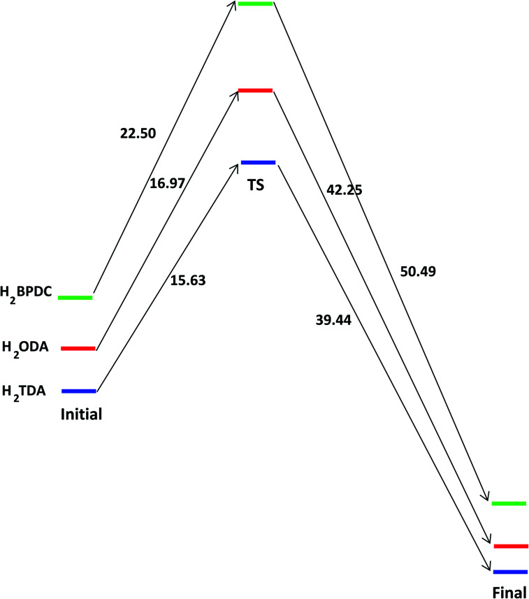
Similarly, the hypothetical states and energy profile of forming the bond between Mg2[OS(CH3)2]3(HNO3)2(NO3)2 cluster with H2L as shown in Fig. 4 and 5. The binding energy of cluster and linker is given by the relation
| Eb = EMgcluster–H2L − EMg_cluster − EH2L. | 8 |
Fig. 4. (a) The model cluster; (b) the initial reactant, (c) transition state and (d) final state between Mg2[OS(CH3)2]3(HNO3)2(NO3)2 cluster and H2L linkers (L = BPDC, ODA or TDA). Atom color: Mg, orange; C, brown; N, pale blue; O, red; H, pale pink; S, yellow.
Fig. 5. The energy profile of forming the bond between {Mg2[OS(CH3)2]2(CO2)4}∝ cluster with H2L (L = BPDC, ODA or TDA) in unit of kJ mol−1.
The binding energies of H2BPDC-cluster, H2ODA-cluster, and (H2TDA)-cluster are −53.76, −55.73, −57.27 kJ mol−1 which shows the slight favorability of H2TDA. At the initial stage, the proton H+ of linker make a weak bond of about 1.70 Å with an O3 atom from nearby NO3−. The distance between Mg1–O1, Mg1–O3, and Mg2–O2 are about 2.05 Å, 2.13 Å, 5.92 Å.
The H2BPDC, H2ODA, H2TDA transition states are found to be 22.50, 16.97, 15.63 kJ mol−1 above the initial reactant. The H2BPDC, H2ODA, H2TDA final states are found to be 50.49, 42.25, 39.44 kJ mol−1 under the transition states.
C. Gas storage and selectivity
In order to verify the reliability of the used force field, simulations of N2 adsorption at 77 K, 298 K, and CH4 at 298 K in CAU-8 are performed to compare against experimental data from the literature as displayed in Fig. 6. Our calculation result of CH4 isotherm at 298 K is basically identical to the experimental results. The calculated N2 isotherm at 77 K and 298 K are underestimated and slightly overestimated with the experimental results from ref. 60. The reason for the deviation is the idealized models used in the simulation, while the actual model is not perfect. This proved that the force field used in this work is able to predict the gas adsorption properties of MOFs with reasonable accuracy.
Fig. 6. The comparison of the simulated and experimental (a) N2 isotherm at 77 K, (b) CH4 at 298 K and (c) CH4 at 298 K in CAU-8(Al).
CH4, N2, and CO2 uptake isotherms of all MOFs are calculated at the temperature of 298 K and the pressure below 800 torr as indicated in Fig. 7. It can be seen that all isotherms are near linear. 1b and 2b show the best CO2 uptake among six MOFs, in particular, the CO2 uptake of 1b and 2b at 298 K and 800 torr are 4.32 mmol g−1 (96.77 cm3 g−1) and 3.66 mmol g−1 (82.08 cm3 g−1), accordingly. The CO2 uptake capacity of 1b is even higher than those of MOFs based on linkers incorporating amide such as HNUST-1 (93.0 cm3 g−1),65 NOTT-125 (92.60 cm3 g−1).62 Meanwhile, the CO2 capacities of CAU-8(Mg) and 2a are the smallest with 2.05 mmol g−1 (45.94 cm3 g−1) and 1.74 mmol g−1 (39.01 cm3 g−1), respectively. The absorbed CO2 amounts of Mg-based MOFs are smaller dramatically compared to Al-based MOFs. These lower gravimetric CO2 capacities of Mg-based MOFs are mainly due to DMSO. Additionally, CO2 adsorption follows the following order: TDA2− > BPDC2− > ODA2− for MOFs containing the same metal cluster.
Fig. 7. (a) CO2, (b) CH4, and (c) N2 isotherms of the new MOFs at 298 K. In all cases, CO2, CH4 and N2 show near–linear isotherms.
By contrast, these MOFs adsorbed very limited amounts of CH4 and N2 under the same conditions. The CH4 and N2 uptakes of 1b are 0.99 mmol g−1 (22.18 cm3 g−1) and 0.28 mmol g−1 (6.19 cm3 g−1) at 298 K and 800 torr, respectively. The CH4 and N2 absorptive capacity of 1b are highest among six MOFs. The higher uptake capacity for CO2 gas over CH4, N2 in these MOFs may be associated with the quadrupole moment of CO2 (−1.34 × 10−39 cm2) which induces efficient interaction with the framework.
Given the increase in the adsorption amounts of these MOFs for CO2 relative to CH4 and N2, we further explore the adsorption selectivity for equimolar CO2–CH4 and CO2–N2 binary mixtures. The highest CO2/CH4 selectivity of 5.65 is available in 1b for the 1 : 1 binary mixtures. Therefore, six MOFs are not suitable for use as adsorbent directly to separate CH4 from CO2. The selectivity of CO2/N2 in 1b reaches 23.87 at 298 K and 800 torr, followed by 2b (20.37). The significant selectivity of Al-based MOFs for CO2 over both N2 can be potentially implemented in the capture of CO2 from landfill gas and natural gas. In both CO2/N2 and CO2/CH4 mixtures, the selectivities of CO2 in MOFs comprising TDA2− ligands are higher than those in their parent MOFs CAU-8(Al) and CAU-8(Mg) while the opposite is true for MOFs comprising ODA2− ligands.
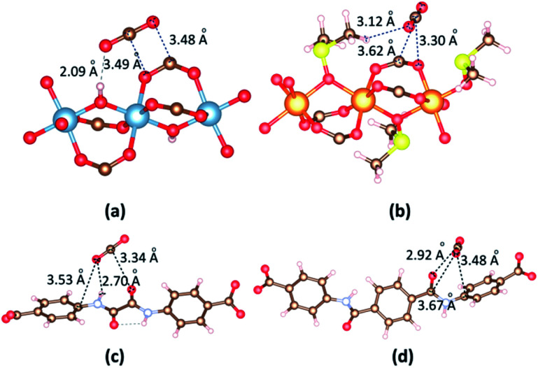
To gain better insight on the CO2 position within the framework and the governing interactions responsible for resultant affinity, we performed the accurate interactions between the metal clusters and CO2 molecules, organic linkers and CO2 molecules. A single CO2 molecule is placed in many different positions in the vicinity of the metal cluster or linker in 1b and 2a with various orientations, and relaxation of the MOF structure and CO2 are made. The most dominant CO2 molecules are identified by VASP as shown in Fig. 8. First, we consider the circumstance that one CO2 molecule close to metal cluster. When CO2 is close to Al cluster, O atoms of CO2 contact with H atom of a hydroxyl and C atom of a carboxyl group of the linker; C atom of CO2 contacts with O atom of a carboxyl group in the linker. The separation of (CO2)O⋯H(OH) is 2.09 Å. The binding energies between CO2 and 1b, 2a are −30.59 kJ mol−1 and −23.50 kJ mol−1, respectively. The significantly lower binding energy and CO2 adsorption capacity found for DMSO-decorated MOFs has confirmed that DMSO molecules hinder CO2 adsorption application.
Fig. 8. The main adsorption sites of CO2 in the vicinity of (a) [Al2(OH)2(CO2)4]∝ cluster, (b) {Mg2[OS(CH3)2]2(CO2)4}∝ cluster, (c) ODA2− linker and (d) TDA2− linker.
In 2a, CO2 is situated on the top of the ODA2− linker wherein not only one O atom forms a –NH⋯O hydrogen bond (H⋯O = 2.70 Å) but also the C atom generates moderate O⋯C (3.34 Å) interaction with the oxalamide group (Fig. 8c). The O atom also contacts with C atom of phenyl ring (3.53 Å). The binding energy between CO2 with ODA2− and TDA2− linkers are −38.27 kJ mol−1 and −38.83 kJ mol−1. This simulation clearly verifies the crucial role of the amide group for high CO2 loading.
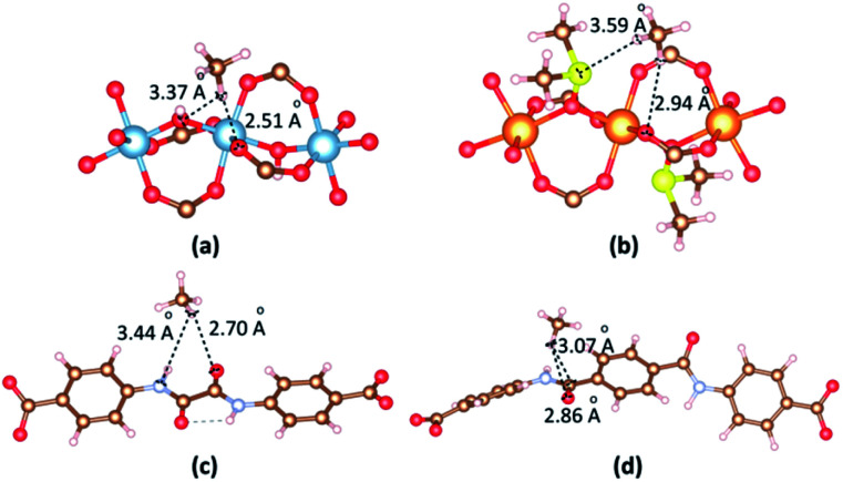
The most dominant CH4 molecules are identified by VASP as shown in Fig. 9. When CO2 is in the vicinity of Al cluster, H atoms of CH4 contact with O atom of hydroxyl and O atom of carboxyl group. The separation of (CH4)H⋯O(carboxyl) is 2.51 Å. When CO2 is in the vicinity of Mg cluster, H atoms of CH4 contact with S atom of DMSO and O atom of carboxyl group. The separation of (CH4)H⋯O(carboxyl) is 2.94 Å. The binding energies between CH4 and 1b, 2a are −23.32 kJ mol−1 and −20.48 kJ mol−1, respectively. When CH4 is close to linkers, H atoms of CH4 contact with O atom of amide groups. The separations of (CH4)H⋯O(amide) are found 2.70 Å and 2.86 Å for 1b and 2a. The binding energies between CH4 and 1b, 2a in the case of CH4 vicinity linkers are −20.51 kJ mol−1 and −17.07 kJ mol−1, respectively.
Fig. 9. The main adsorption sites of CH4 in the vicinity of (a) [Al2(OH)2(CO2)4]∝ cluster, (b) {Mg2[OS(CH3)2]2(CO2)4}∝ cluster, (c) ODA2− linker and (d) TDA2− linker.
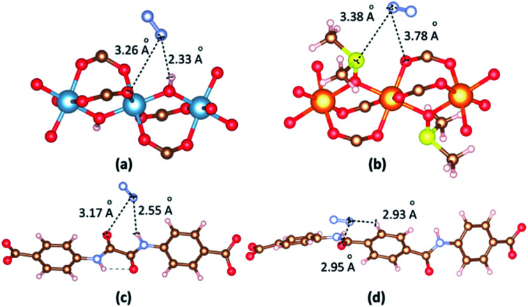
The most dominant N2 molecules are identified by VASP as shown in Fig. 10. When N2 is in the vicinity of the Al cluster, N atoms of N2 contact with O atom of hydroxyl and O atom of a carboxyl group. The separation of (N2)N⋯O(hydroxyl) is 2.33 Å. When N2 is in the vicinity of the Mg cluster, N atoms of N2 contact with S atom of DMSO and O atom of carboxyl group. The separation of (N2)N⋯S(DMSO) is 3.38 Å. The binding energies between N2 and 1b, 2a are −20.26 kJ mol−1 and −19.08 kJ mol−1, respectively. When N2 is close to linkers, H atoms of N2 contact with O and H atom of amide groups. The separations of (N2)N⋯O(amide) are found 3.17 Å and 2.95 Å for 1b and 2a. The binding energies between N2 and 1b, 2a in the case of N2 vicinity linkers are −19.08 kJ mol−1 and −18.42 kJ mol−1, respectively.
Fig. 10. The main adsorption sites of N2 in the vicinity of (a) [Al2(OH)2(CO2)4]∝ cluster, (b) {Mg2[OS(CH3)2]2(CO2)4}∝ cluster, (c) ODA2− linker and (d) TDA2− linker.
IV. Conclusions
In summary, four new MOFs have been constructed by employing 4,4′-(oxalylbis(azanediyl)dibenzoic acid (H2ODA) and 4,4′-teraphthaloylbis(azanediyl))dibenzoic acid (H2TDA) containing amide groups (–CO–NH-) with [Al2(OH2)2(CO2)4]∝ and {Mg2[OS(CH3)2]2(CO2)4}∝ clusters based on CAU-8 prototype. All MOFs exhibit positive formation energies, which are shown they are formed in the endothermic reactions. The proposed reaction mechanisms between Al and Mg clusters with organic linkers are suggested as follows: first, the linker attempts to approach closely and make a coordination bond to one metal cation in the cluster. Then, the proton H+ in the linker molecule attempts to make a bond with an O atom to form nitric acid. Finally, the linker attacks the second metal site and forms the connection between the cluster and the linker. 1b has the highest absorption of CO2 among the materials with 4.32 mmol g−1 at 298 K and 1 atm. The CO2/N2 selectivity of this material is highest (23.87), therefore, it is possible to apply in the capture of CO2 from landfill gas and natural gas. Compared with Al-based MOFs, Mg-based MOFs have lower absorptions and selectivities, which is attributed to the axial positions of DMSO. The utilization of longer linker TDA2− instead of ODA2− in MOFs construction results in materials greater CO2 absorption despite the larger surface area of MOFs-containing ODA2− linker. It has been shown that CO2 tends to bind with the amide group in the linker in the materials.
Conflicts of interest
The authors declare no competing financial interest.
Supplementary Material
Acknowledgments
D. T.-X. D. are thankful for the financial support from Vietnam National University in Ho Chi Minh City under grant C2019-50-01. We are grateful for computational support from the High-Performance Computing Laboratory, Faculty of Computer Science and Engineering, University of Technology, Vietnam National University, and the Institute for Material Research, Tohoku University. D. T.-X. D. expresses gratitude to Dr Hung Minh Le (Washington State University, United States), Dr Phuong Thi-Kieu Nguyen (Duy Tan University, Vietnam), Dr Huong Thi-Diem Nguyen (Ho Chi Minh City University of Science, Vietnam) and Prof. Thang Bach Phan (INOMAR) for their valuable discussions and support in this work. The authors thank two referees for their constructive and valuable suggestions.
Electronic supplementary information (ESI) available. See DOI: 10.1039/d0ra10121d
Notes and references
- Furukawa H. Cordova K. E. O'Keeffe M. Yaghi O. M. Science. 2013;341:1230444. doi: 10.1126/science.1230444. [DOI] [PubMed] [Google Scholar]
- Horcajada P. Serre C. Vallet-Regi M. Sebban M. Taulelle F. Ferey G. Angew. Chem. 2006;45:5974. doi: 10.1002/anie.200601878. [DOI] [PubMed] [Google Scholar]
- Miller S. R. Heurtaux D. Baati T. Horcajada P. Greneche J. M. Serre C. Chem. Commun. 2010;46:4526. doi: 10.1039/C001181A. [DOI] [PubMed] [Google Scholar]
- Doan T. L. H. Nguyen H. L. Pham H. Q. Pham-Tran N.-N. Le T. N. Cordova K. E. Chem.–Asian J. 2015;10:2660. doi: 10.1002/asia.201500641. [DOI] [PubMed] [Google Scholar]
- Nguyen P. T. K. Nguyen H. T. D. Pham H. Q. Kim J. Cordova K. E. Furukawa H. Inorg. Chem. 2015;54:10065. doi: 10.1021/acs.inorgchem.5b01900. [DOI] [PubMed] [Google Scholar]
- Nguyen N. T. T. Furukawa H. Gándara F. Trickett C. A. Jeong H. M. Cordova K. E. Yaghi O. M. J. Am. Chem. Soc. 2015;137:15394. doi: 10.1021/jacs.5b10999. [DOI] [PubMed] [Google Scholar]
- Nguyen B. T. Nguyen H. L. Nguyen T. C. Cordova K. E. Furukawa H. Chem. Mater. 2016;28:6243. doi: 10.1021/acs.chemmater.6b02431. [DOI] [Google Scholar]
- Nguyen L. H. T. Nguyen T. T. Nguyen H. L. Doan T. L. H. Tran P. H. Catal. Sci. Technol. 2017;7:4346. doi: 10.1039/C7CY01668A. [DOI] [Google Scholar]
- Nguyen P. T. K. Nguyen H. T. D. Nguyen H. N. Trickett C. A. Ton Q. T. Gutierrez-Puebla E. Angeles Monge M. Cordova K. E. Gandara F. ACS Appl. Mater. Interfaces. 2018;10:733. doi: 10.1021/acsami.7b16163. [DOI] [PubMed] [Google Scholar]
- Nguyen H. T. D. Tran Y. B. N. Nguyen H. N. Nguyen T. C. Gándara F. Nguyen P. T. K. Inorg. Chem. 2018;57:13772. doi: 10.1021/acs.inorgchem.8b02293. [DOI] [PubMed] [Google Scholar]
- Nguyen M. V. Lo T. H. N. Luu L. C. Nguyen H. T. T. Tu T. N. J. Mater. Chem. A. 2018;6:1816. doi: 10.1039/C7TA10148A. [DOI] [Google Scholar]
- D'Alessandro D. M. Smit B. Long J. R. Angew. Chem., Int. Ed. 2010;49:6058. doi: 10.1002/anie.201000431. [DOI] [PubMed] [Google Scholar]
- Rosi N. L. Eddaoudi M. Kim J. O'Keeffe M. Yaghi O. M. Angew. Chem., Int. Ed. 2002;41:284. doi: 10.1002/1521-3773(20020118)41:2<284::AID-ANIE284>3.0.CO;2-M. [DOI] [PubMed] [Google Scholar]
- Horike S. Shimomura S. Kitagawa S. Nat. Chem. 2009;1:695. doi: 10.1038/nchem.444. [DOI] [PubMed] [Google Scholar]
- Horcajada P. Salles F. Wuttke S. Devic T. Heurtaux D. Maurin G. Vimont A. Daturi M. David O. Magnier E. Stock N. Filinchuk Y. Popov D. Riekel C. Ferey G. Serre C. J. Am. Chem. Soc. 2011;133:17839. doi: 10.1021/ja206936e. [DOI] [PubMed] [Google Scholar]
- Deng H. Grunder S. Cordova K. E. Valente C. Furukawa H. Hmadeh M. Gándara F. Whalley A. C. Liu Z. Asahina S. Kazumori H. O'Keeffe M. Terasaki O. Stoddart J. F. Yaghi O. M. Science. 2012;336:1018. doi: 10.1126/science.1220131. [DOI] [PubMed] [Google Scholar]
- Hou X.-J. He P. Li H. Wang X. J. Phys. Chem. C. 2013;117:2824. doi: 10.1021/jp310517r. [DOI] [Google Scholar]
- Caskey S. R. Wong-Foy A. G. Matzger A. J. J. Am. Chem. Soc. 2008;130:10870. doi: 10.1021/ja8036096. [DOI] [PubMed] [Google Scholar]
- Su X. Bromberg L. Martis V. Simeon F. Huq A. Hatton T. A. ACS Appl. Mater. Interfaces. 2017;9:11299. doi: 10.1021/acsami.7b02471. [DOI] [PubMed] [Google Scholar]
- Tran Y. B. N. Nguyen P. T. K. Luong Q. T. Nguyen K. D. Inorg. Chem. 2020;59:16747. doi: 10.1021/acs.inorgchem.0c02807. [DOI] [PubMed] [Google Scholar]
- Witman M. Ling S. Anderson S. Tong L. Stylianou K. C. Slater B. Smit B. Haranczyk M. Chem. Sci. 2016;7:6263. doi: 10.1039/C6SC01477A. [DOI] [PMC free article] [PubMed] [Google Scholar]
- Serre C. Millange F. Thouvenot C. Nogues M. Marsolier G. Louer D. Ferey G. J. Am. Chem. Soc. 2002;124(45):13519. doi: 10.1021/ja0276974. [DOI] [PubMed] [Google Scholar]
- Boutin A. Coudert F. X. Springuel-Huet M. A. Neimark A. V. Ferey G. Fuchs A. H. J. Phys. Chem. C. 2010;114:22237. doi: 10.1021/jp108710h. [DOI] [Google Scholar]
- Llewellyn P. L. Bourrelly S. Serre C. Filinchuk Y. Ferey G. Angew. Chem., Int. Ed. 2006;45:7751. doi: 10.1002/anie.200602278. [DOI] [PubMed] [Google Scholar]
- Ramsahye N. A. Maurin G. Bourrelly S. Llewellyn P. L. Serre C. Loiseau T. Devic T. Ferey G. J. Phys. Chem. C. 2008;112:514. doi: 10.1021/jp075782y. [DOI] [Google Scholar]
- Loiseau T. Serre C. Huguenard C. Fink G. Taulelle F. Henry M. Bataille T. Férey G. Chem.–Eur. J. 2004;10:1373. doi: 10.1002/chem.200305413. [DOI] [PubMed] [Google Scholar]
- Loiseau T. Mellot-Draznieks C. Muguerra H. Ferey G. Haouas M. Taulelle F. C. R. Chim. 2005;8:765. doi: 10.1016/j.crci.2004.10.011. [DOI] [Google Scholar]
- Liu Y. Chen Y.-P. Liu T.-F. Yakovenko A. A. Raiff A. M. Zhou H.-C. CrystEngComm. 2013;15:9688. doi: 10.1039/C3CE41106K. [DOI] [Google Scholar]
- Reinsch H. Krüger M. Marrot J. Stock N. Inorg. Chem. 2013;52:1854. doi: 10.1021/ic301961q. [DOI] [PubMed] [Google Scholar]
- Duan J. Yang Z. Bai J. Zheng B. Li Y. Li S. Chem. Commun. 2012;48:3058. doi: 10.1039/C2CC16231H. [DOI] [PubMed] [Google Scholar]
- Moreau F. Silva I. d. Al Smail N. H. Easun T. L. Savage M. Godfrey H. G. W. Parker S. F. Manuel P. Yang S. Schroder M. Nat. Commun. 2017;8:14085. doi: 10.1038/ncomms14085. [DOI] [PMC free article] [PubMed] [Google Scholar]
- Rosi N. L. Kim J. Eddaoudi M. Chen B. O'Keeffe M. Yaghi O. M. J. Am. Chem. Soc. 2005;127:1504. doi: 10.1021/ja045123o. [DOI] [PubMed] [Google Scholar]
- Rappe A. K. Casewit C. J. Colwell K. S. Goddard W. A. Skiff W. M. J. Am. Chem. Soc. 1992;114:10024. doi: 10.1021/ja00051a040. [DOI] [Google Scholar]
- Kresse G. Furthmuller J. Comput. Mater. Sci. 1996;6:15. doi: 10.1016/0927-0256(96)00008-0. [DOI] [Google Scholar]
- Kresse G. Furthmuller J. Phys. Rev. B: Condens. Matter Mater. Phys. 1996;54:11169. doi: 10.1103/PhysRevB.54.11169. [DOI] [PubMed] [Google Scholar]
- Blochl P. E. Phys. Rev. B: Condens. Matter Mater. Phys. 1994;50:17953. doi: 10.1103/PhysRevB.50.17953. [DOI] [PubMed] [Google Scholar]
- Kresse G. Joubert D. Phys. Rev. B: Condens. Matter Mater. Phys. 1999;59:1758. doi: 10.1103/PhysRevB.59.1758. [DOI] [Google Scholar]
- Perdew J. P. Burke K. Ernzerhof M. Phys. Rev. Lett. 1996;77:3865. doi: 10.1103/PhysRevLett.77.3865. [DOI] [PubMed] [Google Scholar]
- Grimme S. Ehrlich S. Goerigk L. J. Comput. Chem. 2011;3:1456. doi: 10.1002/jcc.21759. [DOI] [PubMed] [Google Scholar]
- Momma K. Izumi F. J. Appl. Crystallogr. 2011;44:1272. doi: 10.1107/S0021889811038970. [DOI] [Google Scholar]
- Peng C. Ayala P. Y. Schlegel H. B. Frisch M. J. J. Comput. Chem. 1996;17:49. doi: 10.1002/(SICI)1096-987X(19960115)17:1<49::AID-JCC5>3.0.CO;2-0. [DOI] [Google Scholar]
- Dubbeldam D. Torres-Knoop A. Walton K. S. Mol. Simul. 2013;39:1253. doi: 10.1080/08927022.2013.819102. [DOI] [Google Scholar]
- Dubbeldam D. Calero S. Ellis D. E. Snurr R. Q. Mol. Simul. 2016;30:81. doi: 10.1080/08927022.2015.1010082. [DOI] [Google Scholar]
- Wick C. D. Martin M. G. Ilja Siepmann J. J. Phys. Chem. B. 2000;104:33. doi: 10.1021/jp001044x. [DOI] [Google Scholar]
- Chen B. Potoff J. J. Siepmann J. I. J. Phys. Chem. B. 2001;105:3093. doi: 10.1021/jp003882x. [DOI] [Google Scholar]
- Kamath G. Cao F. Potoff J. J. J. Phys. Chem. B. 2004;108:14130. doi: 10.1021/jp048581s. [DOI] [Google Scholar]
- Stubbs J. M. Potoff J. J. Siepman J. I. J. Phys. Chem. B. 2004;108:17596. doi: 10.1021/jp049459w. [DOI] [Google Scholar]
- Wick C. D. Stubbs J. M. Rai N. Siepmann J. I. J. Phys. Chem. B. 2005;109:18974. doi: 10.1021/jp0504827. [DOI] [PubMed] [Google Scholar]
- Ramsahye N. A. Maurin G. Bourrelly S. Llewellyn P. L. Loiseau T. Serre C. Ferey G. Chem. Commun. 2007;43:3261. doi: 10.1039/B702986A. [DOI] [PubMed] [Google Scholar]
- Vahida A. Maginn E. J. Phys. Chem. Chem. Phys. 2015;17:7449. doi: 10.1039/C4CP05961A. [DOI] [PubMed] [Google Scholar]
- Lyubchyk A. Esteves I. A. A. C. Cruz F. J. A. L. Mota J. P. B. J. Phys. Chem. C. 2011;115:20628. doi: 10.1021/jp207326d. [DOI] [Google Scholar]
- Coelho J. A. Lima A. E. O. Rodrigues A. E. de Azevedo D. C. S. Lucena S. M. P. Adsorption. 2017;23:423. doi: 10.1007/s10450-017-9872-7. [DOI] [Google Scholar]
- Yang Q. Vaesen S. Vishnuvarthan M. Ragon F. Serre C. Vimont A. Daturi M. Weireld G. D. Maurin G. J. Mater. Chem. 2012;22:10210. doi: 10.1039/C2JM15609A. [DOI] [Google Scholar]
- Llewellyn P. L. Garcia-Rates M. Gaberova L. Miller S. R. Devic T. Lavalley J.-C. Bourrelly S. Bloch E. Filinchuk Y. Wright P. A. Serre C. Vimont A. Maurin G. J. Phys. Chem. C. 2015;119:4208. doi: 10.1021/jp512596u. [DOI] [Google Scholar]
- Breneman M. Wiberg K. B. J. Comput. Chem. 1990;11:361. doi: 10.1002/jcc.540110311. [DOI] [Google Scholar]
- Wu Z. Wei S. Wang M. Zhou S. Wang J. Wang Z. Guo W. Lu X. J. CO2 Util. 2018;28:145. doi: 10.1016/j.jcou.2018.09.024. [DOI] [Google Scholar]
- Murthy C. S. Singer K. McDonald I. R. Mol. Phys. 1981;44:135. doi: 10.1080/00268978100102331. [DOI] [Google Scholar]
- Potoff J. J. Siepmann J. I. AIChE J. 2001;47:1676. doi: 10.1002/aic.690470719. [DOI] [Google Scholar]
- Lastoskie C. Gubbins K. E. Quirke N. Langmuir. 1993;9:2693. doi: 10.1021/la00034a032. [DOI] [Google Scholar]
- Lv D. Wu Y. Chen J. Tu Y. Yuan Y. Wu H. Chen Y. Liu B. Xi H. Li Z. Xia Q. AIChE J. 2020;66:ee16287. doi: 10.1002/aic.16287. [DOI] [Google Scholar]
- Kruger M. Inge A. K. Reinsch H. Li Y.-H. Wahiduzzaman M. Lin C.-H. Wang S.-L. Maurin G. Stock N. Inorg. Chem. 2017;56:5851. doi: 10.1021/acs.inorgchem.7b00202. [DOI] [PubMed] [Google Scholar]
- Alsmail N. H. Suyetin M. Yan Y. Cabot R. Krap C. P. Lu J. Easun T. L. Bichoutskaia E. Lewis W. Blake A. J. Schroder M. Chem.–Eur. J. 2014;24:7317. doi: 10.1002/chem.201304005. [DOI] [PubMed] [Google Scholar]
- Zhang M. Li B. Li Y. Wang Q. Zhang W. Chen B. Li S. Pan Y. You X. Bai J. Chem. Commun. 2016;52:7241. doi: 10.1039/C6CC03198F. [DOI] [PubMed] [Google Scholar]
- Yuan D. Zhao D. Sun D. Zhou H.-C. Angew. Chem., Int. Ed. 2010;122:5485. doi: 10.1002/ange.201001009. [DOI] [Google Scholar]
- Zheng B. Liu H. Wang Z. Yu X. Yia P. Bai J. CrystEngComm. 2013;15:3517. doi: 10.1039/C3CE26177H. [DOI] [Google Scholar]
Associated Data
This section collects any data citations, data availability statements, or supplementary materials included in this article.


