Abstract
Understanding structural dynamics of biomolecules at the single molecule level is vital to advancing our knowledge of molecular mechanisms. Currently, there are few techniques that can capture dynamics at the sub-nanometer scale and in physiologically relevant conditions. Atomic force microscopy (AFM1) has the notable advantage of analyzing unlabeled single molecules in physiological buffer and at ambient temperature and pressure, yet its resolution has been limiting to assess conformational details of biomolecules.2 To move beyond current resolution limitations, we developed Localization AFM (LAFM). By applying localization image reconstruction algorithms3 to peak positions in high-speed AFM and conventional AFM data, we increase the resolution beyond the limits set by the tip radius and resolve single amino acid residues on soft protein surfaces in native and dynamic conditions. The LAFM method allows the calculation of high-resolution maps from either images of many molecules or many images of a single molecule acquired over time, opening new avenues for single molecule structural analysis. LAFM is a post-acquisition image reconstruction method that can be applied to any biomolecular AFM dataset.
Observing the native structure and behavior of biomolecules is challenging due to their architectural complexity and dynamic nature. Additionally, biomolecules can adopt multiple interchanging conformational states. Protein structure determination is progressing rapidly thanks to recent progresses in cryo electron microscopy (cryo-EM) and X-ray crystallography. However, these structures represent static snapshots of averaged ensembles acquired from molecules incorporated into crystals and/or imaged at cryogenic temperature, while the individual molecules at physiological temperature are highly dynamic. When compared to cryo-EM that provides 3D-volume data, atomic force microscopy (AFM) is restricted to surface analysis. Nevertheless, AFM images molecules in a native-like environment, (i) at ambient temperature, (ii) at ambient pressure, (iii) in physiological buffer, (iv) and in membranes (in the case of membrane proteins). Furthermore, the AFM measurement mechanism and the openness of the fluid cell allow for (v) buffer exchanges, (vi), temperature changes, and (vii) force changes, during image acquisition2,4.
High-speed atomic force microscopy (HS-AFM)5 has the additional advantage that it yields real-time nanometer topographical information of single biomolecules at unprecedented spatio-temporal resolutions6–13, through the integration of short cantilevers,14 and the development of faster scanners15 and feed-back operation.16 Although this is proving powerful in revealing conformational changes of proteins,4,17 it is often not possible to resolve sub-molecular structural features on protein surfaces primarily due to the finite size of the AFM tip. For probes typically used to image biological samples, the resolution in the z-direction (topography) is ~1Å, whilst the lateral resolution in x,y-direction is ~1nm, fundamentally limited by the probe geometry and probe-sample interaction forces. The lateral resolution is further reduced when imaging softer samples, due to an increased contact area between the tip and flexible protein structures.18 Because of these limitations, sub-nanometer lateral resolution of biological samples has only been reported for 2D-crystals19,20, and was evidenced to be an overestimation due to periodic tip convolution effects.21 In an attempt to circumvent such limitations, tip deconvolution algorithms have been proposed,22,23 which produced sharpened images but could introduce artefacts.
Localization microscopy methods, aka super-resolution fluorescence microscopies, such as stochastic optical reconstruction microscopy (STORM)24 and photoactivated localization microscopy (PALM)3 revolutionized our insights into the architecture and macromolecular assemblies of cells. By isolating and pinpointing the source of excited fluorescence signals with high spatial precision in many images, high lateral resolution maps can be reconstructed, taking the ~400nm resolution limit set by the diffraction limit of light, down to ~20nm.25,26
Here, inspired by these fluorescence localization microscopy methods (Extended Data Fig. 1a–d), we develop Localization Atomic Force Microscopy (LAFM) whereby localization algorithms are applied to the spatial fluctuations of topographic features in AFM and HS-AFM images (Extended Data Fig. 1e–h). Comparison with X-ray structures and molecular dynamics (MD) simulations show this approach can reveal Angstrom-range high-resolution details on protein surfaces.
Breaking the resolution limit
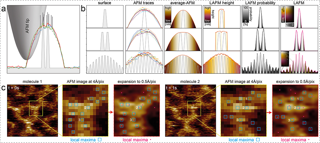
Under specific conditions, i.e. an atomically sharp tip and rapidly decaying tip-sample interaction forces, atomic resolution is attainable on flat incompressible materials such as mica by conventional AFM imaging.18 Achieving and maintaining such conditions on biological samples, which are not only soft and dynamic but also immersed in liquid at room temperature, is not possible. Typically, the tip geometry from apex up to the height of the objects being imaged is much larger than the separation distance between features of interest (Fig. 1a,b, surface). The finite tip radius results in convoluted lateral dimensions. The signal is further obstructed by noise in the z-direction and stochastic fluctuations of flexible protein surface features (Movie 1) in x-, y- and z-directions (Fig. 1b, AFM traces). Averaging several of these traces removes noise and results in a noise-free topography trace but the tip convolution remains the limiting factor (Fig. 1b, average-AFM). By applying localization algorithms that detect the local maxima in the same series of traces (Fig. 1b, crosses in AFM traces) and extracting the location-specific heights (Fig. 1b, LAFM height) and merging the individual detections in a peaking-probability map (Fig. 1b, LAFM probability), the surface structures are reconstructed with greater lateral resolution in a Localization AFM (LAFM) map (Fig. 1b, LAFM). Using local peak-search algorithms, peaking local maxima in AFM data has previously been performed and merged into probability density maps from which energy landscapes were calculated to sample the conformational space of protein moieties27 and derive stiffness maps.7 Here we built on this concept and extended the approach leveraging the novel methodological knowledge generated by the development of super-resolution fluorescence localization microscopies.24,3 Localization-based fluorescence microscopy methods taught us that a resolution superior to the physical limitations can be achieved, when the localization of isolated signals are determined with high spatial precision in many images, later merged in a compiled map.3 This map has the lateral resolution of the spatial localization precision of the signals, which is much higher than the lateral resolution of the initial data. Advantage is taken that the peak position of signals with wide intensity distributions can be determined with astonishing precision. Here, we adapted this transformative rationale to AFM data (Extended Data Fig. 1e–h). First, the pixel- and/or AFM-restricted low lateral resolution data is oversampled to allow peak positions to be determined with increased spatial localization resolution. Peak positions are measured and localization data is then merged to give a reconstructed map with higher lateral resolution than the initial pixel sampling and/or technique allowed (Fig. 1b, compare LAFM with average-AFM).
Figure 1). Principle of Localization AFM (LAFM).
a) Schematic of an AFM tip scanning a high topography with high-resolution features. Dashed line: Theoretical contour. Colored lines: 3 representative simulated topography traces. Open symbols and lines: Vertical and lateral positions of detected local maxima. b) Simulations (n = 1,000) of the LAFM method on surfaces with one (top), two (middle) or many height-modulated (bottom) surface features. From left to right: Surface: Representation of idealized surface features (grey). AFM-traces: 9 representative simulated topography traces (colored lines), with detected local maxima (crosses). Average-AFM: Average topography (n = 1,000). LAFM height: Average height value of detected local maxima. LAFM probability: Peaking-probability distribution of detected local maxima. LAFM: LAFM map merging real-space height with peaking-probability. Insets: False color scales: height, probability and height/probability. (c) High spatial resolution topography local maxima detection: Panels 1, 4: Two representative sequential (t=0s, t=1s) raw data images of an A5 trimer. Panels 2, 5: Magnified views of raw data (4Å/pix). Blue squares: local maxima pixels. Local maxima labeled 1, 2, and 3 are detected at identical pixel locations in both images. Panels 3, 6: Same image regions after image expansion (0.5Å/pix). Red squares: local maxima pixels.
The LAFM map reconstruction is best illustrated in the simulation where several features of varying height are contoured next to each other (Fig. 1b, bottom row). Simulations show the LAFM algorithm detects features that are hidden to theoretical and average topographies (Fig. 1b, Extended Data Fig. 3) with a peaking-probability that is non-linear with the protrusion height if there are closely neighboring higher features, performing best on flat samples (Extended Data Fig. 2). Each pixel in these maps contains both the height and probability information (Fig. 1b, bottom right). Further simulations varying tip radius and shape on simple (Extended Data Fig. 4, Movie 2) and more complex (Extended Data Fig. 5) model 3D surfaces showed the LAFM algorithm outperforms averaging methods within 10–100 images, showing the greatest improvement in resolution (~1/5) for tip radii greater than the separation of the structural features. These analyses corroborate that the quality of the LAFM map increases with increasing number of observations until it plateaus, when between ~50 (for a sharp tip) and ~500 (for a blunt tip) particles are analyzed.
On real AFM data, detection of local height maxima is performed after image expansion (Fig. 1c). Image expansion using bicubic interpolation (see Methods) does not increase the lateral resolution of the topography but allows detecting local maxima with far greater spatial precision (Fig. 1c, compare panels 2 and 5 with 3 and 6). Merging the high-precision local maxima from several particles results in resolving structural features with separation distances shorter than the initial pixel sampling. To retain the topographic structural information, the topography height value from each peak location is carried into the LAFM reconstruction where height and peaking-probability are encoded by a 2D false-color scale in which the green/red ratio scales linearly with height h, and the probability p from white at p=1 to black at p=0 (Extended Data Fig. 1i,j). Furthermore, each peaking detection, originating from an atomic tip-sample interaction, is assigned a 2D-Gaussian density function decaying from 1 to 0 over 1.4Å to approximate atomic solvent-accessible surface areas. A reconstructed LAFM map thus compiles, from many particles, the average topography height refined by the peaking-probability (Fig. 1b, right), where each pixel carries the full information about topography and its likelihood of being detected at this location. In merging many particles, randomly distributed apparatus noise does not merge into consistent height/probability data. Conversely, peaking detections that emerge from protein surface fluctuations will merge into strong localized signals in high-resolution reconstructed LAFM maps.
Single amino acids on protein surfaces
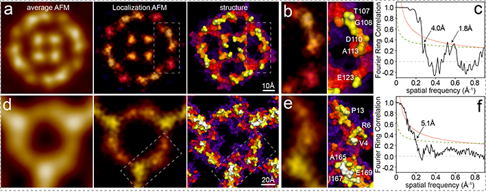
To illustrate the power of the LAFM approach, we first applied it to a former conventional AFM dataset.20 After extraction and alignment of aquaporin-Z (AqpZ) tetrameric channels, the LAFM map revealed details comparable to the surface of the X-ray structure (Fig. 2a, Movie 3), resolving single amino-acids on surface protruding loops (Fig. 2b). Line profile analysis and image comparison between the average AFM topography, previous peak probability mapping methods27 and LAFM probability maps of independent dataset half-maps show LAFM’s ability to detect previously hidden structural features (separated by 2.6Å) well beyond the details resolved by previous averaging and peak probability methods (11Å) and the Nyquist frequency of the raw data (1/6.6Å) (Extended Data Fig. 6a–i). Interestingly, among the AqpZ X-ray structures, E31 in the central a-loop is in different orientations, and the LAFM map indicates that in physiological buffer the E31 rotamer configuration as found in PDB 2ABM is preferred (Extended Data Fig. 6j). We also applied the LAFM approach to annexin-V (A5) trimers extracted from HS-AFM movies5,9,28 (Fig. 2d, Movie 4) and found that the LAFM map resolved fine structural details (while the average only resolved the protein envelope) along the backbone of the molecule (Fig. 2b). HS-AFM’s capability to acquire dynamic imaging will allow time-resolved LAFM reconstructions (see Discussion).
Figure 2). Localization AFM (LAFM) of AqpZ and A5.
a), b) and c) AqpZ: Data acquisition: AqpZ reconstituted in DMPC/POPC (1/1) membranes imaged by conventional AFM in contact mode: Scan speed: 6.8 lines/s, scan area: 169nm, image size: 512pixel, pixel sampling: 3.3Å/p.20 d), e) and f) A5: Data acquisition: A5 on a DOPC/DOPS (8/2) bilayer imaged by HS-AFM in amplitude modulation mode: Scan speed: 1 frame/s, scan area: 80nm, image size: 200pixel, pixel sampling: 4.0Å/p. a) and d) left: Average AFM maps. Middle: LAFM maps, pixel sampling: 0.5Å/p (AqpZ: n = 128; A5: n = 698, filtered to 5Å) Right: Surface representations of X-ray structures: AqpZ: PDB 2ABM, A5: PDB 1HVD. b) and e) Detail views of the LAFM maps and X-ray structures with recognizable residues labeled. c) and f) FRC analyses of LAFM half-maps.
To quantitatively assess the resolution of the LAFM maps, we applied the Fourier Ring Correlation (FRC) method, developed for electron microscopy29 and more recently adapted for super-resolution fluorescence microscopy.26 The FRC method splits the datasets into halves and assesses their statistical resemblance as a function of the resolution range. This analysis resulted in 4.0Å for AqpZ, 5.1Å for A5 and 4.5Å for A5 P13W-G14W (Fig. 2c,f, Extended Data Fig. 7a,b,h). The FRC curve of AqpZ has, in addition to the signal power up to ~4.0Å, a second information-containing range in the 2Å-regime. Thus, LAFM half-map analysis of AqpZ not only shows conserved real-space structural features separated at distances shorter than the Nyquist frequency of the raw data (Extended Data Fig. 6h,i), but also statistical analysis of half-maps report signal power at such high resolution. Accordingly, LAFM maps of both AqpZ and A5 resolve details down to the amino-acid size range (~5Å to ~4Å), and some signal power on the quasi-atomic scale (~2Å) in the case of AqpZ (Fig. 2b,c, Extended Data Fig. 6). We also capitalized on the serendipitous co-existence of two differently oriented A5-trimers in the A5-lattice. LAFM of the two trimer datasets, independent from each other and acquired through different relative AFM scan-directions, agree in great detail (Extended Data Fig. 7c,d,e). Finally, we cloned, expressed and purified a mutant A5, replacing two amino acids in the N-terminus to tryptophans (P13W, G14W) and imaged the A5-mutant by HS-AFM (Extended Data Fig. 7f,g,h). LAFM maps of the A5-mutant show overall rearrangements of the N-terminus with increased height and peaking-probability at the mutation site.
Localization AFM of CLC antiporters
The AFM data of A5 and AqpZ have been acquired on 2D-lattices however, a considerable advantage of LAFM is that the biomolecules do not need to be confined in a crystal for analysis but can be sparsely populating a native-like environment. Furthermore, the buffer conditions inside the fluid cell can be changed to assess structural changes in response to environmental changes. Therefore, we studied CLC-ec1, a Cl−/H+ antiporter from E. coli,30,31 that to our knowledge has never been observed before by AFM, and for which questions about the transport mechanism remain unsolved. Mutations in human CLC family homologs have been associated with diseases.32
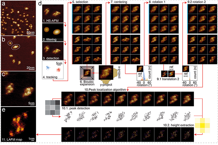
HS-AFM of CLC-ec1 in membranes formed through proteo-liposome fusion showed a dispersed population of proteins protruding 1.2nm from the membrane (Fig. 3a–c, Movie 5). CLC-ec1 was predominantly dimeric, with small populations of monomers and higher-order oligomers assembled from multiple dimers (Fig. 3b). The topography and lateral dimensions of the dimers (Fig. 3c) were consistent with the 5.5 × 9.6nm dimensions of the extracellular face of CLC-ec1 (Extended Data Fig. 8a–e).33,34 Because the dimers were not confined they exhibited translational and rotational freedom (Fig. 3c, Movie 5), which led us to establish a generalized LAFM workflow (Fig. 3d, see Methods): (1) a HS-AFM video is acquired, and (2) low-pass filtered, so that (3) particles can automatically be detected. Particles are thus (4) tracked throughout the HS-AFM observation and (5) selected and extracted in a gallery. (6) Bicubic image expansion allows for (7) precise particle centering and (8) rotational alignment to an arbitrary molecule reference. A second cycle of (9.1) lateral and (9.2) rotational alignment, this time with respect to an ensemble average, prepares particles for (10) application of the LAFM method (Movie 6). As described in figure 1, (10.1) local maxima peaks are detected and (10.2) the height at these locations is extracted with a 1.4Å wide probability radius. Finally, all detections are merged in a height/probability LAFM map (Fig. 3e). The particle gallery (step 5) can be assembled from many molecule observations in one or several frames. Alternatively, a LAFM map can be reconstructed from one molecule observed over time, which gives this method unique possibilities to access high-resolution information of individual molecules.
Figure 3). HS-AFM imaging and LAFM workflow of CLC-ec1.
HS-AFM images of CLC-ec1 in a POPE:POPG (2:1, w:w) membrane at (a) 400nm (300 pixels), (b) 120nm (300 pixels) and (c) 40nm (300 pixels) image (frame) size of predominantly dimeric CLC-ec1 at low density in a membrane. (d) LAFM method workflow steps: 1) HS-AFM movie acquisition 2) Image Gaussian filtering. 3) Molecule detection. 4) 2D-tracking to separate single molecules (molecules highlighted blue or red could be treated individually). 5) Molecule selection. 6) Bicubic expansion (original pixel sampling: 1.33Å/p, expanded pixel sampling: 0.5Å/p). 7) Molecule centering (1st round) by center of mass. 8) Rotational alignment (1st round) of molecules through rotational cross-correlation with a reference frame. 9) Translational and rotational alignment (2nd round) through cross-correlation with the average molecule from step 8 (inset histograms: rotation angles distributions for all particle in steps 8 and 9). 10) LAFM method: Input: aligned HS-AFM images (n = 200). 10.1) LAFM peak detection of local maxima. 10.2) Height extraction at each peak position and application of a 1.4Å localization probability distribution. 11) LAFM map reconstruction through merging of all LAFM detections.
Conformational changes in CLC-ec1
The exchange pathway in the CLC-ec1 Cl−/H+-antiporter has been proposed to have two separate entrances/exits for H+ and Cl− on the intracellular face, converging to a central binding region from which both ions follow the same path to the extracellular side. However, there is debate whether the gating mechanism requires only localized side chain motions in the Cl−-pathway based on X-ray structures, or if greater movements occurred as evidenced by NMR,35,36 computational37 and helix-crosslinking studies38. The findings by non-crystallographic methods35,36,37,38,39, led to suggestions that confinement of CLC in 3D-lattices inhibited large conformational movements (Extended Data Table 1, Extended Data Fig. 8f), similar to other transporters.40–43 Cl−-transport by CLC-ec1 is maximal at acidic pH and stalled at neutral and basic pH (due to pH-dependent activation and lack of H+ as substrate).44 A more recent structure of a protonation-mimicking triple-mutant also indicates conformational rearrangements.45 Therefore, we performed HS-AFM of transporters sparsely packed in lipid membranes and in physiological buffer. Subsequent LAFM of the pH 7.6 (inactive state) and pH 4.5 (active state) observations should inform if large-scale conformational changes occurred.
Based on the X-ray structure surface (Fig. 4a), we assigned the protruding residues expected to give signals in AFM: Asp73 in loop B-C, Glu235, Asp240 and Lys243 in the long loop I-J, Asn327 in loop L-M, and Gln381 and His383 in loop N-O. To refine the interpretation of LAFM reconstructions, we used molecular dynamics (MD) simulations to convert the static X-ray structure into a dynamic molecular system fluctuating at room temperature and at pH 7 (Movie 1). Alike the LAFM method, we plotted a population density map of the distribution of the Z-coordinate local maxima on the CLC-ec1 extracellular face from MD trajectories, which reflected side-chain motions of membrane-protruding residues (Fig. 4b, Extended Data Fig. 8g,h). The MD trajectories show how structural fluctuations that are probed (in AFM) and merged (in LAFM), allow extraction of high-resolution information of amino acid residues on protein surfaces.
Figure 4). Conformational changes in CLC-ec1 at neutral and acidic pH.
a) Extracellular surface of CLC-ec1 at pH 9.5 (PDB 1OTS31), membrane-protruding residues in four major protrusions (1–4) are labeled. b) Log-scale population density map of the positions of atoms with the highest Z-coordinates on the extracellular surface of CLC-ec1 from 5.6 μs MD simulations at pH 7 (simulated from PDB 1OTS). Major protrusions (1–4) are labeled. Major contributions to each population peak: 1) D73 (97%), A72 (2.7%); 2) N237 (91%), D240 (2.2%); 3) Q381 (42.3%), H383 (54.7%); 4) K243 (52%), D240 (21.7%), S245 (3.4%). LAFM reconstructions of CLC-ec1 at (c) pH 7.6 and (d) pH 4.5. The ion pathway entry is labeled (*). The four major protrusions (1–4) are highlighted for comparisons with the X-ray structure and the MD population density map. e) Peaking-probability difference map between CLC-ec1 LAFM reconstructions at (c) pH 7.6 and (d) pH 4.5. The difference map highlights the conformational changes of the four major protrusions, notably a ~6Å movement of peak 1 towards the dimer axis.
The CLC-ec1 LAFM reconstructions at pH 7.6 and pH 4.5 display the same set of structural features as the X-ray structure and the MD population map, but in distinctly different configurations (Fig. 4c,d). Peaks 2, 3 and 4, which form a triangle close to the dimer interface, pack more loosely at pH 4.5, and peak 3 moves towards a more lateral position on the dimer, while the most remarkable conformational change is a ~6Å movement of peak 1 towards the dimer-interface at acidic pH. The extracellular Cl−/H+ ion pathway lies between Asp73, Asn327 and Glu235 (Fig. 4c, asterisk), thus, under the premise that these displacements were related to movements in the underlying helices, these structural changes might alter accessibility to the extracellular gate. In summary, LAFM reports large pH-dependent conformational changes (Fig. 4e, Movie 7).
By recording 3D topographic images and movies, AFM and HS-AFM offer rich data, captured through many atomic interactions between tip and sample in liquid and at ambient conditions. By pinpointing peak interaction locations with high spatial precision in oversampled topographies, LAFM produces quasi-atomic resolution maps of protein surfaces from such data. We demonstrate LAFM’s ability to detect amino acid side chains on the surfaces of AqpZ, A5 and CLC-ec1, mutation-related differences in A5, and conformational changes in the Angstrom-range in CLC-ec1. Our LAFM maps calculated from CLC-ec1 imaged at physiological and acidic pH identified significant differences in the central region, where helices N and O are located (peak 3, and close-by peaks 2 and 4), and at the peripheral end of helix B (peak 1) which moves towards the dimer center, giving the entire molecule an ~1.2nm shortened appearance (Fig. 4d,e).
HS-AFM5 operates in amplitude modulation mode using short cantilevers that oscillate at resonance ~660kHz (oscillation cycle ~1.5μs). The tip touches the surface only during ~10% of an oscillation cycle,4 thus ~150ns. While this is a short period even in the life of a protein, side chain fluctuations occur in such time-regimes, thus blurring the signal. Hence, LAFM will provide improved data, when the next generation of faster HS-AFMs will be built. Today, amplitude detectors oversample the cantilever,5,46 but feedback operation and the z-piezo are limiting (~100kHz) and need improvement.
The LAFM method, can be used in two different ways: LAFM maps can be reconstructed (i) from many molecules recorded in one or several frames, or (ii) from single molecule over time. The first approach allows to resolve time- or environment-dependent conformational changes. ~50 particles are needed to reconstruct a LAFM map (Extended Data Fig. 5). Thus, the temporal resolution of LAFM is decreased to the time to accumulate ~50 observations. Faster HS-AFM operation will help. Alternatively, imaging densely packed proteins (~50 particles in each frame8,47) would allow LAFM map reconstruction of the proteins’ conformation in each frame giving high-resolution structural changes as a function of time. The second approach gives the method the unique capability to provide high-resolution information of single molecules or of non-ordered supramolecular assemblies. Altogether, we envisage LAFM will become the standard method applied to AFM imaging, allowing the extraction of high-resolution information beyond the tip-radius resolution limit in the study of single biomolecules in native-like environments.
Methods
High-Speed Atomic Force Microscopy (HS-AFM)
HS-AFM measurements in this study (annexin-V, CLC-ec1) were taken by amplitude modulation mode HS-AFM (RIBM, Japan), as previously described in Miyagi et al. 2016.28 In brief, short cantilevers (USC-F1.2-k0.15, NanoWorld, Switzerland) with spring constant of 0.15N m–1, resonance frequency of ~0.66MHz and a quality factor of ~1.5 in buffer, were used.
Atomic Force Microscopy (AFM)
AFM data (aquaporin-Z) were taken by contact mode AFM using a Nanoscope-III AFM (Digital Instruments, Santa Barbara, CA) equipped with a 120 μm scanner (J-scanner) and oxide-sharpened Si3N4 cantilevers with a length of 120 μm (k=0.1 N/m) (Olympus Ltd, Tokyo, Japan), as detailed in Scheuring et al.20
Cloning, expression and purification of Annexin-V-P13W-G14W
The P13W-G14W site-directed mutagenesis was performed on an untagged human-Annexin pET28a expression vector using the Q5 site-directed mutagenesis kit (New England BioLabs, MA, USA) and the following mutagenic primers (mutated nucleotides are in bold):
5’-GACCGATTTTTGGTGGTTTGATGAACGTGCTGATGCC-3’
5’- ACGGTACCACGCAGCACTTG-3’.
The mutated genes were sequenced to confirm that only the desired mutations were inserted into the plasmid. The Annexin-V-P13W-G14W plasmid was then transformed into BL21 (DE3) pLysE chemically competent E. coli cells (Invitrogen), and grown overnight at 37°C for small-scale culture. The overnight culture (50ml) was inoculated into 2L fresh LB media at 37°C, and once an optical density (A600) of 0.6–0.8 was achieved, the cells were induced by addition of 0.4mM IPTG. After induction for 4h, the cells were separated from the culture medium by centrifugation (5,000g; 20min) and resuspended in ice-cold calcium buffer (50mM Tris pH7.5, 10mM CaCl2). The suspension was 3 times tip-sonicated on ice for 5 minutes (one pulse every 9s), and centrifuged (23,000g; 45min). The supernatant was discarded, and the pellet was resuspended in ice-cold EGTA buffer (50mM Tris pH7.5, 60mM EGTA). After gentle shaking for 30min, the cell debris were removed by centrifugation (23,000g; 45min), and the supernatant containing the soluble Annexin-V-P13W-G14W was dialyzed overnight against buffer A (20mM Tris pH7.5, 20mM NaCl). The solution was applied to a HiTrap DEAE FF sepharose column (5ml), ÄKTA Avant (GE Healthcare Life Sciences), and eluted with a linear gradient of 0–1 M NaCl. Fractions containing Annexin-V-P13W-G14W (based on SDS-PAGE analysis) were concentrated to ~1mg/ml using 10kDa centrifugal filters (Amicon, Millipore), and subjected to a final purification step with a Superdex 200 Increase 10/300 gel filtration column (equilibrated with 20mM Tris pH7.5, 100mM NaCl buffer), reaching a final purity of >95% based on SDS-PAGE analysis.
CLC-ec1 expression and purification
Expression and purification of CLC-ec1 was carried out as previously described.48 BL21-AI E. coli competent cells (Thermo Fisher Scientific, Waltham, MA) were transformed with the plasmid and then 2 L Terrific Broth supplemented with ampicillin was inoculated and grown at 37°C. Protein expression was induced with anhydro-tetracycline at OD600 = 1.0. After 3 hr of induction, cells were harvested, then lysed by sonication in buffer supplemented with 5 mM reducing agent TCEP (Tris(2-carboxyethyl)phosphine; Soltec Bioscience, Beverly, MA) and pH adjusted to 7.5. Protein extraction was carried out with 2% n-Decyl-β-D-Maltopyranoside (DM; Anatrace, Maumee OH) for 2 hr at room temperature. Cell debris was pelleted down and the supernatant was run on a 2 mL column volume (CV) TALON cobalt affinity resin (Clontech Laboratories, Mountain View, CA) equilibrated in cobalt column wash buffer (CoWB)/TCEP: 100 mM NaCl, 20 mM Tris, 1 mM TCEP, pH 7.5 with NaOH, 5 mM DM. After binding, the column was washed with 15 CVs of CoWB/TCEP followed by a low imidazole wash of CoWB/TCEP containing 20 mM imidazole (Sigma-Aldrich, St. Louis, MO). CLC-ec1 was eluted with CoWB/TCEP containing 400 mM imidazole, then concentrated in a 30 kDa NMWL centrifugal filters (Amicon, EMD Millipore) to ~500 μL and injected on a Superdex 200 10/30 GL size exclusion column (GE Healthcare, Little Chalfont, UK) equilibrated in size exclusion buffer (SEB): 150 mM NaCl, 20 mM MOPS pH 7.5, 5 mM analytical-grade DM, attached to a medium pressure chromatography system (NGC, Bio-Rad).
CLC-ec1 Reconstitution and Bilayer Formation
Lipids were resuspended in 300 mM KCl, 20 mM Citrate pH 4.5 with NaOH. CHAPS (35 mM) solubilized lipids were combined with protein at 100 μg CLC-ec1 per 1 mg of lipids, corresponding to 7.6 × 10⁻⁴ protein/lipid mole fraction (assuming a 50% incorporation yield).48 The protein-lipid-detergent mixture was dialyzed in cassettes (NMWL 10 kDa; ThermoFisher Scientific) at 4°C against 4 L of buffer for 48 hr with buffer changes every 8–12 hr. After completion of dialysis, the proteo-liposomes were harvested from the cassettes, freeze/thawed and then extruded using an Avanti Polar Lipids Mini Extruder (Alabaster, AL) through a 400 nm membrane. 1.5 μl of the SUV solution with a total lipid concentration of 0.1mg ml s−1 was deposited onto freshly cleaved mica to form SLBs through vesicle fusion. The excess lipids, after SLB formation, were rinsed first with deionized water followed by buffer. For experiments at pH 7.6 the sample was rinsed with 25mM Tris, 300mM KCl pH 7.6.
Image expansion
AFM topography images were expanded using bicubic interpolation (Catmull-Rom interpolation; implemented in imageJ (NIH, USA), scripted using the method of Burger and Burge).49 The method considers values over a 16-pixels surface (4×4 pixels) to calculate the new intermediate surface, p(x,y) created by expansion across the central 2×2 area. The interpolated values are approximated by 3rd order polynomials in both x and y directions:
Where i and j are the order of the polynomial for x and y respectively and aij are 16 possible corresponding coefficients. The resulting polynomial can be calculated using the values at the four corners of the central 2×2 grid (f(x,y)), the gradients at each of those positions in the x and y directions (fx(x,y), fy(x,y)) and the cross derivatives (fxy(x,y)) requiring the 4×4 pixel grid with the derivatives being calculated numerically. The interpolated surface, p(x,y) between four corner pixels can be described by:
Where the 16 coefficients can be calculated using the values and derivatives at the 4 corners:
Using this method all our datasets were resampled to 0.5Å/pixel as indicated in the figure captions. The reason for expanding to 0.5Å/pixel is based on approximating the picked maxima features to the solvent accessible surface of atoms with gaussian profiling as detailed in the Methods section ‘Peaking-probability’. By constructing the interpolant value from continuous piecewise polynomials, the result is always continuous. This works particularly well for interpolation of smooth areas as in the case of tip radius limited imaging, and therefore significantly improves local maxima localization but does not increase image resolution.
Detection of local maxima
A local maximum position (Fig. 1c) is defined if a given pixel is higher than all the surrounding 8 pixels in a 3×3 pixels grid (Fig. 1c, Fig. 3d). This 3×3 pixels grid is ‘scanned’ pixel-by-pixel over the image, thus all pixels (with the exception of the pixels at image borders) in each particle image are checked for maxima. To reduce selection of maxima due to noise in certain data sets, a noise tolerance algorithm that selects maxima based on their prominence above surrounding maxima was implemented. The prominence of each maximum, pi is calculated by the following steps: i) search for the closest neighboring maxima hn with a higher height than the current maxima hi or closest image boundary, ii) find the minimum height along the profile between hi and hn or hi and the image boundary, iii) define the peak prominence as:
In our method for a local maximum to be selected its prominence must be greater than the noise tolerance (typically 1–2 Angstrom). In our plugin the noise tolerance is defined by the user from 0 to 100%, where the noise tolerance parameter corresponds to the range of height values from lowest to highest in the image. These maxima selection criteria are based on the noise level of the AFM imaging and the typical RMS fluctuations at protein surfaces (Extended Data Fig. 8g,h). An alternative method is to apply a gaussian filter to the image to reduce noise and use 0% noise tolerance. The repulsive interaction forces between the farthest exposed atoms of the tip and the atoms in protein moieties that protrude most have very steep separation distance dependence. Very strong short-range interactions occur including Pauli repulsion, van der Waals, hydration, steric and ionic forces, which depend on the surface properties of both the AFM tip and the protein.50 As a result the most exposed atoms dominate local topographic detection and high-resolution information can be obtained through merging many tip-sample atomic interactions at different localizations and time points or on different molecules of the same kind.
Peaking-probability
The peaking-probability at a given localization in a LAFM map, is the cumulative probability that a pixel (in the expanded image) is detected within all particles analyzed. It is the sum of: picking events (n) multiplied by the power of the 2D-Gaussian, g(0<p<1) on each pixel, divided by the total number of particles merged (N).
The 2D-Gaussian in all our datasets was set to 1.4Å width to approximate the solvent-accessible surface of the underlaying atoms (the solvent-accessible surface area is defined as the surface traced out by the center of a water sphere rolled over the protein atoms),51 whilst imparting a continuous probability density to each discreetly selected maximum. The application of larger Gaussian radii to approximate the atomic origin of the tip-sample interactions or pre-filtering the data before peaking leads to loss of resolution or loss of peaking detection of lower features, respectively (Extended Data Fig. 9). Since AFM can reproducibly image atoms on solid surfaces, eg on mica, the piezo-elements that mediate the scanning of the AFM sample stage have sub-atomic X-Y position precision.
Height extraction
The real-space topographic height is extracted at each picking event to produce a set of N matrices containing height values for each value of n. This matrix is then false colored to allow distinction between height and probability information.
Merging height and detection probability
The false colored extracted height values in each image are then multiplied by the greyscale probability values in each image and then averaged for the whole image set to reconstruct a LAFM map.
LAFM workflow
The HS-AFM movies were 1st-order flattened to compensate for sample stage tilt, drift corrected and contrast adjusted by laboratory-built image analysis software in ImageJ and MATLAB (Matlab, Mathworks, Natick, MA, USA). The workflow to calculate a LAFM map from molecular HS-AFM raw data is outlined in figure 3. The key steps in the preparation for the LAFM method are: the extraction of molecular observations from images (Fig. 3d, steps 1–5), image expansion (Fig. 3d, step 6, see Methods paragraph ‘image expansion’), the creation of a particle gallery with laterally and rotationally well-aligned particles (Fig. 3d, steps 7–9). Several image processing packages used for EM (e.g. 52) allow particle extraction and alignment, and could be used for convenience. The particle gallery of pixel expanded (0.5Å/pixel) molecular observations is the entry for the LAFM algorithm, which comprises detection of local maxima, height extraction, and merging of height and peaking probabilities (Fig. 3d, steps 10–11; Methods paragraphs ‘detection of local maxima’, ‘peaking-probability’, ‘height extraction’ and ‘merging height and peaking-probability’) in the final LAFM map. The LAFM method is available as code in the form of an appendix and as an ImageJ plugin (Supplementary Material).
LAFM Simulations
2D and 3D LAFM simulations were performed using MATLAB (Matlab, Mathworks, Natick, MA, USA). In 2D simulations (x, z) various model surfaces were created with different features depending on the simulation (Fig. 1b: Simulation parameters: Tip radius = 20, feature height = 3, feature width and separation = 2, scanning noise = 0.05 (sd), feature fluctuation = 0.3 (sd), gaussian surface topography (bottom row) has standard deviation (σ) of 20, varying parameters are used in Extended Data Fig. 2, Extended Data Fig. 3 given in the figure captions). Each topographic feature was given a height higher than the surrounding baseline surface (set at zero). Normally, distributed random numbers with set standard deviation were then generated and added to each x position containing a topographic feature, increasing or decreasing the height. These random fluctuations were added independently of neighboring x positions. A semicircular tip of defined radius was calculated numerically and then scanned across the simulated 2D-surface to create a tip convoluted topography. To simulate AFM instrument noise, normally distributed random noise was then added in the z-direction to the tip convoluted topography at all positions. Many randomly generated topographies were then analyzed using the LAFM algorithm to produce peaking-probability and peaking height traces. 3D-simulations were run using a similar methodology however a hemispherical tip was scanned across 3D model surfaces (Extended Data Fig. 4, Extended Data Fig. 5, Movie 2).
Simulation data is compared to a theoretical resolution limit (Extended Data Fig. 3) based on geometric considerations, assuming a rigid pair of spikes separated by a distance (d) and height difference (Δh) contacted by a tip radius (R) without noise or fluctuations. The resolution limit is defined as being resolved if the probe is able to reach a minimum (Δz) below the height of the smallest spike53:
The absolute resolution limit under these considerations occurs when maxima can be detected at both spikes when Δz = 0.
Molecular dynamics simulations: CLC
Construct for molecular dynamics (MD) simulations:
The molecular model of the CLC-ec1 dimer used in all MDS described in this work was based on the X-ray structure PDB 1OTS.31 The protonation states of the titratable residues at pH 7 were determined from constant pH calculations with the neMD/MC (non-equilibrium MD / Monte-Carlo) approach.54 The spatial arrangement of the CLC-ec1 dimer in the bilayer was optimized using the Orientations of Proteins in Membranes (OPM) database55 and inputted to the Membrane Builder module on CHARMM-GUI web server56 to assemble protein-membrane system. The CLC-ec1 dimer was embedded in a 629-lipid membrane bilayer containing a ~70:30 mixture of POPE (1-palmitoyl-2-oleoyl-sn-glycero-3-phosphoethanolamine) and POPG (1-palmitoyl-2-oleoyl-sn-glycero-3-phospho-(1’-rac-glycerol)), solvated in 150 mM KCl explicit water to achieve electroneutrality.
Molecular dynamics simulation procedures:
The assembled molecular system was subjected to an initial equilibration phase using NAMD57 (version 2.13) following two protocols. The first used the standard 6-step equilibration protocol provided by CHARMM-GUI. The other used a lab-built multi-step equilibration, in which the backbone of the protein was first fixed.58 Backbone constraints were gradually released in three 300 ps steps of force constant change (1, to 0.5, and 0.1 kcal/(mol Å2)). The final structures from the equilibration phases were subjected to short (46ns and 48ns) unbiased MD with NAMD (2fs time-steps, vdwForceSwitching option, and PME for electrostatic interactions).59 The runs were in the NPT ensemble under semi-isotropic pressure coupling, at 24°C. The Nose–Hoover Langevin piston algorithm60 was used to control the target P = 1 atm pressure with LangevinPistonPeriod of 50 fs and LangevinPistonDecay of 25 fs. Van der Waals interactions had a cutoff distance of 12 Å. The first phase of production runs (Production 1) was initiated by all atom velocity resetting and continued with simulations of the system in 50 independent replicates of ~150ns each (i.e. 100 replicates overall for a cumulative 15 μs) using ACEMD.61 At the conclusion of the Production 1 phase, the trajectories were analyzed to assess the stability of the bound Cl− ions, and replicates with the most stably bound Cl− ions were identified. The final snapshots from 48 replicates were selected as starting points for the next, Production 2 phase, in which the systems were simulated using NAMD with the parameters described above for ~120 ns (cumulative 5.76 μs). Run parameters: timestep 4 fs, vdwforceswitching on, switching on, switchdist 7.5, cutoff 9, fullelectfrequency 2, langevindamping 0.1, pme on, and pmegridspacing 1.0. All the simulations used the latest CHARMM36 force-field parameters for proteins, lipids, and ions.
Population density maps from the MD trajectories:
To analyze the height of protein atoms with respect to the membrane plane during the MD simulations, the symmetry axis of the CLC-ec1 dimer was set perpendicular to the XY-plane. In analogy to the LAFM method, the highest Z-coordinate values on the CLC extracellular surface were selected for each frame to plot the position distribution map. Maps were constructed by taking the 8, 10, and 16 highest points in each frame, leading to the conclusion that detection of more than 8 points resulted in sampling the neighboring atoms of residues already included in the 8-point set. Thus, the distribution maps were obtained by pooling the 8 highest Z-coordinate peaks from each frame. The analysis performed separately on Production 1 and Production 2 trajectories did not show notable differences and in the manuscript we show the results from the analysis of 5.6 microsecond with 20 picosecond time strides of Production 2 trajectories. Since both protomers of CLC-ec1 were considered identical, we symmetrized the data by aligning trajectories of each protomer onto another one.
Molecular Dynamics Simulation: Annexin P13W-G14W
MD simulations of the mutant Annexin-V-P13W-G14W was conducted with Gromacs2019.1,62 using the Amber03 force field.63 The initial molecular model of Annexin-V-P13W-G14W was generated using the X-ray structure PDB 1HVD, and the double mutation introduced using the program Coot64. This model was then solvated with ~40,000 water molecules in accordance with the Tip3P water model,65 and neutralized with Na+ and Cl− ions to a concentration of 150 mM. The system was placed in a dodecahedron box, with a minimal distance of 1.0nm between protein and box wall. Van der Waals interactions were implemented with a cutoff at 1.0nm, and long-range electrostatic effects were treated with the particle mesh Ewald method. The protein-solvent model was then put through 4 rounds of geometry optimization and energy minimization, followed by a 50ps protein position-restrained equilibration and an additional 50ps of unrestrained equilibration. The system was then heated to 300K using the velocity-rescaling thermostat66 (50ps), and equilibrated to a constant pressure of 1 bar using the Parrinello-Rahman barostat (50ps). Following these equilibration procedures, a time trajectory of 100ns was simulated at constant temperature and pressure, using time steps of 2fs and the same thermostat and barostat. The data was then symmetrized along the 3-fold axis by aligning trajectories of each protomer one onto the other. To build an Annexin-V-P13W-G14W mutant structural model that represents the rotamer conformations of the mutated Trp residues, clustering analysis of the simulation trajectories was performed with Gromacs (g_cluster, gromos algorithm)62, with an RMSD cut-off of 0.2 with respect to the mutated Trp residues in positions 13–14. Out of the 10 resulting clusters, the most representative structure was extracted from the center of the most populated cluster (containing ~50% of total protein structures).
Extended Data
Extended Data Figure 1|. Localization principles in Photo-Activated Localization Microscopy (PALM) and Localization Atomic Force Microscopy (LAFM).
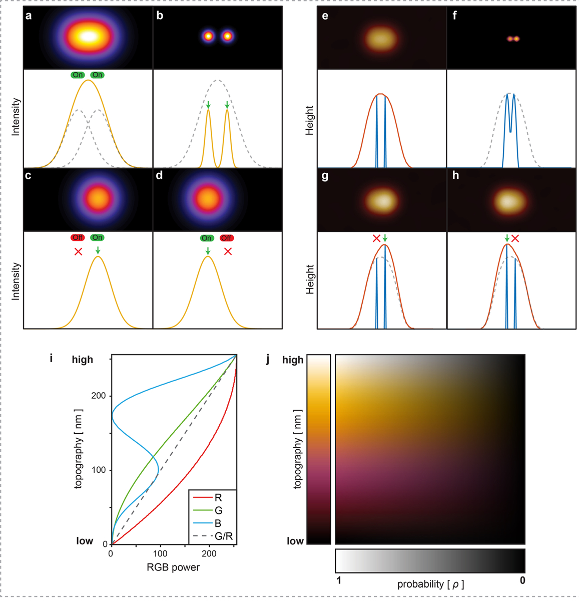
a) A diffraction limited image/profile of two fluorescent molecules located at a separation distance smaller than the diffraction limit. b) Spatially resolved positions of the fluorophores after application of optical localization methods such as Photo-Activated Localization Microscopy (PALM) or stochastic optical reconstruction microscopy (STORM). The position of each fluorophore can be spatially localized with high precision if the emitted signal can be isolated from neighboring fluorophores permitted by stochastic activation of the right (c) or left (d) fluorophore. e) A tip convoluted AFM image of two structural features located at a separation distance smaller than the AFM tip sharpness. f) Spatially resolved positions of structural features after application of Localization Atomic Force Microscopy (LAFM). Stochastic height fluctuations allow the position of each feature to be localized by the protruding height signal of the right (g) or left (h) feature peaking over the neighboring features. In each: Top panels show 2D intensity/topography images, bottom panels show intensity/height profile across the central x line of the top panels. i) and j) LAFM false-color scale to encode topography and localization peaking-probability information. (i) The LAFM map is encoded by a false-color scale in which red (R), green (G) and blue (B) values follow the relations: R(h) = -h2/255 + 2h −2; G(h) = R h/255; B(h) = h(sin(0.036*(h+127))+1)/2, where h is the topography scale and RGB values range between 0–255 (min to max). The ratio of green to red (G/R) values increases linearly with height (dashed line), whilst the blue value increases and oscillates to produce a visually informative false-color scale. (j) To incorporate probability, each picked location is given a Gaussian probability density function that peaks at the value 1. To generate the final LAFM map, the peaks of all molecules are merged, and thus an average topography height and related peaking-probability (gray scale; bottom) at any location is calculated, resulting in a 2-dimensional false-color table where each pixel carries the full information about topography and the likeliness of a topography to be detected at this location.
Extended Data Figure 2|. Simulations of varying cleft height and cleft width and detection of features in varying topographic superstructures by the LAFM algorithm.
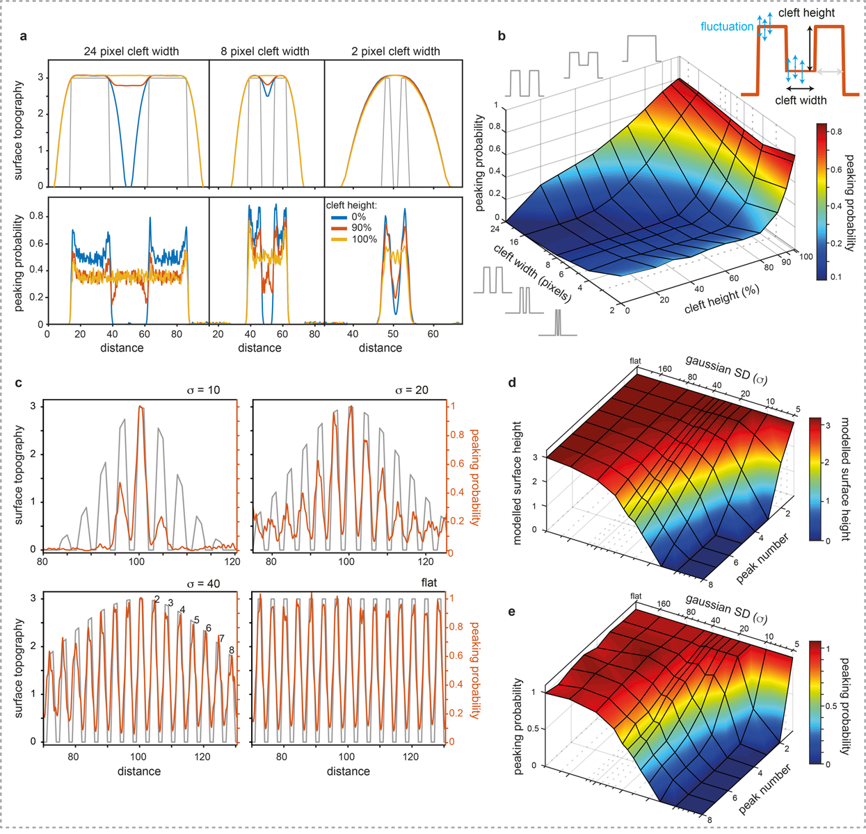
a) Example average surface topography (top) and peaking-probability (bottom) for 24, 8, and 2 pixels cleft width and cleft heights of 0, 90 and 100%. At 2 pixels separation (cleft width) averaging is unable to detect any topography change as the cleft height is changed because the tip never probes into the cleft. In contrast, the LAFM method reports lower peaking probabilities in this region separating the two features. The detection probability in the cleft areas is tip radius, feature separation- and height fluctuation- dependent and therefore not linear. The height detection in the cleft areas is the same as the topography (see Figure 1b in the main text). b) Surface plot showing the peaking-probability in the cleft region relative to the pillar positions for varying cleft heights and widths. In the simulations the tip radius is 20 pixels and each surface feature pixel has feature fluctuation standard deviation of 0.3 and fluctuations are independent of neighboring pixels. c) Peak detection of surface features on Gaussian curved surfaces. Features are 2 pixels wide interspersed by 2 pixels multiplied by Gaussian functions with σ=10, 20, 40 and a flat surface, respectively, scanned by a tip with radius 20 pixels (noise=0.3). Surface plots of the d) height of the model surface, and e) relative peaking-probability compared to the probability at the central peak for each gaussian surface topography up to a distance of 8 peaks from the central peak. The probability of peak detection is affected by neighboring peaks and tip radius, leading to a correct representation of the height, but a non-linear relation between surface height and peaking-probability. There is little to no lateral error of localization position detection on peaks of different local height.
Extended Data Figure 3|. Simulations of feature detection with varying topographic height by the LAFM algorithm.
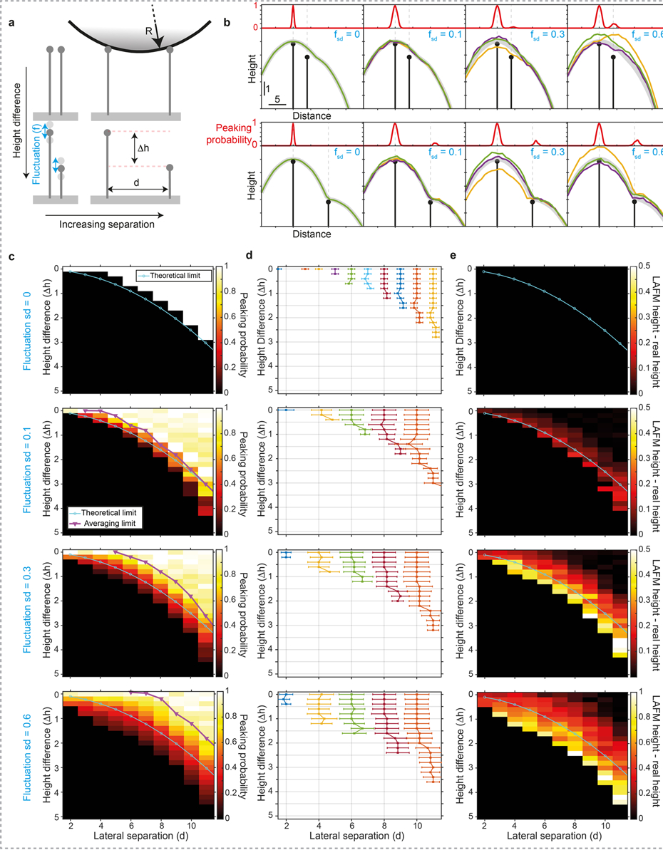
a) Schematic of two sharp features in which the feature separation, d, and height difference, Δh, are varied by changing the position/height of the secondary feature. Feature fluctuations are then simulated by adding or subtracting a randomly generated height (normally distributed), f, with a set standard deviation, fsd, before being scanned by a model AFM tip of radius R. b) Example simulations of topographies with d = 4, Δh = 1 (top) and d = 10, Δh = 3 (bottom) scanned by a tip with a radius R = 20, for varying amounts of feature fluctuation from left to right (fsd = 0, 0.1, 0.3 and 0.6). Colored lines are three representative simulated topography traces and thick grey lines are the average scanned topography (n = 2,000). Panels above each topography plot give LAFM peaking-probability at each position in the topography. c) Matrix of simulations plotted as an image in which each pixel represents the LAFM peaking-probability of the secondary feature for a different height difference / separation distance combination. The black pixels indicate zero probability and therefore no peak detection. Also plotted are the theoretical resolution limits according to geometrical arguments allowing the apex of the tip to contact the feature (see methods, LAFM Simulations) and the average AFM maximum resolution, according to if a local maximum can be detected for the secondary feature in the average topography. d) Lateral position of peaking-probability for the different height difference / separation distance combinations. Each colored line represents a different lateral separation and error bars show the peak width (+/− sd). e) Matrix of simulations plotted as an image in which each pixel represents the difference between the detected LAFM average height and the model height for each height difference / separation distance combination. In c), d) and e) each row represents a different feature fluctuation standard deviation of 0, 0.1, 0.3 and 0.6 from top to bottom. For each fluctuation level, 286 Δh / d combinations were each simulated 2,000 times.
Extended Data Figure 4|. Simulations to assess the ability to resolve two spatial features in localization AFM (LAFM) maps.
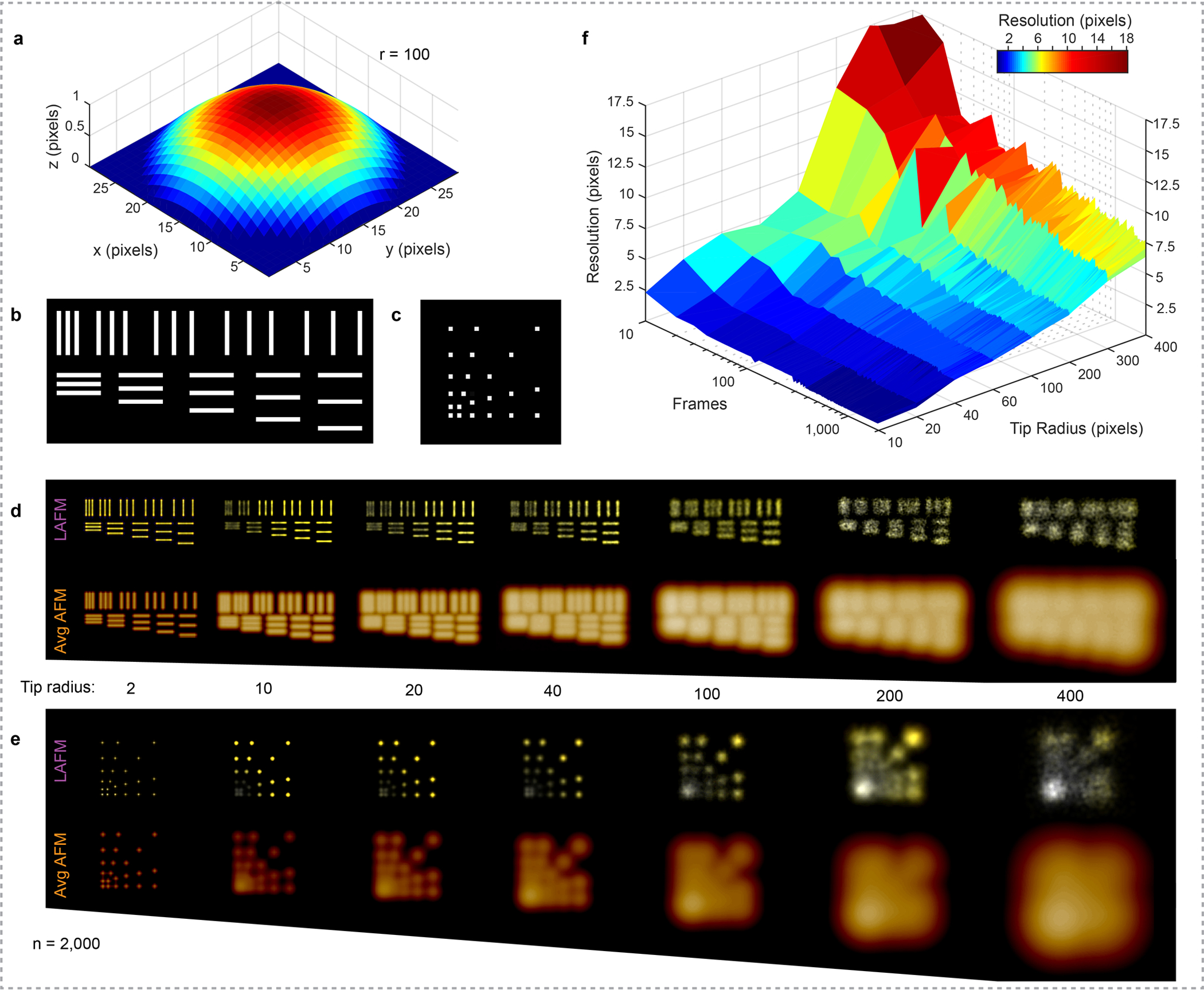
a) A tip with varying tip radius r (here 100 pixels) is scanned over two different simulation surfaces featuring topographic lines (b) or topographic points (c). These lines and points have 1 pixel size in x,y, and z and are interspaced by 1, 2, 3, 4 and 5 pixels. This procedure, including sample fluctuations and contouring noise, results in individual simulated topography images for the line topography (d) and the point topography (e) that are either averaged or analyzed using the localization AFM algorithm (Average AFM and LAFM maps are results from merging 2,000 simulated topographies). f) Surface plot of the simulated LAFM map resolution determined by Fourier ring correlation (FRC) as a function of the number of merged images and simulation tip radius showing that when ~100 particles are analyzed, features of size ~1/40 (for a blunt tip) to ~1/5 (for a sharp tip) of the tip radius can be resolved.
Extended Data Figure 5|. Influence of tip radius and number of merged particles for the calculation of localization AFM (LAFM) maps.
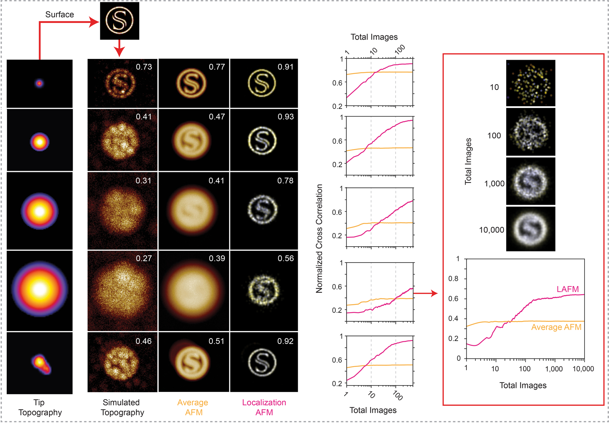
Simulation experiments in which the surface topography (S) with a ring diameter of 35 pixels (top) is probed by (1st column:) 5 different tips, four spherical tips with increasing radius (1–4, R = 10, 100, 300, 600) and an irregular tip with a ‘double-tip’ protrusion (R = 40, peak to peak = 12 pixels). 2nd column: Simulated individual raw data images (comprising random noise) of the topography (S) contoured by the various tips. 3rd column: Average image of 500 simulated images. 4th column: LAFM map derived from the same 500 simulated images. The numbers in the top right corner of each image are the normalized cross-correlation value (CCV [0,1]) between the image and the surface model. Graphs: Dependence of the CCV between average or LAFM map with the topography as a function of the number of merged particles. Note, in case of the sharpest tip (top row), the LAFM map CCV plateaus after merging ~50 molecules. Right: Analysis of localization map image quality and CCV for the largest tip (4) when merging up to 10,000 particles. Note, in case of the bluntest tip, the LAFM map CCV plateaus after merging ~500 particles.
Extended Data Figure 6|. Resolution comparison between averaging, peak probability and localization AFM methods applied to AFM images of Aquaporin-Z (AqpZ).
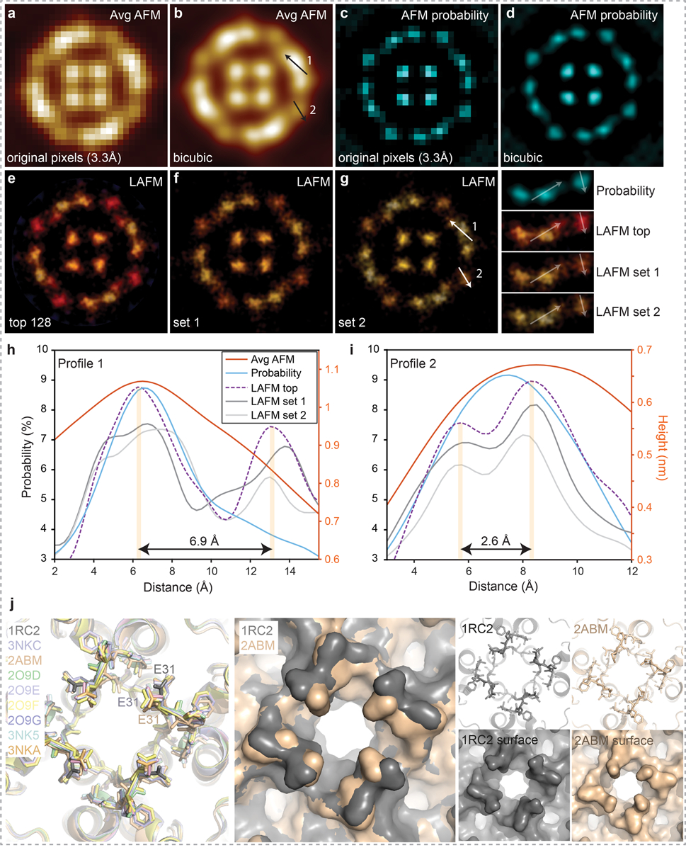
Average AFM images (a) at original pixel sampling of 3.3Å/p and (b) after bicubic interpolation to 0.5Å/p. Peak probability maps20 calculated (c) at original pixel sampling of 3.3Å/p and (d) after bicubic interpolation to 0.5Å/p (n=128 for average height and probability maps). LAFM probability maps calculated at 0.5Å/p with 1.4Å gaussian peaking probability distribution using (e) 128 AqpZ particles with highest correlation to the average map or using (f) and (g) two randomly generated independent 128 particle sets from a set of 256 to create two independent half-maps. Line profiles along (h) arrow 1, and (i) arrow 2 in b) and g) measuring height (for average AFM images) and probability across structural features in the average AFM, probability and LAFM probability maps. Line profiles show that features in the 2 line profiles are consistently resolved near and below the highest theoretical resolution based on the discrete sampling of a single image (raw data Nyquist frequency is 1/(6.6Å)). j) Left: Alignment of the 9 available AqpZ X-ray structures. The structures can be grouped with respect to the side chain orientation of E31 in the a-loop. Middle: Surface representation overlay of 1RC2 and 2ABM highlighting how the different E31 rotamers alter the surface structure. Right: representative structures (top) and surface representations (bottom) of 1RC2, and 2ABM. The 2ABM structure features an E31 conformation that fits closely the reconstructed LAFM map (panel g) and Figure 2a,b in the main manuscript), suggesting that in membrane, physiological buffer and room temperature E31 is in a conformation similar to the 2ABM structure.
Extended Data Figure 7|. Localization AFM (LAFM) map resolution and quality assessment.
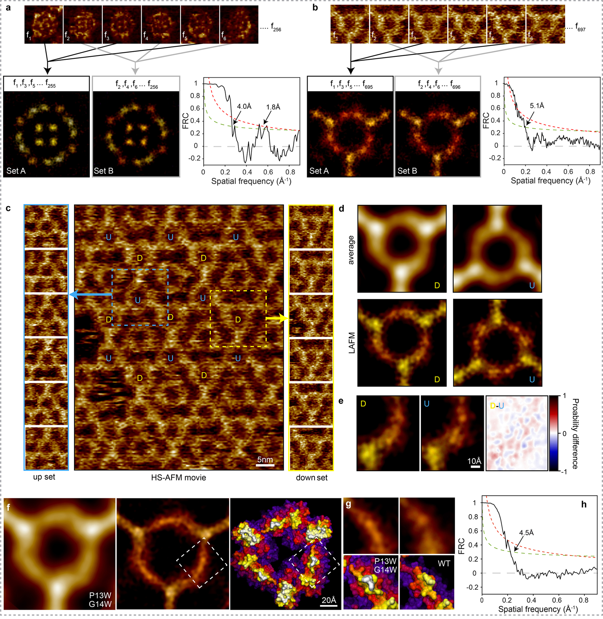
AFM Image frames of AqpZ (a) and A5 (b) are alternately extracted into two separate image sets (Set A and Set B). The localization AFM algorithm is then applied to each image set to produce two independent LAFM half-maps of AqpZ (left) and A5 (right). Fourier Ring Correlation (FRC) analysis of the LAFM half-maps is then used for quantification of the power as a function of the spatial resolution in the AqpZ dataset (left) and A5 (right). Dashed and dotted lines show the 1/2-bit and 3σ criteria respectively. c) Image from a HS-AFM movie of A5 in a p6 lattice (center) showing that the A5 lattice contains trimers of two fixed orientations labeled U and D. The two A5 trimer types U and D are scanned with different relative orientation with respect to the HS-AFM fast-scan axis. Extracted images of the trimers in each of the two orientations are shown either side for set U (up; left) and set D (down; right). d) Average AFM and LAFM maps filtered to 5Å of A5 trimers in the U (n = 700) and D (n = 697) orientations. e) Structural comparison between LAFM maps obtained from the independent differently orientated A5 and the probability difference map (Image U has been rotated 180o to allow direct comparison). f) Analysis of A5 P13W-G14W mutant (data acquisition: A5 P13W-G14W on a DOPC/DOPS (1/1) bilayer imaged by HS-AFM in amplitude modulation mode: Scan speed: 1 frame/s, scan area: 120nm, image size: 300pixel, pixel sampling: 4.0Å/p). Average AFM map (left), LAFM map (middle; pixel sampling: 0.5Å/p, number of particles: n = 300, filtered to 4.5Å) and surface representations of a A5 P13W-G14W structural model. g) Detail views of the LAFM maps (top), and structures (bottom; MD-refined structural model of A5 P13W-G14W and X-ray structure of A5). The mutations appear to induce conformational rearrangements in the N-terminal region (residues 1 to15), with an increased height and peaking-probability at positions 13–14 in the LAFM map. h) FRC analysis of the LAFM map.
Extended Data Figure 8|. Extracellular sidedness assignment of CLC-ec1.
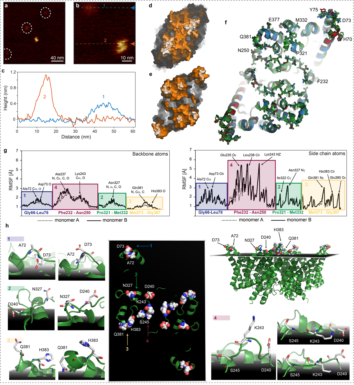
a) and b) HS-AFM movie frames of CLC-ec1 in a POPE:POPG (ratio of 2:1 (w:w)) bilayer: Molecules protruding just little and S-shaped molecules protruding further from the membrane were detected. c) Section analysis of the two molecules shown in (b): one molecular species protrudes only ~4Å from the bilayer, while the S-shaped representation of the CLC-ec1 protrudes ~11Å from the membrane surface. Surface representations of the (d) intracellular and (e) extracellular faces of the X-ray structure (PDB 1OTS): Based on the structural comparison, we assigned the S-shaped CLC-ec1 HS-AFM topography to the extracellular face. Only the S-shaped, extracellular face, molecules were integrated into the LAFM analysis. f) Alignment of CLC-ec1 the X-Ray structures (PDB: 1OTS, 2FEE, 2H2P, 3DET, 2HTK, 4KKB) exhibiting essentially identical conformations leading to the suggestion that the transport mechanism only implicated minor side-chain motion. NMR, computational and biochemical studies have suggested larger-scale movements of helices N39, O38 and B37 in transport. Protruding residues detectable by LAFM are shown in sticks and are labeled. g) Root mean square fluctuations (RMSFs) of the backbone (left) and the side chain (right) atoms of membrane protruding extracellular CLC-ec1 residues from the analysis of MD trajectories at pH 7. The colored blocks demarcate the groups of residues attributed to the four major LAFM and MD population map peaks, and the key residues are labeled. h) Key residues contributing to the peak observations in LAFM maps in the PDB 1OTS structure (middle and top right panels). The black shadowed plane illustrates the average position of the lipid phosphate atoms throughout the MD trajectories and thus represents the membrane level. Surrounding images (labeled 1 to 4) show representative snapshots from MD simulations highlighting re-orientations / fluctuations of the sidechains of the residues contributing to the LAFM-detected peaks.
Extended Data Figure 9|. Analysis of the influence of 2D-Gaussian radius to the peaking events and data pre-filtering on LAFM map reconstruction.
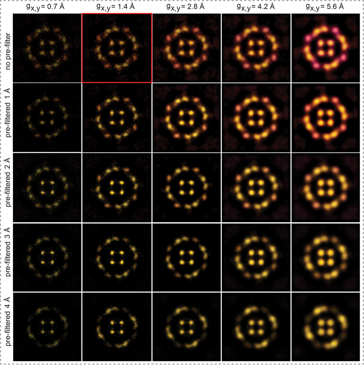
Horizontal panels show reconstructed AqpZ LAFM maps of peaking detections with varying 2D Gaussian radii of 0.7Å, 1.4Å, 2.8Å, 4.2Å and 5.6Å (without any pre-processing Gaussian filtering). The vertical panels show reconstructed AqpZ LAFM maps of images pre-processed with varying Gaussian filters of 0Å, 1Å, 2Å, 3Å and 4Å, while varying the peaking detection 2D Gaussian radius. The comparison shows that applying a filter to the data before applying the LAFM method results in a loss of information, particularly from features that are smaller or of lower height. Whereas increasing the 2D Gaussian radius applied to each localization during the LAFM method results in a loss of lateral resolution in the reconstructed LAFM map. Highlighted in red: Our standard method for constructing LAFM maps using no pre-filtering and a peaking detection 2D Gaussian of 1.4Å, approximating the solvent accessible surface of atoms.
Table 1|.
Set of available PDB structures of CLC-ec1 at various conditions. The RMSD values are calculated for backbone atoms with respect to the PDB 1OTS structure as reference.
| PDB ID | PH | Mutations | Ions | BB RMSD (Å) |
|---|---|---|---|---|
| 1OTS | 9.5 | NaCI | reference | |
| 1KPK | 8.5 | Na2SO4 / Li2SO4 | 0.785 | |
| 1KPL* | 4.6 | M26L/C264V | Na2SO4 / Li2SO4 | 1.169 |
| 1OTT | 9.5 | E148A | NaCI | 0.465 |
| 1OTU | 9.5 | E148Q | NaCI | 0.589 |
| 2EXY | 8.5 | E148Q | TART | 0.646 |
| 2EZ0 | 9.5 | S107A/E148Q/Y445A | NaBr | 0.722 |
| 2FEC | 7.5 | E203Q | NaBr | 0.425 |
| 2FED | 7.5 | E203Q | NaCI | 0.427 |
| 2FEE | 7.5 | NaBr | 0.362 | |
| 2H2P | 7.5 | KSCN | 0.515 | |
| 2H2S | 7.5 | E148A | KSeCN | 0.491 |
| 2HLF | 9.5 | Y445E | NaBr | 0.378 |
| 2HT2 | 8.5 | Y445H | TART | 0.654 |
| 2HT3 | 7.5 | Y445L | TART | 0.581 |
| 2HT4 | 8.0 | Y445W | NaBr | 0.533 |
| 2HTK | 8.5 | Y445A | TART | 0.378 |
| 2R9H | 9.5 | Q207C | NaCI / TART | 0.558 |
| 3DET | 5.5 | E148A / Y445A | KCI | 0.415 |
| 3EJY | 9.5 | NaBr | 0.425 | |
| 3EJZ | 8.5 | E203V | NaBr | 0.426 |
| 3NMO† | 9.5 | LiNO3 | 0.565 | |
| 4ENE | 8.5 | CaCI2 | 0.442 | |
| 4FTP | 9.5 | E202Y | 0.877 | |
| 4KJP | 9.5 | 0.412 | ||
| 4KK5 | 9.0 | NaF / NaBr | 0.282 | |
| 4KK8 | 8.5 | E148Q | NaF | 0.422 |
| 4KKB | 7.0 | E148A | NaF / NaBr | 0.454 |
| 4KKC | 9.0 | E148A | NaBr | 0.679 |
| 5HD8 | 9.0 | D417C | TART | 0.597 |
Denotes a low-pH structure of CLC from Salmonella typhimurium.
Denotes structures of monomers. All CLC X-ray structures exhibited essentially identical conformations. However, NMR, computational and biochemical studies have suggested larger-scale movements. A recent X-ray structure of a ClC-ec1 triple mutant (E148Q/E203Q/E113Q) that mimics the protonation of essential glutamates at low pH, reports global conformational changes that lead to opening of the extracellular permeation pathway.45 Thus, under the assumption that the displacements of surface features are signatures of movements in the underlying helices, our LAFM maps suggest motions that could result in changes in the region of the extracellular gate.
Supplementary Material
Acknowledgements:
This work was supported by the grant NIH DP1AT010874 (to S.S). We thank Dr. Asghar Razavi for his help with the initial stages of the MD simulation analysis and insightful discussions. The computational work was performed using resources of the Oak Ridge Leadership Computing Facility (allocation BIP109 and Director’s Discretionary) at the Oak Ridge National Laboratory, which is a DOE Office of Science User Facility supported under Contract DE-AC05–00OR22725, the resources and support provided at the RPI Artificial Intelligence Multiprocessing Optimized System (AiMOS) system accessed through an award from the COVID-19 HPC Consortium (https://covid19-hpc-consortium.org/), and the computational resources of the David A. Cofrin Center for Biomedical Information in Institute for Computational Biomedicine at Weill Cornell Medical College. Support from the 1923 Fund is gratefully acknowledged.
Footnotes
Competing interests:
The authors declare no competing interests.
Supplementary information:
The online version (https://doi.org/10.1038/s41586–021-03551-x) contains supplementary material available at: https://www.nature.com/articles/s41586–021-03551-x#Sec26.
Peer review information:
Nature thanks the anonymous reviewer(s) for their contribution to the peer review of this work.
Reprints and permissions information:
Reprints and permissions information is available at http://www.nature.com/reprints.
Code availability
The custom-written script implemented in ImageJ to create LAFM maps from a stack of aligned and expanded images is available in the supporting information. MATLAB codes used in 2D and 3D LAFM simulations are also available in the supporting information.
Data availability
The data sets generated during and/or analysed during the current study are available from the corresponding author on reasonable request.
References:
- 1.Binnig G, Quate CF & Gerber C Atomic Force Microscope. Phys. Rev. Lett. 56, 930–933 (1986). [DOI] [PubMed] [Google Scholar]
- 2.Heath GR & Scheuring S Advances in high-speed atomic force microscopy (HS-AFM) reveal dynamics of transmembrane channels and transporters. Curr. Opin. Struct. Biol. 57, 93–102 (2019). [DOI] [PMC free article] [PubMed] [Google Scholar]
- 3.Betzig E et al. Imaging intracellular fluorescent proteins at nanometer resolution. Science 313, 1642–5 (2006). [DOI] [PubMed] [Google Scholar]
- 4.Lin YC et al. Force-induced conformational changes in PIEZO1. Nature 573, 230–234 (2019). [DOI] [PMC free article] [PubMed] [Google Scholar]
- 5.Ando T et al. A high-speed atomic force microscope for studying biological macromolecules. Proc. Natl. Acad. Sci. U. S. A. 98, 12468–12472 (2001). [DOI] [PMC free article] [PubMed] [Google Scholar]
- 6.Kodera N, Yamamoto D, Ishikawa R & Ando T Video imaging of walking myosin V by high-speed atomic force microscopy. Nature 468, 72–76 (2010). [DOI] [PubMed] [Google Scholar]
- 7.Preiner J et al. High-Speed AFM Images of Thermal Motion Provide Stiffness Map of Interfacial Membrane Protein Moieties. Nano Lett. 15, 759–763 (2015). [DOI] [PMC free article] [PubMed] [Google Scholar]
- 8.Ruan Y et al. Structural titration of receptor ion channel GLIC gating by HS-AFM. Proc. Natl. Acad. Sci. 115, 10333–10338 (2018). [DOI] [PMC free article] [PubMed] [Google Scholar]
- 9.Heath GR & Scheuring S High-speed AFM height spectroscopy reveals μs-dynamics of unlabeled biomolecules. Nat. Commun. 9, 4983 (2018). [DOI] [PMC free article] [PubMed] [Google Scholar]
- 10.Nievergelt AP, Banterle N, Andany SH, Gönczy P & Fantner GE High-speed photothermal off-resonance atomic force microscopy reveals assembly routes of centriolar scaffold protein SAS-6. Nat. Nanotechnol. 13, 696–701 (2018). [DOI] [PubMed] [Google Scholar]
- 11.Eeftens JM et al. Condensin Smc2-Smc4 Dimers Are Flexible and Dynamic. Cell Rep. 14, 1813–1818 (2016). [DOI] [PMC free article] [PubMed] [Google Scholar]
- 12.Shibata M et al. Oligomeric states of microbial rhodopsins determined by high-speed atomic force microscopy and circular dichroic spectroscopy. Sci. Rep. 8, 8262 (2018). [DOI] [PMC free article] [PubMed] [Google Scholar]
- 13.Nasrallah H et al. Imaging artificial membranes using high-speed atomic force microscopy. in Methods in Molecular Biology 1886, 45–59 (2019). [DOI] [PubMed] [Google Scholar]
- 14.Viani MB et al. Fast imaging and fast force spectroscopy of single biopolymers with a new atomic force microscope designed for small cantilevers. Rev. Sci. Instrum. 70, 4300–4303 (1999). [Google Scholar]
- 15.Kodera N, Yamashita H & Ando T Active damping of the scanner for high-speed atomic force microscopy. Rev. Sci. Instrum. 76, 053708 (2005). [Google Scholar]
- 16.Kodera N, Sakashita M & Ando T Dynamic proportional-integral-differential controller for high-speed atomic force microscopy. Rev. Sci. Instrum. 77, 83704 (2006). [Google Scholar]
- 17.Shibata M et al. Real-space and real-time dynamics of CRISPR-Cas9 visualized by high-speed atomic force microscopy. Nat. Commun 8, 1430 (2017). [DOI] [PMC free article] [PubMed] [Google Scholar]
- 18.Gan Y Atomic and subnanometer resolution in ambient conditions by atomic force microscopy. Surf. Sci. Rep. 64, 99–121 (2009). [Google Scholar]
- 19.Müller DJ, Schabert FA, Büldt G & Engel A Imaging purple membranes in aqueous solutions at sub-nanometer resolution by atomic force microscopy. Biophys. J. 68, 1681–1686 (1995). [DOI] [PMC free article] [PubMed] [Google Scholar]
- 20.Scheuring S et al. High resolution AFM topographs of the Escherichia coli water channel aquaporin Z. EMBO J. 18, 4981–4987 (1999). [DOI] [PMC free article] [PubMed] [Google Scholar]
- 21.Fechner P et al. Structural Information, Resolution, and Noise in High-Resolution Atomic Force Microscopy Topographs. Biophys. J. 96, 3822–3831 (2009). [DOI] [PMC free article] [PubMed] [Google Scholar]
- 22.Markiewicz P & Goh MC Atomic Force Microscopy Probe Tip Visualization and Improvement of Images Using a Simple Deconvolution Procedure. Langmuir 10, 5–7 (1994). [Google Scholar]
- 23.Bukharaev AA, Bukharaev AA, Berdunov NV, Ovchinnikov DV & Salikhov KM Three-Dimensional Probe and Surface Reconstruction for Atomic Force Microscopy Using a Deconvolution Algorithm. eCM J. 12, 225 (1998). [Google Scholar]
- 24.Rust MJ, Bates M & Zhuang X Sub-diffraction-limit imaging by stochastic optical reconstruction microscopy (STORM). Nat. Methods 3, 793–796 (2006). [DOI] [PMC free article] [PubMed] [Google Scholar]
- 25.Small A & Stahlheber S Fluorophore localization algorithms for super-resolution microscopy. Nat. Methods 11, 267–279 (2014). [DOI] [PubMed] [Google Scholar]
- 26.Nieuwenhuizen RPJ et al. Measuring image resolution in optical nanoscopy. Nat. Methods 10, 557–562 (2013). [DOI] [PMC free article] [PubMed] [Google Scholar]
- 27.Scheuring S, Müller D, Stahlberg H, Engel H-A & Engel A Sampling the conformational space of membrane protein surfaces with the AFM. Eur. Biophys. J. 31, 172–178 (2002). [DOI] [PubMed] [Google Scholar]
- 28.Miyagi A, Chipot C, Rangl M & Scheuring S High-speed atomic force microscopy showsthat annexin V stabilizes membranes on the second timescale. Nat. Nanotechnol. 11, 783–790 (2016). [DOI] [PubMed] [Google Scholar]
- 29.Saxton WO & Baumeister W The correlation averaging of a regularly arranged bacterial cell envelope protein. J. Microsc. 127, 127–138 (1982). [DOI] [PubMed] [Google Scholar]
- 30.Accardi A & Miller C Secondary active transport mediated by a prokaryotic homologue of ClC Cl- channels. Nature 427, 803–807 (2004). [DOI] [PubMed] [Google Scholar]
- 31.Dutzler R, Campbell EB & MacKinnon R Gating the selectivity filter in ClC chloride channels. Science (80-. ). 300, 108–112 (2003). [DOI] [PubMed] [Google Scholar]
- 32.Jentsch TJ & Pusch M CLC Chloride Channels and Transporters: Structure, Function, Physiology, and Disease. Physiol. Rev. 98, 1493–1590 (2018). [DOI] [PubMed] [Google Scholar]
- 33.Accardi A et al. Separate ion pathways in a Cl-/H+ exchanger. J. Gen. Physiol. 126, 563–70 (2005). [DOI] [PMC free article] [PubMed] [Google Scholar]
- 34.Dutzler R, Campbell EB, Cadene M, Chait BT & MacKinnon R X-ray structure of a ClC chloride channel at 3.0 Å reveals the molecular basis of anion selectivity. Nature 415, 287–294 (2002). [DOI] [PubMed] [Google Scholar]
- 35.Abraham SJ et al. 13C NMR detects conformational change in the 100-kD membrane transporter ClC-ec1. J. Biomol. NMR 61, 209–26 (2015). [DOI] [PMC free article] [PubMed] [Google Scholar]
- 36.Khantwal CM et al. Revealing an outward-facing open conformational state in a CLC CL-/H+ exchange transporter. Elife 5, (2016). [DOI] [PMC free article] [PubMed] [Google Scholar]
- 37.Miloshevsky GV, Hassanein A & Jordan PC Antiport mechanism for Cl(−)/H(+) in ClC-ec1 from normal-mode analysis. Biophys. J. 98, 999–1008 (2010). [DOI] [PMC free article] [PubMed] [Google Scholar]
- 38.Basilio D, Noack K, Picollo A & Accardi A Conformational changes required for H+/Cl− exchange mediated by a CLC transporter. Nat. Struct. Mol. Biol. 21, 456–463 (2014). [DOI] [PMC free article] [PubMed] [Google Scholar]
- 39.Osteen JD & Mindell JA Insights into the ClC-4 transport mechanism from studies of Zn2+ inhibition. Biophys. J. 95, 4668–75 (2008). [DOI] [PMC free article] [PubMed] [Google Scholar]
- 40.Reyes N, Ginter C & Boudker O Transport mechanism of a bacterial homologue of glutamate transporters. Nature 462, 880–885 (2009). [DOI] [PMC free article] [PubMed] [Google Scholar]
- 41.Ruan Y et al. Direct visualization of glutamate transporter elevator mechanism by high-speed AFM. Proc. Natl. Acad. Sci. U. S. A. 114, 1584–1588 (2017). [DOI] [PMC free article] [PubMed] [Google Scholar]
- 42.Krishnamurthy H & Gouaux E X-ray structures of LeuT in substrate-free outward-open and apo inward-open states. Nature 481, 469–474 (2012). [DOI] [PMC free article] [PubMed] [Google Scholar]
- 43.Hofmann S et al. Conformation space of a heterodimeric ABC exporter under turnover conditions. Nature 571, 580–583 (2019). [DOI] [PMC free article] [PubMed] [Google Scholar]
- 44.Accardi A, Kolmakova-Partensky L, Williams C & Miller C Ionic Currents Mediated by a Prokaryotic Homologue of CLC Cl Channels. J. Gen. Physiol. J. Gen. Physiol 123, 109–119 (2004). [DOI] [PMC free article] [PubMed] [Google Scholar]
- 45.Chavan TS et al. A CLC-ec1 mutant reveals global conformational change and suggests a unifying mechanism for the Cl–/H+ transport cycle. Elife 9, (2020). [DOI] [PMC free article] [PubMed] [Google Scholar]
- 46.Miyagi A & Scheuring S A novel phase-shift-based amplitude detector for a high-speed atomic force microscope. Rev. Sci. Instrum. 89, 083704 (2018). [DOI] [PubMed] [Google Scholar]
- 47.Marchesi A et al. An iris diaphragm mechanism to gate a cyclic nucleotide-gated ion channel. Nat. Commun 9, (2018). [DOI] [PMC free article] [PubMed] [Google Scholar]
- 48.Chadda R et al. The dimerization equilibrium of a ClC Cl−/H+ antiporter in lipid bilayers. Elife 5, (2016). [DOI] [PMC free article] [PubMed] [Google Scholar]
- 49.Burger W & Burge MJ Digital image processing: an algorithmic introduction using Java. (Springer, 2016). [Google Scholar]
- 50.Fukuma T & Garcia R Atomic- and Molecular-Resolution Mapping of Solid–Liquid Interfaces by 3D Atomic Force Microscopy. ACS Nano 12, 11785–11797 (2018). [DOI] [PubMed] [Google Scholar]
- 51.Lee B & Richards FM The interpretation of protein structures: Estimation of static accessibility. J. Mol. Biol. 55, 379–490 (1971). [DOI] [PubMed] [Google Scholar]
- 52.Scheres SHW Semi-automated selection of cryo-EM particles in RELION-1.3. J. Struct. Biol. 189, 114–122 (2015). [DOI] [PMC free article] [PubMed] [Google Scholar]
- 53.Bustamante C & Keller D Scanning Force Microscopy in Biology. Phys. Today 48, 32–38 (1995). [Google Scholar]
- 54.Olsson MHM, Sondergaard CR, Rostkowski M & Jensen JH PROPKA3: Consistent Treatment of Internal and Surface Residues in Empirical pKa Predictions. J. Chem. Theory Comput. 7, 525–537 (2011). [DOI] [PubMed] [Google Scholar]
- 55.Lomize MA, Lomize AL, Pogozheva ID & Mosberg HI OPM: orientations of proteins in membranes database. Bioinformatics 22, 623–625 (2006). [DOI] [PubMed] [Google Scholar]
- 56.Jo S, Lim JB, Klauda JB & Im W CHARMM-GUI Membrane Builder for Mixed Bilayers and Its Application to Yeast Membranes. Biophys. J. 97, 50–58 (2009). [DOI] [PMC free article] [PubMed] [Google Scholar]
- 57.Phillips JC et al. Scalable molecular dynamics with NAMD. J. Comput. Chem. 26, 1781–1802 (2005). [DOI] [PMC free article] [PubMed] [Google Scholar]
- 58.Khelashvili G et al. Spontaneous Inward Opening of the Dopamine Transporter Is Triggered by PIP-Regulated Dynamics of the N-Terminus. ACS Chem Neurosci 6, 1825–1837 (2015). [DOI] [PMC free article] [PubMed] [Google Scholar]
- 59.Essmann U et al. A Smooth Particle Mesh Ewald Method. J. Chem. Phys. 103, 8577–8593 (1995). [Google Scholar]
- 60.Evans DJ & Holian BL The Nose-Hoover Thermostat. J. Chem. Phys. 83, 4069–4074 (1985). [Google Scholar]
- 61.Harvey M, Giupponi G & De Fabritiis G ACEMD: Accelerated molecular dynamics simulations in the microseconds timescale. J. Chem. Theory Comput. 5, 1632–1639 (2009). [DOI] [PubMed] [Google Scholar]
- 62.Van Der Spoel D et al. GROMACS: Fast, flexible, and free. Journal of Computational Chemistry 26, 1701–1718 (2005). [DOI] [PubMed] [Google Scholar]
- 63.Duan Y et al. A Point-Charge Force Field for Molecular Mechanics Simulations of Proteins Based on Condensed-Phase Quantum Mechanical Calculations. J. Comput. Chem. 24, 1999–2012 (2003). [DOI] [PubMed] [Google Scholar]
- 64.Emsley P & Cowtan K Coot: Model-building tools for molecular graphics. Acta Crystallogr. Sect. D Biol. Crystallogr. 60, 2126–2132 (2004). [DOI] [PubMed] [Google Scholar]
- 65.Jorgensen WL, Chandrasekhar J, Madura JD, Impey RW & Klein ML Comparison of simple potential functions for simulating liquid water. J. Chem. Phys. 79, 926–935 (1983). [Google Scholar]
- 66.Bussi G, Donadio D & Parrinello M Canonical sampling through velocity rescaling. J. Chem. Phys. 126, :014101 (2007). [DOI] [PubMed] [Google Scholar]
Associated Data
This section collects any data citations, data availability statements, or supplementary materials included in this article.
Supplementary Materials
Data Availability Statement
The data sets generated during and/or analysed during the current study are available from the corresponding author on reasonable request.


