Abstract
The pericardium of the human heart has received increased attention in recent times due to interest in the epicardial approach for cardiac interventions to treat cardiac arrhythmias refractory to conventional endocardial approaches. To support further clinical application of this technique, it is fundamental to appreciate the living anatomy of the pericardial space, as well as its relationships to the surrounding structures. The anatomy of the pericardial space, however, is extremely difficult regions to visualize. This is due to its complex three dimensionality, and the ‘potential’ nature of the space, which becomes obvious only when there is collection of pericardial fluid. This ‘potential’ space, which is bounded by the epicardium and pericardium, can now be visualized by special techniques as we now report, permitting appreciation of its living morphology. Current sources of knowledge are limited to the dissection images, surgical images, and/or illustrations which are not necessarily precise or sufficient to provide relevant comprehensive anatomical knowledge to those undertaking the epicardial approach. We demonstrate, for the first time, the three-dimensional living anatomy of the pericardial space relative to its surrounding structures. We also provide correlative anatomy of the left sternocostal triangle as a common site for subxiphoid access. We anticipate our report serving as a tool for education of imaging and interventional specialists.
Keywords: cardiac anatomy, computed tomography, pericardial recess, pericardial sinus, pericardial space
Condensed abstract:
The epicardial approach has received increased attention in clinical electrophysiology. To further expand its clinical application, precise three-dimensional appreciation of the living anatomy of the pericardial space and its relationships to surrounding structures is crucial. However, it remains difficult to visualize the complex three-dimensionality of the pericardial space, as it is typically obvious only in the setting of pericardial effusions. The space, furthermore, is easily distorted once the pericardium is opened. In this review, the living anatomy of the pericardial space and its surrounding structures is demonstrated using three-dimensional images and printed models.
Introduction
In 1996, Sosa et al. first introduced the epicardial approach for treatment of refractory ventricular tachycardia (1). With further accumulated experiences (2, 3), the technique is now well established (4–7). Currently, the epicardial approach is applied with a wide range of indications (8, 9), not only for treating refractory ventricular arrhythmias, but also for supraventricular arrhythmias (10, 11) with various epicardial devices used to support the ablation procedure (12–16). The epicardial approach is also used for structural interventions, such as percutaneous closure of the left atrial appendage (17). It follows that precise appreciation of the living anatomy of the space is increasingly important to ensure procedural success without compromising safety. Three-dimensional appreciation of the pericardial anatomy, however, is extremely difficult. This is because the pericardial space is no more than the virtual space between the epicardium and pericardium, a fact which limits the utility of most available anatomic guides. Thus far, learning sources of three-dimensional pericardial anatomy have been limited to the dissection images, surgical images, and/or illustrations (Figure 1) (18–26). Dissection cannot visualize the space without distorting the anatomy of the pericardium. The majority of electrophysiologists, furthermore, do not have the opportunity to be involved in anatomic dissections. Two-dimensional illustrations do not provide precise and comprehensive information of the complex anatomy. Although several attempts have been made, based on datasets obtained from computed tomography and/or magnetic resonance imaging, to clarify the living anatomy of the pericardial space and reflections (19, 27–29), accurate visualization of the extent of the space remains elusive. With this in mind, recently we published our first three-dimensional imaging of the space (30) based on the findings in the setting of cardiac tamponade. Using a similar approach, in this review we now provide a detailed description and illustration of the three-dimensional living anatomy of the pericardial space, hoping to enhance understanding of the clinical anatomy, thus supporting safe epicardial intervention. This study was approved by the UCLA Institutional Review Board.
Figure 1. Dissected anatomy of the pericardial space.
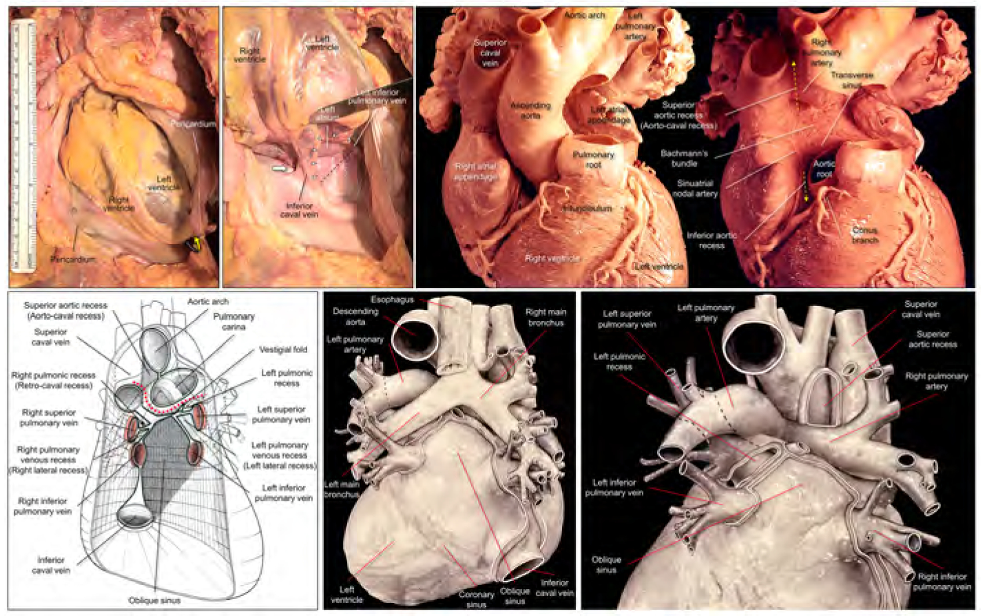
Left upper panels show dissection images to show the entrance to the oblique sinus. The apex is raised up (yellow curved arrow) and inverted in the right panel. The entrance of the oblique sinus (white arrowheads and black dashed line), demarcated by the inferior caval vein and the left inferior pulmonary vein is oblique to the vertical body axis. Because of the reflection between the inferior caval vein and the right inferior pulmonary vein, it is impossible to pass this region toward the left side to the oblique sinus (thick white arrow). Right upper panels show high-resolution photographs focusing on the structural anatomy surrounding the transverse sinus recorded by Dr. W.A. McAlpine.18 The pulmonary trunk has been removed in the left panel. Progressive dissection to remove the ascending aorta (right panel) clarifies the space corresponding to the transverse sinus viewed from the slight cranial direction. Refer to Figures 2 and 3. Lower panels are illustrations modified from the McAlpine collection,18 focusing on the pericardial anatomy. Note the oblique entrance of the oblique sinus visualized in the left and middle lower panels. Red dotted line indicates the transverse sinus. Note the hyparterial long left bronchus and eparterial short right bronchus in the middle lower panel (65). Posterior hilum at the roof of the left atrium and its relationship to the extra-pericardial right pulmonary artery can be appreciated in the right lower panel. Illustration courtesy UCLA Cardiac Arrhythmia Center, Wallace A. McAlpine MD collection, reproduced with permission.
Basic developmental aspects to understand postnatal pericardial anatomy
While detailed embryology is outside the scope of this review, the following points are essential knowledge for clinicians who are considering performing epicardial interventions (Figure 2).
Figure 2. Development and living anatomy of the pericardial space.
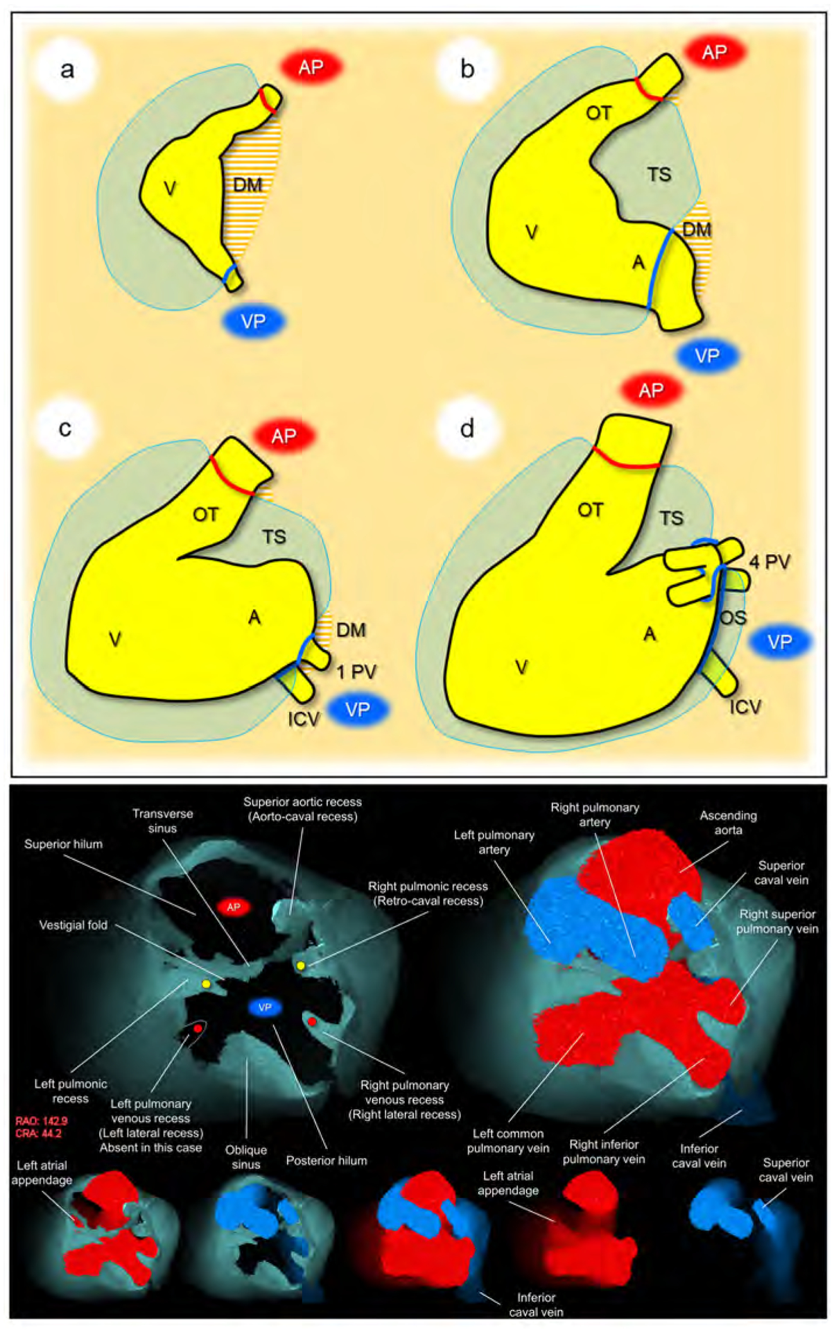
Developmental concepts of the pericardial space (upper panel). a. The heart tube is anchored to the body wall by both arterial and venous poles and dorsal mesocardium. b. The dissolution of the dorsal mesocardium creates the transverse sinus. c. Single pulmonary vein developed from the mesocardium at the venous pole. d. Superior expansion of the four pulmonary veins creates the deep oblique sinus. Lower panel. Basal superior views of the superior hilum and posterior hilum without heart (left) and with heart (right). Lower five images show the composite and component images viewed from the same direction to show the detailed anatomical information. Pericardial space is reconstructed as the solid structure. Yellow circles indicate bilateral pulmonic recess. Red circles indicate bilateral pulmonary venous recess, although it should be noted that this patient does not show a prominent left pulmonary venous recess due to the left common pulmonary vein. Note the symmetry in these recesses. Vestigial fold, between the transverse sinus and left pulmonic recess corresponds to the ligament of Marshall, subsequent to regression of the left superior caval vein. Refer to Supplementary movie 1. A, atrium; AP, arterial pole; CRA, cranial; DM, dorsal mesocardium; ICV, inferior caval vein; OS, oblique sinus; OT, outflow tract; PV, pulmonary vein; RAO, right anterior oblique; TS, transverse sinus; V, ventricle; VP, venous pole.
The arterial and venous poles during development correspond to two hilar ‘orifices’ of the heart surrounded by pericardial reflection in the postnatal heart (Figure 2a). These are the only sites that allow the mediastinum to communicate with the sub-epicardial layer of the heart, allowing the entrance of extracardiac nerves and vessels (31–33).
The involution of the dorsal mesocardium, other than at the arterial and venous poles (34–36), permits the communication dorsally between the right and left halves of the developing pericardial cavity (Figure 2b). This communication eventually becomes the transverse sinus.
When first formed, the pulmonary vein opens through a solitary orifice adjacent to the developing left atrioventricular junction (37, 38). It is the “migration” of the veins to the roof of the left atrium, with production of the eventual four orifices (Figure 2c), which creates the deep oblique sinus found in the postnatal heart (Figure 2d).
General anatomy of the pericardial space
Pericardium and epicardium
The normal pericardium is a sac that envelopes the heart, except at the two orifices, corresponding to the entrances and exits of the arterial trunks and veins surrounded by their pericardial reflections (Central illustration, Figure 2) (31). In other words, this sac is invaginated by the heart (22). Thus, the pericardial space allows the normal heart to move freely from its surrounding structures, including the trachea, esophagus, descending aorta, vertebra, lungs, and diaphragm. To ensure further free lifelong motion, the internal surface of this sac is composed of a double layered serous membrane, containing a small amount, usually less than 50 mL of serous fluid, which lubricates the surface of the heart (20). Thus, the serous component of the sac has visceral and parietal layer. The parietal layer lines the tough outer fibrous pericardium (25). Conventionally, the visceral layer of the serous coat is described as the epicardium. The term pericardium, therefore, can also be used to describe the combined serous and fibrous parietal layers (20). It is this double-layered pericardium (25) that is punctured during percutaneous access to the pericardial space to permit epicardial ablation and other interventions.
Central illustration. Living anatomy of the pericardial space.
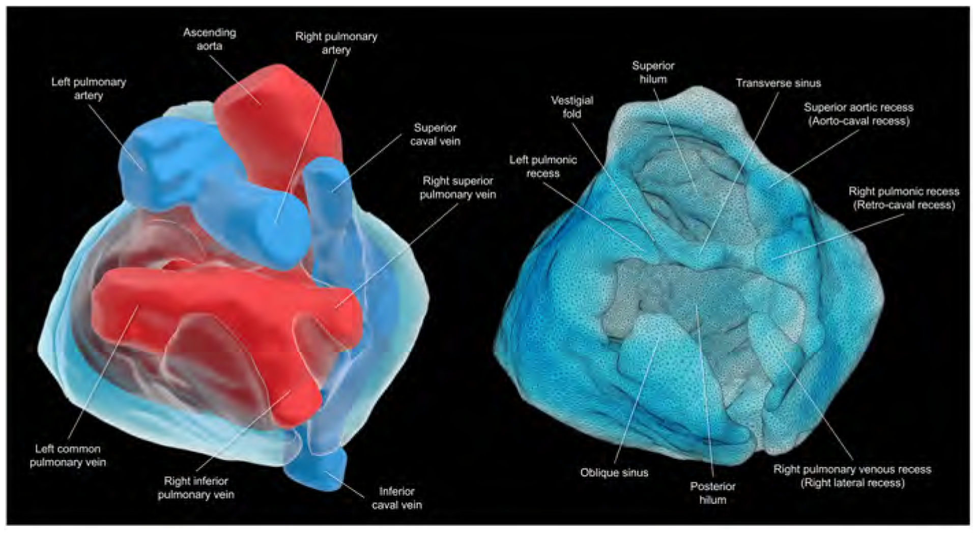
Views of the superior hilum and posterior hilum with (left) and without (right) heart. Pericardial space is reconstructed as the solid structure. The superior hilum involves the ascending aorta and pulmonary trunk. The posterior hilum involves pulmonary veins and caval veins, separated by the transverse sinus. Both hila, separated by the transverse sinus, are the only entry/exit for the extracardiac nerves and vessels. This patient does not show prominent left pulmonary venous recess due to the left common pulmonary vein.
Adipose tissue
Adipose tissue is only located underneath the epicardium and outside the fibrous pericardium. Accordingly, there is no adipose tissue within the pericardial space. The adipose layers are referred to as “epicardial fat/sub-epicardial fat”, and “mediastinal fat/pericardial fat”, respectively. The epicardial fat surrounds the epicardial myocardial surface. It contains coronary vessels, nerves, and the ganglionated plexus (22, 23). Although the distribution and thickness of the epicardial fat shows significant locational and individual variations (39, 40), it is commonly concentrated along the atrioventricular and interventricular grooves, with the coronary vessels embedded within it (22). As the distribution of epicardial fat may affect the efficacy and safety of epicardial catheter ablation procedures (22), and the epicardial fat can be the target of epicardial ablation to modify the ganglionated plexus located within the fat (41, 42), knowledge of its individual and three-dimensional distribution is significant in relation to the target region via preprocedural imaging (40, 43–45).
Living anatomy of the pericardial space
Using injection of contrast into the pericardium in a 38-year-old man with hypertrophic cardiomyopathy subsequent to an ablation, we performed image analyses using a commercially available workstation (Ziostation2 version 2.9.7.1; AMIN Co., Ltd., Tokyo, Japan; Ziosoft Inc., Tokyo, Japan).
The anterior, inferior, lateral, and apical regions of the space are easy to understand. In these regions, the space does no more than surround the heart, lacking any recesses or reflections. Hence, the reason the apical ventricle is relatively free to move, a feature easily confirmed during surgical procedures, dissection (Figure 1), and normal as well as pathological clinical observation such as electrical alternans (46). Entire epicardial surface of both ventricles and substantial part of epicardial surface of both atria that are not related to two orifices surrounded by the pericardial reflections can be readily approached during epicardial ablation. Reflecting the manner of its development (Figure 2), the anatomy is more complex in relation to the structures that develop in proximity to the superior arterial pole and posterior venous pole at the base of the heart. It is, therefore, important to focus on the complexities of anatomy found at the arterial and venous poles.
Pericardial reflections
The pericardial reflections represent the transitions between the visceral and parietal layers of the pericardium, in other words, between the epicardium and pericardium. They are located basally in relation to the arterial trunks and the systemic and pulmonary veins (Figures 1–3, Supplementary movies 1–4). They effectively produce two hilar orifices. The first is located superiorly, surrounding the pulmonary trunk and ascending aorta. The second is located posteriorly, surrounding the pulmonary and caval veins (31). These hilar orifices serve as a passageway for the extracardiac nerves and extracardiac vessels to enter into and exit from the sub-epicardial layer of the heart (31, 32, 47). In this regard, these two orifices face directly towards the extracardiac mediastinum. Pauza et al. termed these two orifices as the “hilum of the heart” (31). For convenience, we now describe each orifice of both arterial and venous poles as superior hilum and posterior hilum, respectively (Figure 2). To maintain the general position of the heart within the thorax, the outer fibrous pericardium is widely attached to the central tendon of the diaphragm inferiorly, and by the superior and inferior sternopericardial ligaments anteriorly. The heart is securely anchored to the posterior sternal surface by these latter structures (25).
Figure 3. Solid and double-layer reconstructions of the pericardial space.
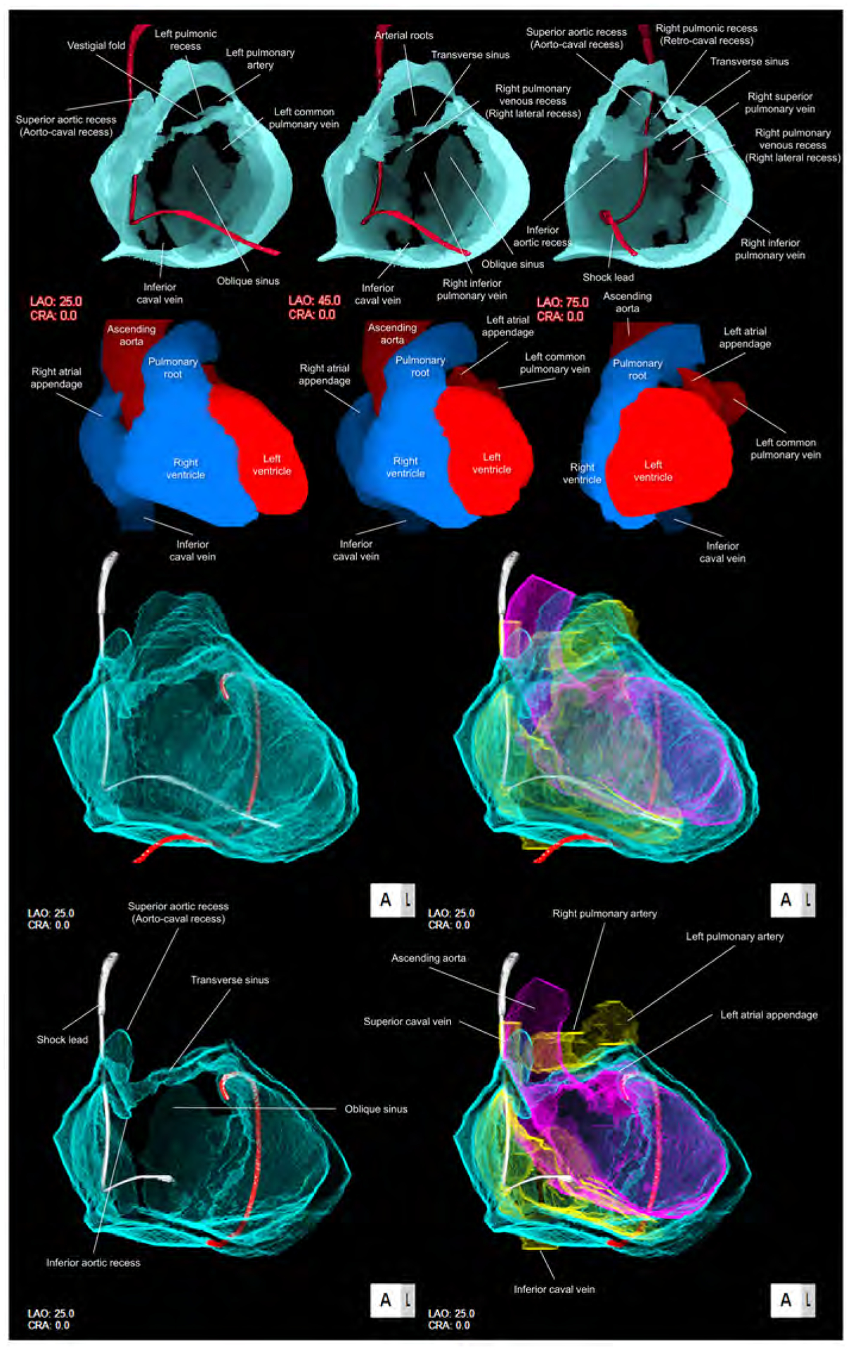
Upper panels are solid reconstructions of the pericardial space with corresponding cardiac chamber endocast images. Note that the course of the shock lead represents the location of the superior caval vein between the transverse sinus and right pulmonic recess. Also, the transverse sinus is continuous with superior and inferior aortic recesses. The narrowest diameter of the transverse sinus in this case is 1.4 × 1.8 mm. Refer to Supplementary movie 2. Oblique sinus is a tongue-like shaped blind end with its orifice demarcated by the inferior caval vein and the left inferior pulmonary vein. Lower panels are double-layer reconstruction of the pericardial space without (left panels) and with (right panels) heart shell. The right and left heart are colored in yellow and purple, respectively. Lower panels are sectioned to show the transverse sinus and oblique sinus in relation with cardiac chambers. Note the posterior course of the transverse sinus relative to the arterial roots. Oblique orifice of the oblique sinus is well observed in left lower panel. A drainage tube located adjacent to the left atrial appendage via the inferior course is reconstructed in red. Refer to Supplementary movies 3, 4 and 8. CRA, cranial; LAO, left anterior oblique.
Superior hilum and posterior hilum
The superior hilum corresponds to the arterial pole, which includes the intrapericardial ascending aorta and the pulmonary trunk. The posterior hilum corresponds to the venous pole, and involves the pulmonary and caval veins (Figures 2, 3) (30, 31). Both hila are adjacent during the developmental looping of the heart, but they do not communicate with each other, being separated by the transverse sinus. They persist, nonetheless, as the only routes for the extracardiac nerves and vessels to enter the epicardial layer of fat (48). The superior hilum is the gateway for the superficial cardiac plexus, whereas the posterior hilum provides the communication between the deep cardiac plexus with a complicated communication with ganglionated plexi of the heart (49, 50).
The shape of the posterior hilum is very complex compared with its superior counterpart, having several recesses (Figures 1–3, Supplementary movies 1–4). Each recess, nonetheless, is basically symmetrical (Figures 1, 2). The posterior hilum is demarcated by the transverse sinus supero-anteriorly, and the oblique sinus infero-posteriorly. The right and left pulmonic recesses are initially located between the superior caval veins and the superior pulmonary veins. As the left superior caval vein regresses, a fold is created between the left pulmonic recess and transverse sinus (Figures 1, 2). With attenuation of the venous structure, the fold, when vestigial, contains the ligament of Marshall (18, 25). The right pulmonic recess is also called retro-caval recess. The right and left pulmonary venous recesses, also known as the lateral recesses, are located between the superior and inferior pulmonary veins on each side, showing significant variations in their extent (21). These four basically symmetric recesses, along with the oblique and transverse sinuses, are key to forming the complex shape of the posterior hilum (Figures 1, 2). All of these sinuses and recesses are related to the left atrial roof, the left atrial posterior wall, and the pulmonary veins. They can, therefore, be used as epicardial sites of access to these structures. Comprehensive isolation of the pulmonary veins, nonetheless, is not feasible via this epicardial approach (13). This is because the posterior aspect of the pulmonary veins lacks pericardial reflections. Thus, epicardial ablation cannot be considered as the first choice to perform pulmonary venous isolation with a standard percutaneous approach. The only asymmetric structure in the posterior hilum is the reflection surrounding the inferior caval vein connecting to the reflection surrounding the right inferior pulmonary vein (Figures 1–3). This feature reflects the asymmetrical development of the sinus horns. Because of this reflection between the inferior caval vein and the right inferior pulmonary vein, it is not possible to move into the oblique sinus from the right posterior side of the inferior caval vein (Figures 1, 2). The roof of the left atrium, and the antrum of the pulmonary veins, is where the posterior hilum faces directly the mediastinum and the extra-pericardial right pulmonary artery (Figures 1, 2, Supplementary movie 5). Perforation of the left atrium corresponding to the posterior hilum, therefore, will not result in cardiac tamponade. Instead, it will create a mediastinal hematoma. In some patients, two adjacent reflections between the transverse sinus and oblique sinus can fuse to separate the posterior hilum, forming a partition between these sinuses. In these instances, the transverse sinus can be attached to the oblique sinus, even though they cannot communicate (18, 30). The shape of the hilum of the heart shows wide individual variations (51) reflecting the variations in the morphologies of the pericardial recesses and sinuses (18, 21).
Oblique sinus
The oblique sinus is located inferior to the posterior hilum, surrounded by the pulmonary veins and inferior caval vein. As the inferior caval vein is located much inferior to the left inferior pulmonary vein, the orifice of the sinus demarcated by these veins is easily observed in oblique fashion relative to the bodily vertical axis when lifting the cardiac apex (Figures 1, 3). Access to this orifice, therefore, is easier from the left inferolateral side rather than the right inferomedial side, as the mouth opens in the left inferolateral direction (Figures 1, 3). The oblique vein and ligament of the left atrium, also known as the vein and ligament of Marshall, are located infero-anterior to the orifice of the oblique sinus. These structures extend from the coronary sinus at its junction with the great cardiac vein, continuing into the vestigial fold between the left pulmonary veins and the left atrial appendage. The oblique sinus is the reverse U-shaped blind end, separated from the transverse sinus by the posterior hilum. The main target structures for epicardial ablation via the oblique sinus are the left atrial posterior wall and the pulmonary veins (52).
Transverse sinus
The transverse sinus connects the right and left pericardial sinuses posterior to the great arteries. Reflecting its development (Figure 2), the transverse sinus is located between the superior hilum and posterior hilum. During dissection, a probe can readily be passed through the transverse sinus, from the space around the left atrial appendage to the space between the ascending aorta and the superior caval vein (Figures 1–3). This should not be attempted during epicardial mapping for the purpose of moving a catheter across the heart, as it is easier, and much safer, to pass anteriorly to the pulmonary trunk and the infundibular portion of the right ventricular outflow tract. Clinically, guiding a catheter through the transverse sinus is challenging as the transverse sinus is not a simple conduit but takes a tightly curved course. The apex of the left atrial appendage is free within the left-sided entrance of the transverse sinus. The catheter can pass either inferiorly or superiorly to the left atrial appendage to access the transvers sinus. This is why external occlusion of the left atrial appendage is feasible (17). Posterior to the ascending aorta, the transverse sinus has superior and inferior extensions, known as the superior and inferior aortic recesses (Figures 1–4). The superior aortic recess is also called the aorto-caval recess. The potential targets accessible via this transverse sinus are the left atrial anterior wall, the left atrial appendage, the left ventricular summit, the vestigial fold containing the ligament of Marshall, the posterior to right side of the aortic root, including the left and non-coronary aortic sinuses, the anterior side of the superior caval vein, and the medial part of the right atrial appendage. Bachmann’s bundle, which runs in the antero-superior aspect of the left atrial anterior wall, could be accessed via the transverse sinus. As discussed above, however, this is not recommended (Figure 1). The inferior part of Bachmann’s bundle, the left atrial wall, is very thin at the region adjacent to the posterior half of the non-coronary aortic sinus and the posterior half of the left coronary aortic sinus (18). The sinuatrial nodal arteries, regardless of its left or right coronary arterial origin, is also close to the transverse sinus (Figure 1). Every epicardial intervention around the transverse sinus carries a risk of sinuatrial node infarction (18). Coronary angiography, therefore, is essential prior to considering intervention.
Figure 4. Living anatomy of the pericardial space and surrounding structures.
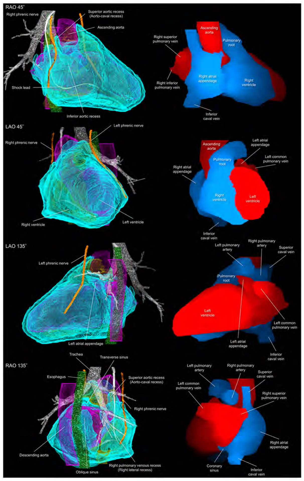
Pericardial anatomy with internal and external adjacent structures visualized in every 90° with corresponding cardiac chamber endocast images. In the left images, the right and left heart are colored in yellow and purple, respectively. The vertebral column and pleura are additionally reconstructed in the Supplementary movie 5. Refer to Figure 1. LAO, left anterior oblique; RAO, right anterior oblique.
Adjacent structures
In addition to appreciating the relationship between the pericardial space and the heart (Figures 2, 3, Supplementary movies 3, 4), understanding the anatomy of the adjacent structures is important. This is because the epicardial approach from the pericardial space has additional risks to these structures compared to an endocardial approach (53). The transverse sinus is close to the superiorly located epicardial right pulmonary artery and the left bronchus. The oblique sinus is adjacent to the posteriorly located esophagus, descending aorta, vertebra, and the intercostal arteries (Figures 1, 4). The phrenic nerves run downward on the fibrous pericardium anteriorly to the both pulmonary hila (42). The right phrenic nerve runs basally near the terminal crest. As the left ventricular apex directs in a leftward and anteriorly, the left phrenic nerve courses apically relative to its right counterpart, running on the left atrial appendage (54) and basal-mid lateral left ventricle (Figure 4). The relationship between these adjacent structures and cardiac chamber, however, can vary according to structural and postural changes involving the heart. This means that the target cardiac structure does not always precisely indicate the adjacent structure at risk. Especially when treating a patient with significant dilatation of chambers and/or rotation in cardiac positions, careful preprocedural evaluation of surrounding structural anatomy would be required. A substantial part of the lateral pericardium is close to the pleura (Supplementary movie 5). Endocardial, as well as epicardial intervention, potentially places these adjacent structures at risk (14–16, 53–55). The “potential space” of the pericardium can be used to prevent damage to these surrounding structures during endocardial ablation, such as protection using the balloon inserted in the oblique sinus (14, 15, 52).
Furthermore, Figure 5 demonstrates the relationship among the pericardium, parietal pleura, and mediastinal structures reconstructed from cardiac computed tomographic datasets obtained from a 35-year-old woman with pericardial effusion.
Figure 5. Virtual dissection images showing the relationship among the pericardium, parietal pleura, and mediastinal structures.
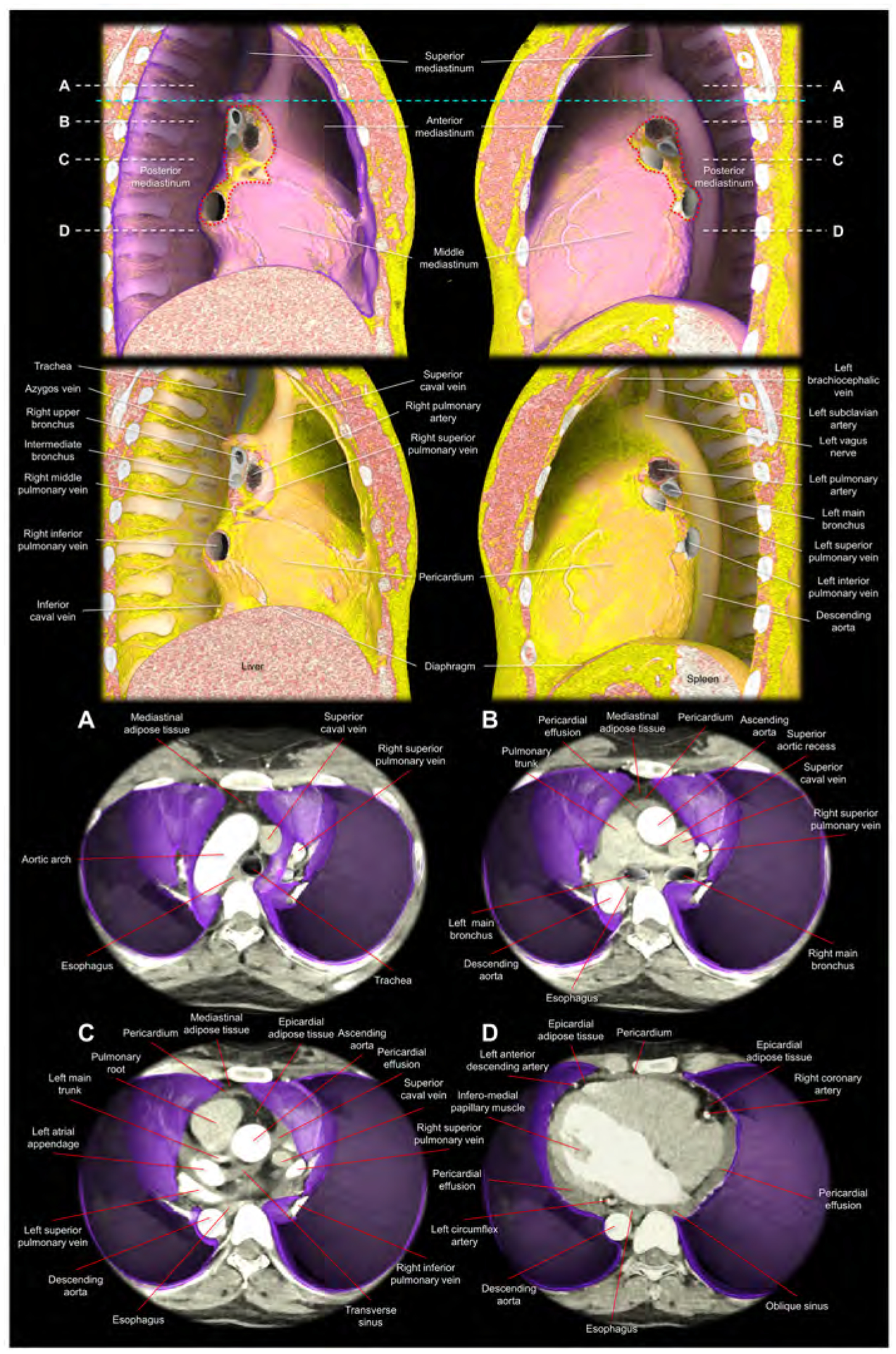
Images are reconstructed from the cardiac computed tomographic datasets obtained from a 35-year-old woman with pericardial effusion, which makes it easier to discern the pericardium corresponding to the outer margin of the pericardial effusion. The upper panels show the right and left lateral images of the thorax after virtual resection of the bilateral lungs. The purple region indicates the parietal pleura. The red dotted lines correspond to the estimated location of the pleural reflections surrounding bilateral pulmonary hila. Note the difference in the spatial relationship between the bronchus and pulmonary artery, when comparing the right and left pulmonary hila (65). The sky-blue dashed line corresponds to the horizontal plane sectioned at the height of the sternal angle used to define the superior mediastinum. The second upper panels show the additional virtual peeling off of the parietal pleura. The rich mediastinal adipose tissues located in the superior and anterior mediastinum are noted. Note the intercostal arteries, left vagus nerve, and the azygos vein overriding the right superior pulmonary vein, right pulmonary artery, and the right bronchus. Lower panels are virtual dissection images viewed from the superior direction after virtual resection of the bilateral lungs. Therefore, the bottom of the thorax corresponds to the diaphragmatic surface covered by the parietal pleura (purple). Panels A-D correspond to the planes A-D indicated in the upper panels (white dashed lines). Panel A shows the superior mediastinum, above the level of the anterior pericardial reflection. Thus, the adipose tissue anterior to the aortic arch is not the epicardial adipose tissue, but the mediastinal adipose tissue. Panel B shows the level just inferior to the superior margin of the anterior reflection of the pericardium. The adipose tissue anterior to the pericardium is the mediastinal adipose tissue. At the middle mediastinum, substantial part of the lateral pericardium is adjacent to the parietal pleura. Thus, the phrenic nerves, descending anterior to the both pulmonary hila, are sandwiched between the pericardium and medial part of the parietal pleura. Panel C shows the level of the transverse sinus. Rich epicardial adipose tissue, which is located interiorly to the pericardial space, can be observed. Panel D is the level of the infero-lateral papillary muscle of the left ventricle. Note the pericardial effusion filling postero-lateral pericardial space and the oblique sinus. From the pleural space, the pericardial space is accessible by penetrating the parietal pleura and the pericardium. Note the epicardial adipose tissue at the anterior interventricular groove and the atrioventricular grooves, which involve coronary arteries. Note the mediastinal adipose tissue of the anterior mediastinum behind the sternum becomes thinner in panel C compared to panel B, and it is almost undetectable in the panel D. The esophagus is distant from the left parietal pleura with the intervening of the descending aorta.
After coronary artery bypass grafting using median sternotomy, pericardial/epicardial adhesion develop predominantly beneath the incision scar which will make the epicardial approach via subxiphoid access fraught with added risks. If the patient underwent coronary angiography, this is readily detectable by the loss of pulsatile motion of the part of the conus branches and/or right ventricular branches. This finding indicates the adhesive fixation of the epicardial coronary artery to the underside of the anterior chest wall beneath the sternal wires (Supplementary Figure 1, Supplementary movies 6, 7). In our own practice we avoid percutaneous epicardial access following bypass surgery and instead opt for surgical hybrid procedures.
Living anatomy of the left sternocostal triangle
The left sternocostal triangle is an optimal window to enter the pericardial space, using either an anterior or inferior approach without entering into the peritoneal space. This anatomy/approach is also called Larrey’s space/approach, as this approach was first described by Dr. Baron Dominique Jean Larrey, Napoleon’s chief military surgeon in 1829 (56, 57). Its advantage is that neither the pleural nor the peritoneal cavity is entered. Larrey’s approach has become the most commonly used procedure for surgical management of pericardial effusion (58). The left sternocostal triangle is the entrance to the Larrey’s space, corresponding to the left infero-anterior mediastinum bordered by the left lower sternocostal joints anteriorly, the diaphragm infero-posteriorly, and the apical pericardium superiorly. This space is basically avascular (59), except for the left superior epigastric artery (60, 61), which runs along the left costal margin (Figure 6). Injury to this artery can lead to the formation of mediastinal or epigastric hematomas. Associated anatomy can be evaluated using preprocedural computed tomography, and preprocedural planning based on the imaging can potentially make the procedure safer (60, 61). Once the needle is advanced through Larrey’s space, either the anterior and inferior approach can be selected by adjusting the direction of the needle (Figures 6, 7, Supplementary movie 8). Some authors have suggested that the potential risk of the inadvertent injury to the diaphragm, the inferior phrenic artery, and the peritoneal organs can be decreased (7, 55) when using the anterior approach (Figure 6, 7). Figure 7 shows fluoroscopic images. Although, guiding the catheter across the transverse sinus is virtually feasible, it is far easier, safer and common to pass through anteriorly to the arterial trunks beneath the anterior pericardial reflections.
Figure 6. Structural anatomy around the left sternocostal triangle and subxiphoid approach.
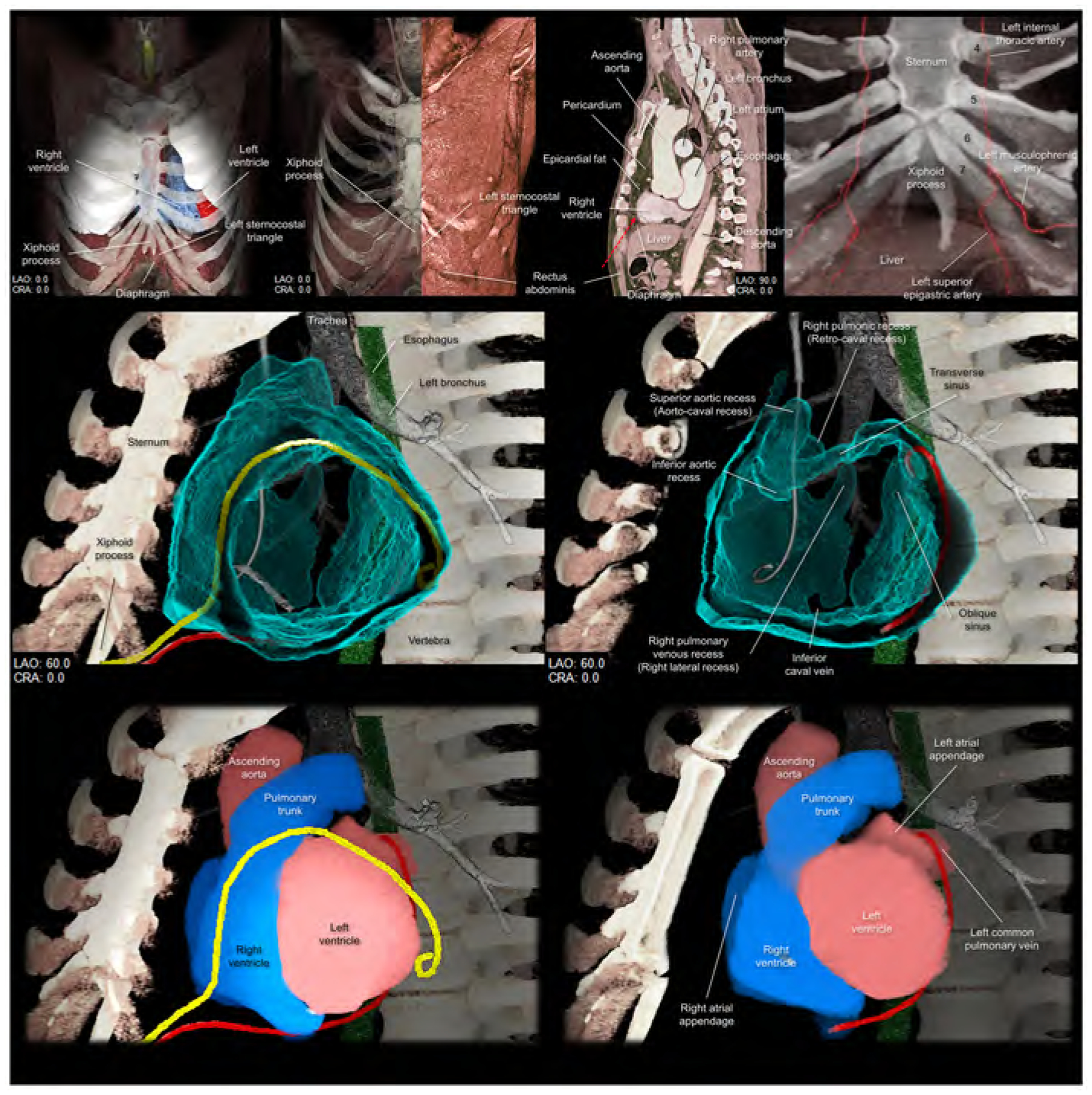
Upper panels focus on the left sternocostal triangle. Left panel shows the frontal view demonstrating the relationship between the xiphoid process, diaphragm, and left sternocostal triangle. Left middle panel shows the rectus abdominis at the left sternocostal triangle. Right middle panel shows the sagittal plane, which is sectioned along the vertical line indicated in the middle panel, demonstrating the relationship between liver, rectus abdominis, and pericardium, and epicardial fat. Red dotted arrow indicates the direction of the epicardial access via the left sternocostal triangle, also called Larrey’s approach. Right panel demonstrates the anatomy of the left superior epigastric artery. Numbers in this panel indicate the costa. Middle panels are virtual dissection images to show the anterior and inferior course of the drainage tube (yellow and red, respectively) via the left sternocostal triangle. Red drainage tube inserted close to the left atrial appendage is reconstructed from the real tube, whereas the yellow drainage tube inserted close to the inferolateral region of the left ventricle is the virtual one. Lower panels are the images viewed from the same directions showing the spatial relationships between the drainage tubes and cardiac chambers. Refer to Supplementary movie 8. CRA, cranial; LAO, left anterior oblique.
Figure 7. Fluoroscopic images and virtual catheters.
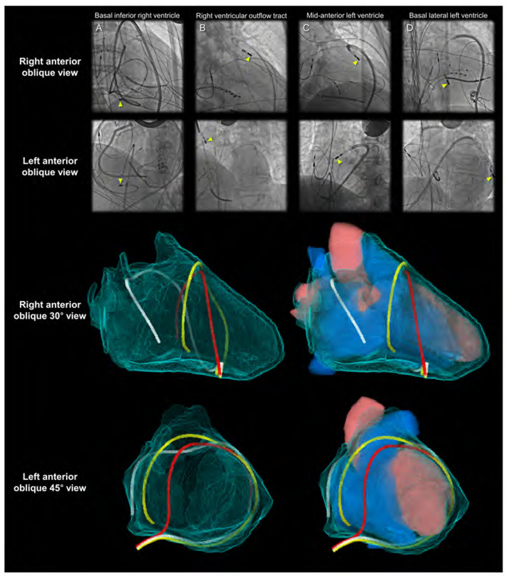
Entire epicardial surface of both ventricles and substantial part of epicardial surface of both atria that are not related to the superior hilum and posterior hilum can be readily approached during epicardial ablation (yellow arrowheads). Note epicardial ablation catheters in the patient A take the inferior course, and those in the other patients B-D take the anterior courses relative to the heart. Patient A shows right coronary angiography performed to confirm spatial relationship between the ablation site and the right coronary artery. In the left anterior oblique view of the patients A and D, the catheters pass through between the left lateral and right lateral regions by surrounding the base-mid of the ventricles. These catheters are located anteriorly to the arterial trunks. The top of the loop is located anteriorly to the pulmonary root. Thus, it is higher than the base of the aortic root. These catheters do not pass through the transverse sinus located posteriorly to the aortic root and inferiorly to the pulmonary trunk. The reconstructed images (lower panels) show the location of the virtual catheters placed in the pericardial space using anterior (red) and posterior (white and yellow) approaches. Guiding the catheter across the transverse sinus (white) of the living heart is virtually feasible. However, it is far easier, safer, and common to guide the catheter anterior to the arterial trunks (red and yellow) beneath the anterior pericardial reflections. Note that the virtual catheter in the transverse sinus does not show a natural smooth loop. Refer to Figure 6.
Limitations
To the best of our knowledge, high-quality three-dimensional images showing the living anatomy of the pericardial space has never been attempted thus far. Although current images enhance further understanding of the pericardial space/recesses/sinuses and hilum of the heart, the readers should appreciate potential wide variation in the structural anatomy related to the pericardial space (18, 21, 51). Further studies will be necessary to quantify and clarify the variation and its clinical implications.
Conclusions
The very act of dissection to reveal the internal features produces some degree of anatomical distortion. This is avoided when using virtual dissection, a volume rendering-based reconstruction technique using living heart dataset, with the added advantage that the hearts are seen in the form retaining in vivo blood-filled shape and attitudinally appropriate relationship to surrounding structures (62–64). Thus, in addition to our recent publication showing anatomical dissections of human hearts with intact pericardium (51), we have sought to explain and demonstrate the three-dimensional living anatomy of the pericardial space in relation to its surrounding structures. We have also provided detailed information regarding the left sternocostal triangle for a better appreciation of subxiphoid access. The data visualized has been provided to the reader as a three-dimensional printable file (Figure 8, Supplementary movie 9, Supplementary 3MF file, Supplementary three-dimensional PDF file). Our review is based on the efforts of several pioneers in the field. We hope the corresponding current three-dimensional information reconstructed from the living heart will further enhance clinical understanding, and will contribute to the future safety and success of the procedure performed within the pericardial space.
Figure 8. Three-dimensional prints of the pericardial ‘space’.
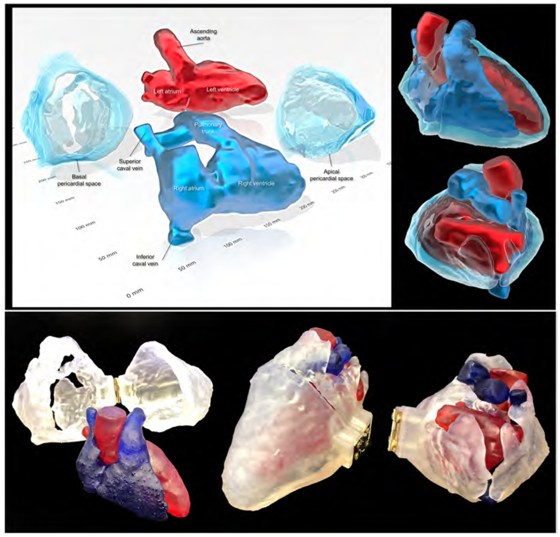
Images reconstructed from the STL file to create three-dimensional printing models (upper panels) using a commercially available software (3D Builder, Microsoft Co. Redmond, WA, USA). Lower panels show real three-dimensional printed models (using the 3MF file that is uploaded with this paper). Refer to Supplementary movie 9, Supplementary 3MF file, and Supplementary three-dimensional PDF file.
Supplementary Material
Supplementary Figure 1. The right coronary angiography after coronary artery bypass grafting
The images are viewed from the cranial 30° direction during systole (left) and diastole (right). Note the fixed relationship betweem the sternal wires and the part of conus branch and right ventricular branch (yellow dotted circles) behind the sternum. In contrast to the main right coronary artery showing vital pulsatile motion, those encircled parts are fixed beneath the sternum due to postoperative pericardial/epicardial adhesion. Refer to Supplementary movies 6, 7.
Supplementary Movie 1. Basal superior views of the solid pericardial space, superior hilum, and posterior hilum. The right and left heart are reconstructed in blue and red, respectively. CRA, cranial; RAO, right anterior oblique.
Supplementary Movie 2. Solid reconstruction of the pericardial space viewed from the apical direction. Red structure is the shock lead. CRA, cranial; LAO, left anterior oblique.
Supplementary Movie 3. Double-layer reconstruction of the pericardial space. The right and left heart are colored in yellow and purple, respectively. Red and white structures are the drainage tube and shock lead, respectively. CRA, cranial; LAO, left anterior oblique; RAO, right anterior oblique.
Supplementary Movie 4. Double-layer reconstruction of the pericardial space with internal heart sectioned from the apical direction. The right and left heart are reconstructed in blue and red, respectively. CRA, cranial; LAO, left anterior oblique.
Supplementary Movie 5. Double-layer reconstruction of the pericardial space with internal heart and external adjacent structures. The right and left heart are colored in yellow and purple, respectively. The trachea and bronchus are shown in white. The esophagus is green, and the phrenic nerves are orange. CRA, cranial; LAO, left anterior oblique; RAO, right anterior oblique.
Supplementary Movie 6. Right coronary angiogrpahy viewed from the cranial 30° direction to show the finding indicating postoperative pericardial/epicardial adhesion involving the part of the conus branch and right ventricular branch directly beneath the sternum.
Supplementary Movie 7. Right coronary angiogrpahy viewed from the left anterior oblique 45° direction to show the finding indicating the postoperative pericardial/epicardial adhesion involving the part of the conus branch and right ventricular branch directly beneath the sternum.
Supplementary Movie 8. Double-layer reconstruction of the pericardial space with real (red) and virtual (yellow) drainage tubes inserted via the left sternocostal triangle. Red tube shows the inferior approach, and yellow tube demonstrates the anterior approach. CRA, cranial; LAO, left anterior oblique.
Supplementary Movie 9. Three-dimensional printed models of the pericardial space placed on a light display rotation base.
Three-dimensional print model in Figure 8 can be generated from this file.
Three-dimensional living anatomy of the pericardial space can be analyzed using this file. Click the red question mark at the left upper corner and select “Trust this document one time only” to start three-dimensional analysis.
Highlights.
Despite increasing application of the epicardial approach, three-dimensional appreciation of the pericardial space remains difficult.
Living anatomy of the pericardial space was reconstructed and was demonstrated with three-dimensional images/prints.
Precise knowledge of the three-dimensional pericardial space will support further sophisticated epicardial interventions.
Acknowledgments
The authors wish to dedicate this paper to the memory of Dr. Sosa (1). We would also like to thank individuals who donated their bodies and tissues for the advancement of education and research through the willed body program at UCLA. We are also grateful to Travis G. Siems and Alex Rodriguez (UCLA Donated Body Program), Edwin Ng (UCLA Surgical Sciences Laboratory), and Grace Chang (Department of Surgery at UCLA) for their support in the dissections. The authors are thankful to Marc-Anthony Lecky (Department of Radiological Sciences at UCLA) for his support for three-dimensional printing. The authors would also like to thank Yuki Inoue and Kingo Shichinohe (AMIN Co., Ltd.) for technical support for image reconstruction. We also appreciate Takayoshi Toba (Division of Cardiovascular Medicine, Department of Internal Medicine, Kobe University Graduate School of Medicine) for his support for collection of supplementary images.
Funding:
This work was made possible by support from NIH grants OT2OD023848 to KS
Footnotes
Publisher's Disclaimer: This is a PDF file of an unedited manuscript that has been accepted for publication. As a service to our customers we are providing this early version of the manuscript. The manuscript will undergo copyediting, typesetting, and review of the resulting proof before it is published in its final form. Please note that during the production process errors may be discovered which could affect the content, and all legal disclaimers that apply to the journal pertain.
Conflict of interest: None
References
- 1.Sosa E, Scanavacca M, d’Avila A, Pilleggi F. A new technique to perform epicardial mapping in the electrophysiology laboratory. J Cardiovasc Electrophysiol 1996;7:531–6. [DOI] [PubMed] [Google Scholar]
- 2.Wood MA. Percutaneous pericardial instrumentation in the electrophysiology laboratory: a case of need. Heart Rhythm 2006;3:11–2. [DOI] [PubMed] [Google Scholar]
- 3.Sacher F, Roberts-Thomson K, Maury P, et al. Epicardial ventricular tachycardia ablation a multicenter safety study. J Am Coll Cardiol 2010;55:2366–72. [DOI] [PubMed] [Google Scholar]
- 4.Swale M, Mikell S, Gard J, Munger TM, Asirvatham SJ, Friedman PA. Epicardial access: patient selection, anatomy, and a stepwise approach. J Innov Card Rhythm Manag 2011;2:239–49. [Google Scholar]
- 5.Bradfield JS, Tung R, Boyle NG, Buch E, Shivkumar K. Our approach to minimize risk of epicardial access: standard techniques with the addition of electroanatomic mapping guidance. J Cardiovasc Electrophysiol 2013;24:723–7. [DOI] [PMC free article] [PubMed] [Google Scholar]
- 6.Tung R, Michowitz Y, Yu R, et al. Epicardial ablation of ventricular tachycardia: an institutional experience of safety and efficacy. Heart Rhythm 2013;10:490–8. [DOI] [PubMed] [Google Scholar]
- 7.Romero J, Shivkumar K, Di Biase L, et al. Mastering the art of epicardial access in cardiac electrophysiology. Heart Rhythm 2019;16:1738–49. [DOI] [PubMed] [Google Scholar]
- 8.Boyle NG, Shivkumar K. Epicardial interventions in electrophysiology. Circulation 2012;126:1752–69. [DOI] [PMC free article] [PubMed] [Google Scholar]
- 9.Shivkumar K Catheter Ablation of Ventricular Arrhythmias. N Engl J Med 2019;380:1555–64. [DOI] [PubMed] [Google Scholar]
- 10.Valderrábano M, Cesario DA, Ji S, et al. Percutaneous epicardial mapping during ablation of difficult accessory pathways as an alternative to cardiac surgery. Heart Rhythm 2004;1:311–6. [DOI] [PubMed] [Google Scholar]
- 11.Buch E, Shivkumar K. Epicardial catheter ablation of atrial fibrillation. Minerva Med 2009;100:151–7. [PubMed] [Google Scholar]
- 12.Horowitz BN, Vaseghi M, Mahajan A, et al. Percutaneous intrapericardial echocardiography during catheter ablation: a feasibility study. Heart Rhythm 2006;3:1275–82. [DOI] [PubMed] [Google Scholar]
- 13.Shivkumar K Percutaneous epicardial ablation of atrial fibrillation. Heart Rhythm 2008;5:152–4. [DOI] [PubMed] [Google Scholar]
- 14.Buch E, Nakahara S, Shivkumar K. Intra-pericardial balloon retraction of the left atrium: a novel method to prevent esophageal injury during catheter ablation. Heart Rhythm 2008;5:1473–5. [DOI] [PMC free article] [PubMed] [Google Scholar]
- 15.Nakahara S, Ramirez RJ, Buch E, et al. Intrapericardial balloon placement for prevention of collateral injury during catheter ablation of the left atrium in a porcine model. Heart Rhythm 2010;7:81–7. [DOI] [PMC free article] [PubMed] [Google Scholar]
- 16.Buch E, Vaseghi M, Cesario DA, Shivkumar K. A novel method for preventing phrenic nerve injury during catheter ablation. Heart Rhythm 2007;4:95–8. [DOI] [PMC free article] [PubMed] [Google Scholar]
- 17.Miller MA, Gangireddy SR, Doshi SK, et al. Multicenter study on acute and long-term safety and efficacy of percutaneous left atrial appendage closure using an epicardial suture snaring device. Heart Rhythm 2014;11:1853–9. [DOI] [PubMed] [Google Scholar]
- 18.McAlpine WA. Heart and Coronary Arteries: An Anatomical Atlas for Clinical Diagnosis, Radiological Investigation, and Surgical Treatment. New York: Springer-Verlag; 1975. [Google Scholar]
- 19.Choe YH, Im JG, Park JH, Han MC, Kim CW. The anatomy of the pericardial space: a study in cadavers and patients. AJR Am J Roentgenol 1987;149:693–7. [DOI] [PubMed] [Google Scholar]
- 20.Spodick DH. Macrophysiology, microphysiology, and anatomy of the pericardium: a synopsis. Am Heart J 1992;124:1046–51. [DOI] [PubMed] [Google Scholar]
- 21.Chaffanjon P, Brichon PY, Faure C, Favre JJ. Pericardial reflection around the venous aspect of the heart. Surg Radiol Anat 1997;19:17–21. [DOI] [PubMed] [Google Scholar]
- 22.D’Avila A, Scanavacca M, Sosa E, Ruskin JN, Reddy VY. Pericardial anatomy for the interventional electrophysiologist. J Cardiovasc Electrophysiol 2003;14:422–30. [DOI] [PubMed] [Google Scholar]
- 23.Syed F, Lachman N, Christensen K, et al. The Pericardial Space: Obtaining Access and an Approach to Fluoroscopic Anatomy. Card Electrophysiol Clin 2010;2:9–23. [DOI] [PubMed] [Google Scholar]
- 24.Lachman N, Syed FF, Habib A, et al. Correlative anatomy for the electrophysiologist, Part I: the pericardial space, oblique sinus, transverse sinus. J Cardiovasc Electrophysiol 2010;21:1421–6. [DOI] [PubMed] [Google Scholar]
- 25.Rodriguez ER, Tan CD. Structure and Anatomy of the Human Pericardium. Prog Cardiovasc Dis 2017;59:327–40. [DOI] [PubMed] [Google Scholar]
- 26.Gelsomino S, Corradi D, Lorusso R, et al. Anatomical basis of minimally invasive epicardial ablation of atrial fibrillation. Eur J Cardiothorac Surg 2013;43:673–82. [DOI] [PubMed] [Google Scholar]
- 27.Black CM, Hedges LK, Javitt MC. The superior pericardial sinus: normal appearance on gradient-echo MR images. AJR Am J Roentgenol 1993;160:749–51. [DOI] [PubMed] [Google Scholar]
- 28.de Schlichting E, Robert Y, Selek L, Palombi O, Chaffanjon P. A three-dimensional (3D) representation of pericardial cavity based on computed tomography (CT). Surg Radiol Anat 2015;37:199–204. [DOI] [PubMed] [Google Scholar]
- 29.Żurada A, Ustymowicz A, Loukas M, Michalak M, Czyżewska D, Gielecki J. Computerized tomography of the transverse pericardial sinus: Normal or pathologic? Clin Anat 2017;30:61–70. [DOI] [PubMed] [Google Scholar]
- 30.Mori S, Shivkumar K. Three-dimensional imaging of the pericardial space. HeartRhythm Case Rep 2020;6:194–7. [DOI] [PMC free article] [PubMed] [Google Scholar]
- 31.Pauza DH, Pauziene N, Tamasauskas KA, Stropus R. Hilum of the heart. Anat Rec 1997;248:322–4. [DOI] [PubMed] [Google Scholar]
- 32.Hildreth V, Webb S, Bradshaw L, Brown NA, Anderson RH, Henderson DJ. Cells migrating from the neural crest contribute to the innervation of the venous pole of the heart. J Anat 2008;212:1–11. [DOI] [PMC free article] [PubMed] [Google Scholar]
- 33.Tomanek RJ. Developmental Progression of the Coronary Vasculature in Human Embryos and Fetuses. Anat Rec (Hoboken) 2016;299:25–41. [DOI] [PMC free article] [PubMed] [Google Scholar]
- 34.Faridah Y, Julsrud PR. Congenital absence of pericardium revisited. Int J Cardiovasc Imaging. 2002;18:67–73. [DOI] [PubMed] [Google Scholar]
- 35.Moorman A, Webb S, Brown NA, Lamers W, Anderson RH. Development of the heart: (1) formation of the cardiac chambers and arterial trunks. Heart 2003;89:806–14. [DOI] [PMC free article] [PubMed] [Google Scholar]
- 36.Lin CJ, Lin CY, Chen CH, Zhou B, Chang CP. Partitioning the heart: mechanisms of cardiac septation and valve development. Development 2012;139:3277–99. [DOI] [PMC free article] [PubMed] [Google Scholar]
- 37.Anderson RH, Brown NA, Moorman AF. Development and structures of the venous pole of the heart. Dev Dyn 2006;235:2–9. [DOI] [PubMed] [Google Scholar]
- 38.Elbatran AI, Anderson RH, Mori S, Saba MM. The rationale for isolation of the left atrial pulmonary venous component to control atrial fibrillation: A review article. Heart Rhythm 2019;16:1392–8. [DOI] [PubMed] [Google Scholar]
- 39.Saremi F, Mekhail S, Sefidbakht S, Thonar B, Malik S, Sarlaty T. Quantification of epicardial adipose tissue: correlation of surface area and volume measurements. Acad Radiol 2011;18:977–83. [DOI] [PubMed] [Google Scholar]
- 40.Nakahara S, Hori Y, Kobayashi S, et al. Epicardial adipose tissue-based defragmentation approach to persistent atrial fibrillation: its impact on complex fractionated electrograms and ablation outcome. Heart Rhythm 2014;11:1343–51. [DOI] [PubMed] [Google Scholar]
- 41.Nakagawa H, Scherlag BJ, Patterson E, Ikeda A, Lockwood D, Jackman WM. Pathophysiologic basis of autonomic ganglionated plexus ablation in patients with atrial fibrillation. Heart Rhythm 2009;6:S26–34. [DOI] [PubMed] [Google Scholar]
- 42.Lachman N, Syed FF, Habib A, et al. Correlative anatomy for the electrophysiologist, part II: cardiac ganglia, phrenic nerve, coronary venous system. J Cardiovasc Electrophysiol 2011;22:104–10. [DOI] [PubMed] [Google Scholar]
- 43.Tung R, Nakahara S, Ramirez R, Lai C, Fishbein MC, Shivkumar K. Distinguishing epicardial fat from scar: analysis of electrograms using high-density electroanatomic mapping in a novel porcine infarct model. Heart Rhythm 2010;7:389–95. [DOI] [PMC free article] [PubMed] [Google Scholar]
- 44.Tung R, Shivkumar K. The value of image integration for epicardial catheter ablation of ventricular tachycardia. J Am Coll Cardiol IMG 2013;6:53–5. [DOI] [PubMed] [Google Scholar]
- 45.Nishimori M, Kiuchi K, Mori S, et al. Atypical inferoseptal accessory pathway connection associated with an aneurysm of the coronary sinus: Insight from a three-dimensional combined image of electroanatomic mapping and computed tomography. HeartRhythm Case Rep 2018;4:389–92. [DOI] [PMC free article] [PubMed] [Google Scholar]
- 46.Takeshige R, Mori S, Nishii T, et al. Cardiac apical swinging detected by computed tomography. Echocardiography 2017;34:1950–19. [DOI] [PubMed] [Google Scholar]
- 47.Kawashima T The autonomic nervous system of the human heart with special reference to its origin, course, and peripheral distribution. Anat Embryol (Berl) 2005;209:425–38. [DOI] [PubMed] [Google Scholar]
- 48.Kawashima T Anatomy of the cardiac nervous system with clinical and comparative morphological implications. Anat Sci Int 2011;86:30–49. [DOI] [PubMed] [Google Scholar]
- 49.Mizeres NJ. The Cardiac Plexus in Man. Am J Anat 1963;112:141–51. [Google Scholar]
- 50.Hanna P, Dacey MJ, Brennan J, et al. Innervation and Neuronal Control of the Mammalian Sinoatrial Node: A Comprehensive Atlas. Circ Res 2021; Epub ahead of print. doi: 10.1161/CIRCRESAHA.120.318458. [DOI] [PMC free article] [PubMed] [Google Scholar]
- 51.Mori S, Hanna P, Dacey MJ, et al. Comprehensive Anatomy of the Pericardial Space and the Cardiac Hilum: Anatomical Dissections With Intact Pericardium. J Am Coll Cardiol IMG 2021. [Epub ahead of print]. doi: 10.1016/j.jcmg.2021.04.016. [DOI] [PMC free article] [PubMed] [Google Scholar]
- 52.Jiang R, Buch E, Gima J, et al. Feasibility of percutaneous epicardial mapping and ablation for refractory atrial fibrillation: Insights into substrate and lesion transmurality. Heart Rhythm 2019;16:1151–9. [DOI] [PubMed] [Google Scholar]
- 53.Killu AM, Friedman PA, Mulpuru SK, Munger TM, Packer DL, Asirvatham SJ. Atypical complications encountered with epicardial electrophysiological procedures. Heart Rhythm 2013;10:1613–21. [DOI] [PubMed] [Google Scholar]
- 54.Sato T, Miyamoto K, Nishii T, Kusano K. Pace-and-Ablate Technique for Atrial Tachycardia Originating From the Left Atrial Appendage. Circ J 2020;84:1046. [DOI] [PubMed] [Google Scholar]
- 55.Mathuria N, Buch E, Shivkumar K. Pleuropericardial fistula formation after prior epicardial catheter ablation for ventricular tachycardia. Circ Arrhythm Electrophysiol 2012;5:e18–9. [DOI] [PubMed] [Google Scholar]
- 56.Larrey DJ. New surgical procedure to open the pericardium in the case of fluid in its cavity. Clin Chir 1829;62:95–103. [Google Scholar]
- 57.Tóth I, Rami-Porta R, Rendeki S, Molnár TF. First steps in the management of pericardial effusion: who was first to relieve the pericardial sac--Larrey or Romero? World J Surg 2013;37:2242–5. [DOI] [PubMed] [Google Scholar]
- 58.Tung R, Shivkumar K. Epicardial Ablation of Ventricular Tachycardia. Methodist Debakey Cardiovasc J 2015;11:129–34. [DOI] [PMC free article] [PubMed] [Google Scholar]
- 59.Baudoin YP, Hoch M, Protin XM, Otton BJ, Ginon B, Voiglio EJ. The superior epigastric artery does not pass through Larrey’s space (trigonum sternocostale). Surg Radiol Anat 2003;25:259–62. [DOI] [PubMed] [Google Scholar]
- 60.Fukuzawa K, Nagamatsu Y, Mori S, et al. Percutaneous Pericardiocentesis With the Anterior Approach: Demonstration of the Precise Course With Computed Tomography. J Am Coll Cardiol EP 2019;5:730–41. [DOI] [PubMed] [Google Scholar]
- 61.Nagamatsu Y, Mori S, Fukuzawa K, et al. Anatomical characteristics of the superior epigastric artery for epicardial ablation using the anterior approach. J Cardiovasc Electrophysiol 2019;30:1339–40. [DOI] [PubMed] [Google Scholar]
- 62.Mori S, Spicer DE, Anderson RH. Revisiting the Anatomy of the Living Heart. Circ J 2016;80:24–33. [DOI] [PubMed] [Google Scholar]
- 63.Mori S, Tretter JT, Spicer DE, Bolender DL, Anderson RH. What is the real cardiac anatomy? Clin Anat 2019;32:288–309. [DOI] [PMC free article] [PubMed] [Google Scholar]
- 64.Tretter JT, Gupta SK, Izawa Y, Nishii T, Mori S. Virtual Dissection: Emerging as the Gold Standard of Analyzing Living Heart Anatomy. J Cardiovasc Dev Dis. 2020;7:30. [DOI] [PMC free article] [PubMed] [Google Scholar]
- 65.Mori S, Anderson RH, Nishii T, Matsumoto K, Loomba RS. Isomerism in the setting of the so-called “heterotaxy”: The usefulness of computed tomographic analysis. Ann Pediatr Cardiol 2017;10:175–86. [DOI] [PMC free article] [PubMed] [Google Scholar]
Associated Data
This section collects any data citations, data availability statements, or supplementary materials included in this article.
Supplementary Materials
Supplementary Figure 1. The right coronary angiography after coronary artery bypass grafting
The images are viewed from the cranial 30° direction during systole (left) and diastole (right). Note the fixed relationship betweem the sternal wires and the part of conus branch and right ventricular branch (yellow dotted circles) behind the sternum. In contrast to the main right coronary artery showing vital pulsatile motion, those encircled parts are fixed beneath the sternum due to postoperative pericardial/epicardial adhesion. Refer to Supplementary movies 6, 7.
Supplementary Movie 1. Basal superior views of the solid pericardial space, superior hilum, and posterior hilum. The right and left heart are reconstructed in blue and red, respectively. CRA, cranial; RAO, right anterior oblique.
Supplementary Movie 2. Solid reconstruction of the pericardial space viewed from the apical direction. Red structure is the shock lead. CRA, cranial; LAO, left anterior oblique.
Supplementary Movie 3. Double-layer reconstruction of the pericardial space. The right and left heart are colored in yellow and purple, respectively. Red and white structures are the drainage tube and shock lead, respectively. CRA, cranial; LAO, left anterior oblique; RAO, right anterior oblique.
Supplementary Movie 4. Double-layer reconstruction of the pericardial space with internal heart sectioned from the apical direction. The right and left heart are reconstructed in blue and red, respectively. CRA, cranial; LAO, left anterior oblique.
Supplementary Movie 5. Double-layer reconstruction of the pericardial space with internal heart and external adjacent structures. The right and left heart are colored in yellow and purple, respectively. The trachea and bronchus are shown in white. The esophagus is green, and the phrenic nerves are orange. CRA, cranial; LAO, left anterior oblique; RAO, right anterior oblique.
Supplementary Movie 6. Right coronary angiogrpahy viewed from the cranial 30° direction to show the finding indicating postoperative pericardial/epicardial adhesion involving the part of the conus branch and right ventricular branch directly beneath the sternum.
Supplementary Movie 7. Right coronary angiogrpahy viewed from the left anterior oblique 45° direction to show the finding indicating the postoperative pericardial/epicardial adhesion involving the part of the conus branch and right ventricular branch directly beneath the sternum.
Supplementary Movie 8. Double-layer reconstruction of the pericardial space with real (red) and virtual (yellow) drainage tubes inserted via the left sternocostal triangle. Red tube shows the inferior approach, and yellow tube demonstrates the anterior approach. CRA, cranial; LAO, left anterior oblique.
Supplementary Movie 9. Three-dimensional printed models of the pericardial space placed on a light display rotation base.
Three-dimensional print model in Figure 8 can be generated from this file.
Three-dimensional living anatomy of the pericardial space can be analyzed using this file. Click the red question mark at the left upper corner and select “Trust this document one time only” to start three-dimensional analysis.


