Abstract
Cerenkov luminescence tomography (CLT) is a novel and highly sensitive imaging technique, which could obtain the three-dimensional distribution of radioactive probes to achieve accurate tumor detection. However, the simplified radiative transfer equation and ill-conditioned inverse problem cause a reconstruction error. In this study, a novel attention mechanism based locally connected (AMLC) network was proposed to reduce barycenter error and improve morphological restorability. The proposed AMLC network consisted of two main parts: a fully connected sub-network for providing a coarse reconstruction result, and a locally connected sub-network based on an attention matrix for refinement. Both numerical simulations and in vivo experiments were conducted to show the superiority of the AMLC network in accuracy and stability over existing methods (MFCNN, KNN-LC network). This method improved CLT reconstruction performance and promoted the application of machine learning in optical imaging research.
1. Introduction
Cerenkov luminescence imaging (CLI) is a novel optical molecular imaging method based on the Cerenkov radiation of nuclides [1]. Combining the advantages of optical imaging and radionuclide imaging [2], CLI has high sensitivity and facilitates clinical transformation [3,4]. Recently, CLI has been widely used in preclinical and clinical research, such as apoptosis visualization [5], tumor resection [6], monitoring drug therapy [7]. However, CLI is a planar imaging method, which could not restore the internal distribution of radioactive probes [8]. Therefore, Cerenkov luminescence tomography (CLT) has been developed [9–11].
CLT matches the surface optical information with the structure information. Utilizing the efficient photon transmission model and image reconstruction algorithm, the three-dimensional (3D) distribution of specific molecular probes in biological tissue could be restored from the surface optical signals. CLT reconstruction consists of two main steps: forward problem solving and inverse problem solving [12–14]. To solve the forward problem, a mathematical model is conducted to describe the photon transmission process and establish the mapping from the 3D distribution of the source to the surface signal. The inverse problem solving is to restore the 3D distribution of sources in organisms based on the distribution of surface signals [15]. Several model-based methods were proposed to solve the ill-posed problems. Diffusion equation and simplified spherical harmonics equation were applied to simplify the radiative transfer equation [16–18]. The weighted combination of spectral information was applied to optimize CLT performance [19,20]. For the inverse problem, the prior information was introduced to reduce the ill-posedness. Greedy strategy [21] and iterative optimization strategy [22] were widely applied. Besides, more researchers focused on the relationship between adjacent nodes to establish regular terms [23,24]. Although ideal reconstruction results could be obtained by these strategies, time cost and approximation error still limit the application of CLT.
Recently, machine learning strategies are widely used in medicine [25]. The development of machine learning shows great potential in optical tomography reconstruction. Through end-to-end learning, the reconstruction methods based on machine learning could fundamentally avoid approximation errors. A Gated Recurrent Unit based network was proposed to improve the accuracy and speed of single-source reconstruction [26]. Meanwhile, a 3D encoder-decoder network achieved dual-source fluorescence molecular tomography (FMT) reconstruction [27]. However, in vivo experiments were absent. Recently, a fusion dual-sampling UHR-DeepFMT method achieved in vivo glass tubes reconstruction, which greatly improved the spatial resolution of reconstruction [28]. In addition, finite element mesh method provides another thought for optical reconstruction. The in vivo reconstructions of the bioluminescence tomography (BLT) and CLT were implemented respectively with an inverse problem simulation [29] and a multilayer fully connected neural network (MFCNN) [30]. The combination of K-nearest neighbors strategy and ResNet improved the morphological reconstruction of FMT [31]. However, the complicated process of K selection limited its application. Although significant progress has been made in optical tomography reconstruction, the over-sparse problem and the differences between datasets still affect the accuracy of reconstruction.
In this study, an attention mechanism based locally connected (AMLC) network was proposed to improve CLT reconstruction performance. AMLC network was inspired by KNN-LC network, which had great performance in solving over-sparse problem. The fully connected (FC) sub-network provided a coarse result, which was used to establish the attention matrix. Based on it, the locally connected (LC) sub-network was conducted. Numerical simulation experiments and in vivo experiments were carried out to assess AMLC network performance. Meanwhile, MFCNN and KNN-LC network were used for comparisons. The experimental results revealed significant improvement in tumor localization and morphological restoration. The research flow diagram is provided in Supplement 1 (1.5MB, pdf) (Fig. S1).
2. Methods
2.1. Machine learning for CLT reconstruction
CLT reconstruction methods based on machine learning use neural network to establish end-to-end mapping and directly reconstruct the internal source. Thus, the deviation between the simplified photon propagation process and the real photon propagation process could be avoided. Parameters of the nonlinear mapping are directly obtained from statistical learning. The objective function is described as follows:
| (1) |
where f s represents the reconstruction system. θ is the system weight which is updated by minimizing the mean square error. The system input is the surface photon intensity X and the output is the reconstructed source Y.
2.2. Structure of the AMLC network
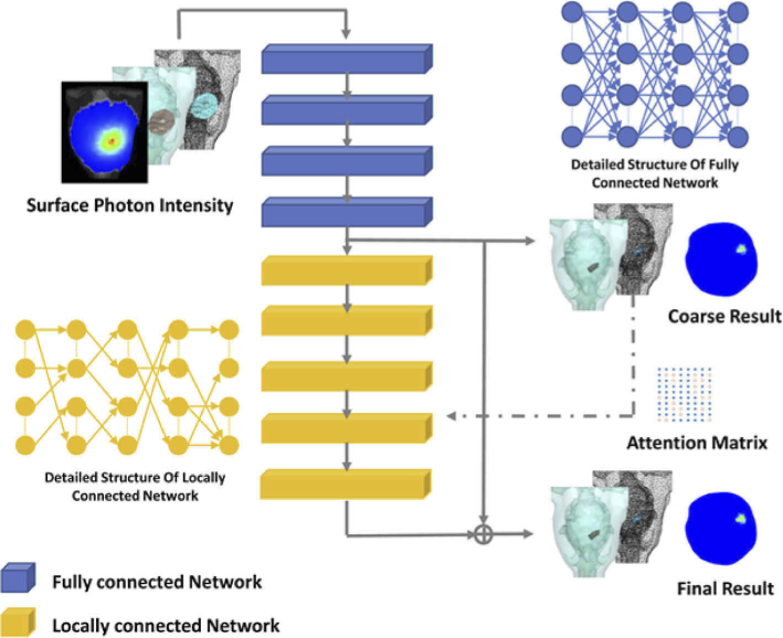
AMLC network consisted of two main parts: the FC sub-network for the acquisition of coarse results and the LC sub-network for residual optimization (Fig. 1). Attention mechanism was introduced to optimize the residual between coarse results and targets. Specifically, surface photon density was first fed to the FC sub-network to obtain a coarse source. Then the residual was generated from the LC sub-network, and it was combined with the coarse result into the final reconstruction result. The whole CLT reconstruction procedure can be defined as:
| (2) |
where f FC is the FC sub-network with weights , while f LC represents the LC sub-network with weights . The output of the FC sub-network is Y FC . The system input is the surface photon intensity X, and the output is the reconstructed source Y. A parameter λ is added to balance the two losses, which is set to 0.2 in our experiment.
Fig. 1.
The overall pipeline of AMLC network. The blue blocks represent the fully connected (FC) sub-network. The yellow blocks represent the locally connected (LC) sub-network. Attention matrix is constructed based on coarse results.
The FC sub-network used four fully connected layers to obtain the coarse results. The activation function was Rectified linear unit (ReLU).
| (3) |
The LC sub-network consisted of five locally connected layers. The number of neurons in each layer was consistent with the dimension of the coarse results. Therefore, the output nodes of each layer and the input nodes of the next layer could form a square matrix. AMLC network used photon intensity as a restriction. Each dimension in the coarse results recorded photon intensity. Based on the attention mechanism, important dimensions were selected as the main nodes for connection.
Specifically, the photon intensity in each dimension was summed from the coarse results and labels. A SoftMax function was applied to calculate the probability. Due to the huge cardinality, plenty of vertices were closed to zero. For the nonzero locations, the value was set to 1 to indicate that they were more important. After that, two sets of one-dimensional vectors were obtained with values of only 0 and 1. The vector from the coarse results was used to constrain the input nodes, while the vector from the labels was applied to constrain the output nodes. Nodes were disconnected only if both input and output values were 0. The attention matrix A is defined as:
| (4) |
| (5) |
where a ij shows the relationship between the input and output nodes. VCRi represents the ith dimension of the vector calculated by the coarse results. VLj indicates the jth dimension of the label vector. When VCRi and VLj are both 0, nodes i and j are disconnected, otherwise they are connected.
In this study, the whole numerical mouse head model was composed of 11494 single discrete points, including 1965 coordinate points for the brain and 2723 coordinate points for the surface tissue. Based on the distribution of surface vertices, the number of neurons in the first layer of the FC sub-network was set to 2723. The mean square error was adopted as the loss function. AMLC network was trained for 400 epochs with a batch size of 128. The optimization function was Adam optimizer with a learning rate of 0.001, β1 of 0.9, and β2 of 0.99.
2.3. Optical parameters and simulation dataset
As a data-driven method, AMLC network needed plenty of samples for model training. Monte Carlo simulation was used as an alternative method to overcome the difficulty of obtaining a large amount of in vivo experimental data. As mentioned above, the finite element method was used to divide the numerical mouse head into a standard mesh. Three main organs were chosen from the segmented CT data: muscle, skull, and brain, to simulate photon propagation in the head. The absorption coefficient µa and the scattering coefficient µs were acquired from previous study in Table 1 [30]. With Monte Carlo simulation method, thousands of samples were collected to train the network. Each sample was obtained from a standard mesh.
Table 1. Optical parameters of main organs.
| Organ | Absorption coefficient µa | Scattering coefficient µs |
|---|---|---|
| Brain | 0.0389 | 17.134 |
| Skull | 0.0807 | 20.690 |
| Muscle | 0.1154 | 4.674 |
In the previous research, small sample size, single sample type and rough assembly affected the reconstruction results to some extent. In this study, we enlarged the sample size, changed the source shape, optimized the big-source generation strategy, and generated a dataset dominated by dual-source samples. 100,000 photons were assigned to each generated source sample. The photon wavelength was set to 650nm to ensure appropriate penetration and photon intensity [19,20]. Furthermore, different types of sources were assigned to increase data diversity. 439 centers of ellipsoid sources, 418 centers of cylinder sources, and 393 centers of cuboid sources were collected in the reconstruction permissible region (Table 2). Simulations of each center were repeated for 4 times to ensure the randomness of photon propagation. In conclusion, 5000 single-source samples were obtained with three different shapes and 1250 different locations.
Table 2. Features of single-source simulation.
| Shape of the source | Size of the source (mm) | Number of the center | Number of the source |
|---|---|---|---|
| Ellipsoid | Radius 0.5 | 439 | 1756 |
| Cylinder | Long axis 1; Short axis 0.6; Height 2 | 418 | 1672 |
| Cube | Length 2; Width 1; Height 1 | 393 | 1572 |
Dual-source samples were assembled by single-source samples to improve the universality of CLT reconstruction. Different positions were selected and combined randomly to generate the composite sources. Specifically, each single-source sample had a corresponding central coordinate. In the reconstruction feasible region, two samples of single-source with different coordinates were randomly selected for combination. At the same time, a weighted sum of source intensities was performed to get the photon intensity of a dual-source sample. The assembly formulas of surface photon intensity and actual source of multi-source samples were as follows:
| (6) |
| (7) |
where Xmul represents the assembled surface photon and Ymul represents the assembled source. SS is the set of the generated single-source samples. Two single-source samples (n = 2) are selected randomly to assemble the dual-source sample.
The structure of big-source sample was similar to that of dual-source. A single-source sample was selected as the center to assemble the nearest single-source samples into a whole [31]. Considering the randomness of central positions and sizes, only a certain quantity of the assembly was achievable. Therefore, another 500 different centers were generated to avoid the assembly errors. The details of sample parameters and sizes were shown in Table 3.
Table 3. Features of big-source simulation.
| Shape of the source | Size of the source (mm) | Number of the center | Number of the source |
|---|---|---|---|
| Ellipsoid | Radius 1 | 180 | 720 |
| Cylinder | Long axis 2; Short axis 1.2; Height 4 | 160 | 640 |
| Cube | Length 4; Width 2; Height 2 | 160 | 640 |
In conclusion, we generated 5000 single-source samples, 7800 dual-source samples (3000 spheroid sources, 2400 cylindroid sources, and 2400 cuboid sources), and 2000 big-source samples. 80% of the dataset was used for training and 20% for testing. The simulation dataset was generated in Molecular Optical Simulation Environment (MOSE 2.3) [32].
2.4. Numerical simulation experiments
Based on the standard mesh, several numerical simulation experiments were carried out to evaluate the performance of AMLC network. MFCNN and KNN-LC network were used for comparisons. Simulation experiments of single-source, dual-source and big-source were designed to verify the location accuracy and morphology restorability. Furthermore, a group of sources at different depth was generated to explore the effect of depth on reconstruction. Also, we designed a dual-source distance experiment. The center distance was set at 2.5, 3.0 and 3.5 mm to evaluate the reconstruction performance in close sources. Besides, the anti-noise simulation experiment evaluated the robustness of AMLC network. Jupyter Notebook and Python 3.6 were used to train and test three networks. All the numerical simulation experiments were conducted on a personal computer with an Intel Core i7 CPU (4.00 GHz) and an NVidia GTX1080 Ti GPU.
2.5. In vivo experiments
Cell line U87MG-Luc-GFP was used to conduct the tumor model. 11C-methionine (11C-MET) was chosen as the probe to generate Cerenkov photons. The centrifuged cells (approximately 4 × 10⁶) were mixed with an equal volume of phosphate buffered saline and injected into the mouse head through a micro-injector [30]. BLI was used to observe tumor growth every three days. The glioma model was applied to CLT in vivo experiments after one week of growth.
The MRI data (M3, Aspect Imaging, Israel) was obtained firstly. Then, in vivo CLI was obtained from a pentamodal imaging system [33]. Meanwhile, small animal PET (GENISYS4, Sofie Biosciences, USA) was applied to verify the radionuclide accumulation. Considering the extremely short half-life of 11C-MET, the mouse was transferred to PET acquisition immediately. CT data was obtained from a micro-CT system to acquire the structural information of mouse head. Based on CT data, CLI data was mapped to the standard mesh as network input. In vivo experiments were carried out under 1% isoflurane - oxygen mixture gas anesthesia. All the animal experiments were performed under the guidelines of the Institutional Animal Care and Use Committee of the Fifth Affiliated Hospital, Sun Yat-sen University.
After in vivo imaging, glioma mouse model was sacrificed. First, green fluorescent protein (GFP) images were collected from the frozen sections of the mouse head. Then the frozen sections were stained with hematoxylin and eosin (H&E). Since cell line was labeled with green fluorescent protein (GFP), GFP images and H&E stained results were considered as the gold standard.
2.6. Evaluation index
The reconstruction results were quantitatively evaluated with the barycenter error (BCE) [31] and Dice index [30]. BCE was used to measure the location error between the reconstructed result and the actual source. The equation was shown as follows:
| (8) |
| (9) |
where S is the set of the standard mesh vertex. ci represents the vertex coordinates and li is the intensity. Pr and Pt represent the weighted photon intensity of reconstructed source and actual source, respectively. A smaller deviation is expected.
Also, Dice was applied to assess shape recovery capability. The value of Dice is between 0 and 1. Large Dice represented high morphological similarity and excellent reconstruction performance. The equation was defined:
| (10) |
where A represents the set of reconstructed sources and B represents the set of actual sources.
3. Results
In this section, numerical simulation and in vivo experiments were carried out to assess AMLC network in terms of location capability, morphology restorability, robustness, and in vivo feasibility. This section contained six main experiments, including single-source reconstruction, dual-source reconstruction, big-source reconstruction, anti-noise performance experiments, and in vivo experiments. Besides, two additional experiments were conducted to further explore the influence of distance and depth.
3.1. Single-source reconstruction
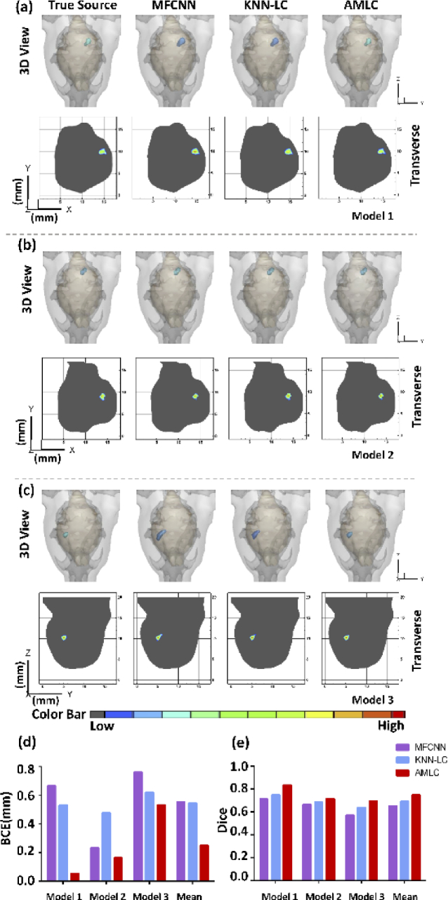
The quantitative analysis of the validation set was shown in Table 4. Three samples, which named model 1, model 2 and model 3 were selected from three different sources to show single-source reconstruction results (Fig. 2). 3D views and 2D cross sections reflected source shapes directly.
Table 4. Quantitative comparison of single-source simulation (mean ± SD).
| Method | MFCNN | KNN-LC | AMLC |
|---|---|---|---|
| BCE (mm) | 0.54 ± 0.43 | 0.46 ± 0.34 | 0.37 ± 0.30 |
| Dice | 0.74 ± 0.16 | 0.78 ± 0.15 | 0.81 ± 0.13 |
Fig. 2.
CLT reconstruction results of single-source. (a-c) show simulation results in different methods, respectively. 3D views and 2D cross sections visually display the reconstruction results. (d) represents BCE of the reconstructed sources, while (e) represents Dice of the reconstructed sources. The mean BCE and Dice of three models are shown in (d) and (e), respectively.
In 3D view, the BCE of AMLC network and KNN-LC network were less than that of MFCNN in model 1 and model 3. Although KNN-LC network achieved accurate positioning, the morphology recovery was unsatisfactory compared with AMLC network in model 3. The model 2 was chosen to demonstrate that AMLC network also achieved an excellent result when MFCNN obtained small BCE. Similar results were also observed in 2D cross sections.
From Table 4, AMLC network showed the minimum mean BCE (0.37 mm) and the maximum mean Dice (0.81) among three methods. More specifically, AMLC network achieved the most accurate CLT reconstruction for model 1, with the minimum BCE (0.05 mm) and the maximum Dice (0.83). These qualitative and quantitative results proved AMLC network was more accurate in single-source reconstruction.
To further verify the superiority of AMLC network, the results of depth experiment were shown in Supplement 1 (1.5MB, pdf) (Fig. S2). All three methods realized the source reconstruction at different depths. With the change of depth, the reconstruction results had different degrees of distortion. Quantitative and qualitative analysis show that AMLC network was more accurate and stable in depth experiment.
3.2. Dual-source reconstruction
Different from the single-source experiment, BCE was considered as the main evaluation index in dual-source reconstruction. The mean BCE of each sub-source in the validation set was calculated and shown in Table 5. The results were consistent with the former experiments. AMLC network obtained the minimum BCE.
Table 5. Quantitative comparison of dual-source simulation (mean ± SD).
| Method | MFCNN | KNN-LC | AMLC |
|---|---|---|---|
| BCE1 (mm) | 0.64 ± 0.33 | 0.59 ± 0.34 | 0.46 ± 0.30 |
| BCE2 (mm) | 0.63 ± 0.32 | 0.54 ± 0.33 | 0.46 ± 0.29 |
| Total BCE (mm) | 1.27 ± 0.68 | 1.13 ± 0.45 | 0.93 ± 0.34 |
Another three samples were selected to show dual-source reconstruction results. Both 3D views and 2D cross sections were provided in Supplement 1 (1.5MB, pdf) (Fig. S3). Quantitative and qualitative analysis show that AMLC network could achieve more accurate dual-source reconstruction.
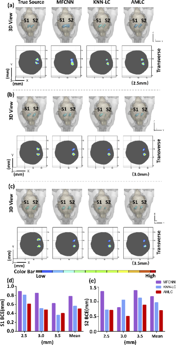
To further evaluate the performance, we narrowed the gap between the two sources. The center distance was set as 2.5 (Fig. 3(a)), 3.0 (Fig. 3(b)) and 3.5 mm (Fig. 3(c)), respectively. As shown in Fig. 3, all three networks had completed the dual-source localization when the barycenter center gap was greater than 3.0 mm. However, when it came to 2.5 mm, it was hard to distinguish dual-source border from the results of MFCNN. When the center distance came to 3.0 mm, S2 source of KNN-LC network was biased. Quantitative analysis was shown in Fig. (d) and (e). The results of AMLC network obtained the minimum mean BCE. These comparisons further verified the superiority of AMLC network in close source reconstruction.
Fig. 3.
CLT reconstruction results of distance experiment. (a-c) show simulation results in different gaps varied from 3.5 to 2.5 mm. Both 3D views and 2D cross sections visually display the reconstruction results. (d-e) represent S1 BCE and S2 BCE, respectively.
3.3. Big-source reconstruction
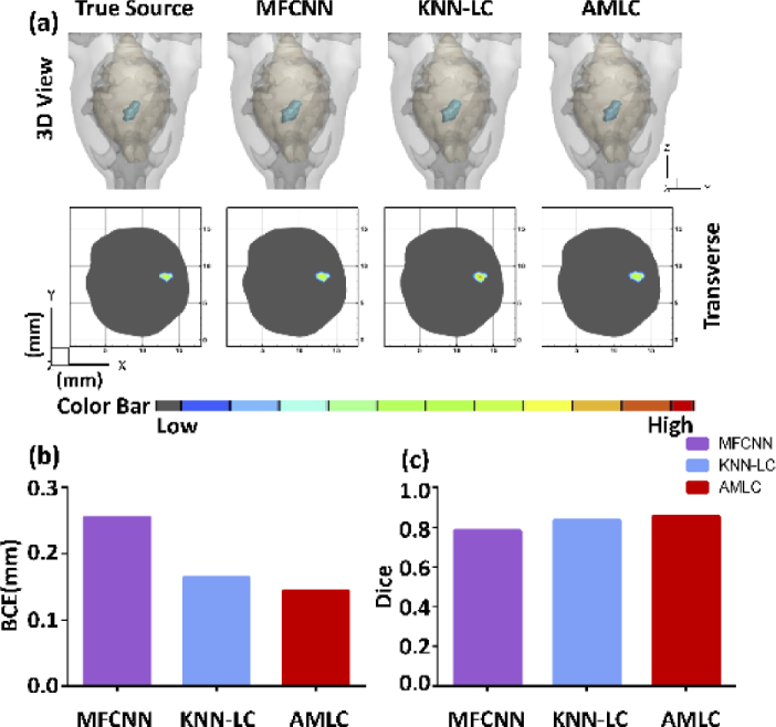
The mean BCE and Dice of validation set were calculated and shown in Table 6 to analyze the reconstruction ability of big-source. As shown in Fig. 4, a big-source sample was selected to show the reconstruction results directly.
Table 6. Quantitative comparison of big -source simulation (mean ± SD).
| Method | MFCNN | KNN-LC | AMLC |
|---|---|---|---|
| BCE (mm) | 0.25 ± 0.18 | 0.16 ± 0.07 | 0.14 ± 0.08 |
| Dice | 0.78 ± 0.06 | 0.84 ± 0.06 | 0.86 ± 0.05 |
Fig. 4.
CLT reconstruction results of the big-source. (a) shows the 3D views and 2D cross sections in different methods. Quantitative analysis is shown in (b-c).
The results in Table 6 were consistent with the previous experiments. The mean BCE of AMLC network was 0.14 which showed a high positioning accuracy. At the same time, AMLC network also obtained the maximum Dice, which meant the morphology of the source obtained the best recovery. These comparisons showed that AMLC network achieved more accurate reconstruction.
3.4. Anti-noise performance experiment
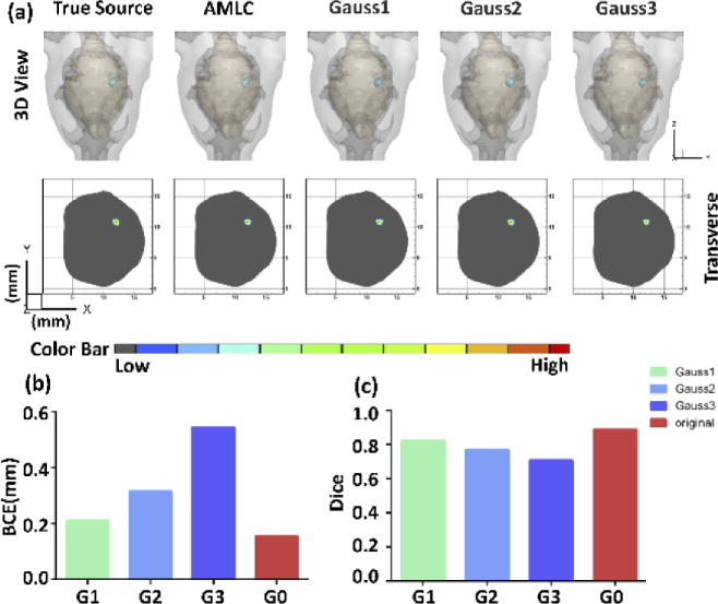
Three different gradients of Gaussian noise were applied in surface photon intensity to assess the stability of AMLC network. Gauss1, Gauss2 and Gauss3 represented 5%, 10% and 15% Gaussian noise, respectively. A single-source sample was chosen to show the results in 3D view and 2D transverse sections, directly. Deviations could be observed in the histograms (Fig. 5). Although BCE increased and Dice decreased after adding noise, location and morphological information can be restored. These results demonstrated that AMLC network was robust.
Fig. 5.
CLT reconstruction results of the anti-noise experiment. (a) shows the 3D views and 2D cross sections in different gradients. G0 represents the reconstruction results without noise. G1, G2 and G3 represent independent simulations with 5%,10% and 15% Gaussian noise. Quantitative analysis is shown in (b-c).
3.5. In vivo CLT reconstruction
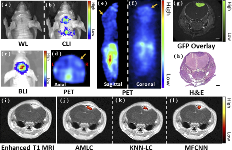
An orthotopic glioma model was used to assess in vivo feasibility of AMLC network. Multi-modality in vivo imaging results were shown in Fig. 6. The reconstructed results were fused with the corresponding MRI data through image registration.
Fig. 6.
In vivo experimental results. (a-c) show the white light (WL) image, CLI and BLI results, respectively. (d-f) show the in vivo PET results. The yellow arrows show the tumor area. (g-h) represent GFP fluorescence image and the H&E stain result. (i-l) show the reconstruction results merged with MRI to evaluate reconstruction performance.
As shown in Fig. 6, both BLI and CLI provided the accurate tumor location. In addition to the head, CLI signals were also observed in the neck of the mouse during signal acquisition. All the results proved that in vivo CLI could obtain tumor localization, which provided the basis for CLT reconstruction.
Enhanced T1 MRI, GFP fluorescence image, and H&E stained image were compared to assess the reconstruction results of the three approaches. The merged CLT-MRI images showed high consistency. The Dice between frozen section and CLT reconstruction was listed in Table 7. Compared with other methods, AMLC network obtained the maximum Dice of 0.69. All the observations demonstrated that AMLC network achieved accurate in vivo CLT reconstruction.
Table 7. Quantitative evaluation (mean ± SD) of in vivo experiment.
| Method | MFCNN | KNN-LC | AMLC |
|---|---|---|---|
| Dice | 0.42 | 0.51 | 0.69 |
4. Discussion and conclusion
CLT is an emerging and highly sensitive imaging method which combines optical information with anatomical information. However, high time cost, complicated solving process, and significant approximation error seriously influence the application of traditional model-based CLT reconstruction methods. Neural networks such as KNN-LC network and MFCNN have achieved optical tomography reconstruction, which encourages us to explore novel applications of machine learning. In this study, an AMLC network was proposed to improve CLT reconstruction performance.
Compared with the previous researches, we optimized the dataset and innovated the network structure to obtain better reconstruction results. The diversity of the dataset was improved by amplifying the number and type of the samples, and the attention mechanism was introduced to make the network flexible. Specifically, we generated 5000 single-source samples, 2000 big-source samples, and assembled 7800 dual-source samples. Compared with MFCNN method, the number of samples in the training set was expanded. And compared with KNN-LC network, the types of sources were enriched. A series of experiments were designed to evaluate its reconstruction performance. Experimental results verify the accuracy and stability of AMLC network in CLT reconstruction.
During the numerical simulations, the reconstruction results were evaluated from quantitative and qualitative perspectives. AMLC network got the highest Dice and the lowest BCE. Compared with MFCNN method, the reconstruction results were obviously improved in morphology restorability and location capability. These results demonstrated that the residual learning module optimized the sparse problem and improved the morphological reconstruction. Meanwhile, the lowest BCE indicated the superiority of AMLC network in location reconstruction. The constraint of AMLC network is the data itself, while KNN-LC network is constrained by location information. Once the value of k is determined, KNN-LC network is fixed. On the contrary, the structure of the LC sub-network based on attention matrix dynamically changes with data. Therefore, AMLC network might generalize better to various types of data.
In in vivo experiments, an orthotropic glioma model was constructed to further verify the superiority of AMLC network. The CLI result was similar to the BLI result, which provided a basis for in vivo 3D reconstruction. PET results were shown in various views to demonstrate that 11C-MET was ingested by glioma. The signals in the necks of the model were probably caused by brown adipose tissue. As the mouse was under gas anesthesia, their muscles shivered from the cold. Brown adipose tissue mainly existed in the neck. Due to cold stimulation and high metabolism, there were more radionuclide probes and stronger CLI signals. Although all three networks had achieved location reconstruction, the result of MFCNN was obviously over-sparse. KNN-LC optimized it to some extent, but lost part of morphological information. AMLC network achieved the highest Dice of 0.69. It was believed that the combination of MRI, PET and AMLC network may improve the accuracy of tumor detection.
Although the well-trained AMLC network performs well in CLT reconstruction, some flaws still exist and restrict its application. AMLC network is a data-driven method and the quantity and quality of the dataset largely determine the reconstruction performance. Different data sets should match different types of tumors. Also, an extra optimization procedure is required to balance the errors between the standard mesh and the actual structure. Combined with model-based CLT reconstruction methods, the limitations might be overcome, which would be explored in our future work.
In conclusion, a novel AMLC network has been proposed to achieve more accurate and stable CLT reconstruction. Attention mechanism was introduced to optimize the residual between coarse results and targets. The well-trained AMLC network has shown excellent performance in both numerical simulations and in vivo experiments. To our best knowledge, it is the first study that combined attention mechanism with CLT reconstruction, which would promote the application of machine learning in optical tomography reconstruction.
Acknowledgment
The authors thank J. Yang, X. Shi and C. Cao for the assistance of the in vivo experiments.
Funding
National Key Research and Development Program of China10.13039/501100012166 (2017YFA0205200); National Natural Science Foundation of China10.13039/501100001809 (62027901, 81227901, 81930053, 92059207); Beijing Municipal Natural Science Foundation10.13039/501100005089 (JQ19027); the Zhuhai High-level Health Personnel Team Project (Zhuhai HLHPTP201703); the innovative research team of high-level local universities in Shanghai.
Disclosures
The authors declare no conflicts of interest.
Data availability
Data underlying the results presented in this paper are not publicly available at this time but may be obtained from the authors upon reasonable request.
Supplemental document
See Supplement 1 (1.5MB, pdf) for supporting content.
References
- 1.Xu Y., Liu H., Cheng Z., “Harnessing the power of radionuclides for optical imaging: Cerenkov luminescence imaging,” J Nucl Med 52(12), 2009–2018 (2011). 10.2967/jnumed.111.092965 [DOI] [PubMed] [Google Scholar]
- 2.Cai M., Zhang Z., Shi X., Yang J., Hu Z., Tian J., “Non-negative iterative convex refinement approach for accurate and robust reconstruction in cerenkov luminescence tomography,” IEEE Trans Med Imaging 39(10), 3207–3217 (2020). 10.1109/TMI.2020.2987640 [DOI] [PubMed] [Google Scholar]
- 3.Ruggiero A., Holland J. P., Lewis J. S., Grimm J., “Cerenkov luminescence imaging of medical isotopes,” J Nucl Med 51(7), 1123–1130 (2010). 10.2967/jnumed.110.076521 [DOI] [PMC free article] [PubMed] [Google Scholar]
- 4.Grootendorst M. R., Cariati M., Kothari A., Tuch D. S., Purushotham A., “Cerenkov luminescence imaging (CLI) for image-guided cancer surgery,” Clin Transl Imaging 4(5), 353–366 (2016). 10.1007/s40336-016-0183-x [DOI] [PMC free article] [PubMed] [Google Scholar]
- 5.Lu M., Zheng S., Zhang X., Guo H., Shi X., Kang X., Qu Y., Hu Z., Tian J., “Cerenkov luminescence imaging on evaluation of early response to chemotherapy of drug-resistant gastric cancer,” Nanomed. Nanotechnol. 14, 205–213 (2016). 10.1016/j.nano.2017.10.001 [DOI] [PubMed] [Google Scholar]
- 6.Zhang Z., Cai M., Bao C., Hu Z., Tian J., “Endoscopic Cerenkov luminescence imaging and image-guided tumor resection on hepatocellular carcinoma-bearing mouse models,” Nanomedicine 17, 62–70 (2012). 10.1016/j.nano.2018.12.017 [DOI] [PubMed] [Google Scholar]
- 7.Xu Y., Chang E., Liu H., Jiang H., Gambhir S. S., o Z. J. J., Cheng N. M., “Proof-of-concept study of monitoring cancer drug therapy with Cerenkov luminescence imaging,” J Nucl Med 53(2), 312–317 (2012). 10.2967/jnumed.111.094623 [DOI] [PMC free article] [PubMed] [Google Scholar]
- 8.Hu Z., Liang J., Yang W., Fan W., Li C., Ma X., Chen X., Ma X., Li X., Qu X., Wang J., Cao F., Tian J., “Experimental Cerenkov luminescence tomography of the mouse model with SPECT imaging validation,” Opt. Express 18(24), 24441–24450 (2010). 10.1364/OE.18.024441 [DOI] [PubMed] [Google Scholar]
- 9.Li C., Mitchell G. S., Cherry S. R., “Cerenkov luminescence tomography for small-animal imaging,” Opt. Lett. 35(7), 1109–1111 (2010). 10.1364/OL.35.001109 [DOI] [PMC free article] [PubMed] [Google Scholar]
- 10.Spinelli A. E., Kuo C., Rice B. W., Calandrino R., Marzola P., Sbarbati A., Boschi F., “Multispectral Cerenkov luminescence tomography for small animal optical imaging,” Opt. Express 19(13), 12605–12618 (2011). 10.1364/OE.19.012605 [DOI] [PubMed] [Google Scholar]
- 11.Ding X., Wang K., Jie B., Luo Y., Hu Z., Tian J., “Probability method for Cerenkov luminescence tomography based on conformance error minimization,” Biomed. Opt. Express 5(7), 2091–2112 (2014). 10.1364/BOE.5.002091 [DOI] [PMC free article] [PubMed] [Google Scholar]
- 12.An Y., Wang K., Tian J., “Recent methodology advances in fluorescence molecular tomography,” Vis. Comput. Ind. Biomed. Art 1(1), 1 (2018). 10.1186/s42492-018-0001-6 [DOI] [PMC free article] [PubMed] [Google Scholar]
- 13.Dutta J., Ahn S., Joshi A. A., Leahy R. M., “Illumination pattern optimization for fluorescence tomography: theory and simulation studies,” Phys. Med. Biol. 55(10), 2961–2982 (2010). 10.1088/0031-9155/55/10/011 [DOI] [PMC free article] [PubMed] [Google Scholar]
- 14.Qin C., Zhong J., Hu Z., Yang X., Tian J., “Recent advances in Cerenkov luminescence and tomography imaging,” IEEE J. Sel. Top. Quant. 18, 1084–1093 (2011). 10.1109/JSTQE.2011.2161757 [DOI] [Google Scholar]
- 15.Klose A. D., “The forward and inverse problem in tissue optics based on the radiative transfer equation: a brief review,” J. Quant. Spectrosc. Radiat. Transf. 111(11), 1852–1853 (2010). 10.1016/j.jqsrt.2010.01.020 [DOI] [PMC free article] [PubMed] [Google Scholar]
- 16.Chen X., Yang D., Qu X., Hu H., Liang J., Gao X., Tian J., “Comparisons of hybrid radiosity-diffusion model and diffusion equation for bioluminescence tomography in cavity cancer detection,” J. Biomed. Opt. 17(6), 066015 (2012). 10.1117/1.JBO.17.6.066015 [DOI] [PubMed] [Google Scholar]
- 17.Tarvainen T., Vauhkonen M., Kolehmainen V., Kaipio J. P., “Hybrid radiative-transfer-diffusion model for optical tomography,” Appl Opt 44(6), 876–886 (2005). 10.1364/AO.44.000876 [DOI] [PubMed] [Google Scholar]
- 18.Chen X., Zhang Q., Yang D., o J. J. J., Liang A. P., “Hybrid radiosity-SP3 equation based bioluminescence tomography reconstruction for turbid medium with low-and non-scattering regions,” J Appl Phys 115(2), 024702 (2014). 10.1063/1.4862166 [DOI] [Google Scholar]
- 19.Liu H., Yang X., Song T., Bao C., Shi L., Hu Z., Wang K., Tian J., “Multispectral hybrid Cerenkov luminescence tomography based on the finite element SPn method,” J. Biomed. Opt 20(8), 086007 (2015). 10.1117/1.JBO.20.8.086007 [DOI] [PubMed] [Google Scholar]
- 20.Guo H., He X., Liu M., Zhang Z., Hu Z., Tian J., “Weight multispectral reconstruction strategy for enhanced reconstruction accuracy and stability with Cerenkov luminescence tomography,” IEEE Trans Med Imaging 36(6), 1337–1346 (2017). 10.1109/TMI.2017.2658661 [DOI] [PubMed] [Google Scholar]
- 21.Zhang S., Ma X., Wang Y., Wu M., Meng H., Chai W., Wang X., Wei S., Tian J., “Robust reconstruction of fluorescence molecular tomography based on sparsity adaptive correntropy matching pursuit method for stem cell distribution,” IEEE Trans Med Imaging 37(10), 2176–2184 (2018). 10.1109/TMI.2018.2825102 [DOI] [PubMed] [Google Scholar]
- 22.He X., Guo H., Yu J., Zhang X., o Y. J. J., Hou I. O. H. S., “Effective and robust approach for fluorescence molecular tomography based on CoSaMP and SP3 model,” J Innov Opt Heal Sci 09(06), 1650024 (2016). 10.1142/S1793545816500243 [DOI] [Google Scholar]
- 23.Gao Y., Wang K., Jiang S., Liu Y., Ai T., Tian J., “Bioluminescence tomography based on Gaussian weighted Laplace prior regularization for in vivo morphological imaging of glioma,” IEEE Trans. Med. Imaging 36(11), 2343–2354 (2017). 10.1109/TMI.2017.2737661 [DOI] [PubMed] [Google Scholar]
- 24.Meng H., Wang K., Gao Y., Jin Y., Ma X., Tian J., “Adaptive Gaussian weighted laplace prior regularization enables accurate morphological reconstruction in fluorescence molecular tomography,” IEEE Trans. Med. Imaging 38(12), 2726–2734 (2019). 10.1109/TMI.2019.2912222 [DOI] [PubMed] [Google Scholar]
- 25.Li C., Dong D., Li L., Gong W., Li X., Bai Y., Wang M., Hu Z., Zha Y., Tian J., “Classification of severe and critical covid-19 using deep learning and radiomics,” IEEE J. Biomed. Health 24, 3585#x2013;3594 (2020). 10.1109/JBHI.2020.3036722. [DOI] [PMC free article] [PubMed] [Google Scholar]
- 26.Huang C., Meng H., Gao Y., Jiang S., Wang K., Tian J., “Fast and robust reconstruction method for fluorescence molecular tomography based on deep neural network,” Proc. SPIE 10881, 55 (2019). 10.1117/12.2508468 [DOI] [Google Scholar]
- 27.Guo L., Liu F., Cai C., Liu J., Zhang G., “3D deep encoder-decoder network for fluorescence molecular tomography,” Opt. Lett. 44(8), 1892–1895 (2019). 10.1364/OL.44.001892 [DOI] [PubMed] [Google Scholar]
- 28.Zhang P., Fan G., Xing T., Song F., o G. J. I. T., Zhang M. I., “UHR-DeepFMT: ultra-high spatial resolution reconstruction of fluorescence molecular tomography based on 3D fusion dual-sampling deep neural network,” IEEE Trans Med Imaging 40(11), 3217–3228 (2021). 10.1109/TMI.2021.3071556 [DOI] [PubMed] [Google Scholar]
- 29.Gao Y., Wang K., An Y., Jiang S., Meng H., Tian J., “Nonmodel-based bioluminescence tomography using a machine-learning reconstruction strategy,” Optica 5(11), 1451–1454 (2018). 10.1364/OPTICA.5.001451 [DOI] [Google Scholar]
- 30.Zhang Z., Cai M., Gao Y., Shi X., Zhang X., Hu Z., Tian J., “A novel Cerenkov luminescence tomography approach using multilayer fully connected neural network,” Phys Med Biol 64(24), 245010 (2019). 10.1088/1361-6560/ab5bb4 [DOI] [PubMed] [Google Scholar]
- 31.Meng H., Gao Y., Yang X., Wang K., Tian J., “K-nearest neighbor based locally connected network for fast morphological reconstruction in fluorescence molecular tomography,” IEEE Trans Med Imaging 39(10), 3019–3028 (2020). 10.1109/TMI.2020.2984557 [DOI] [PubMed] [Google Scholar]
- 32.Tian J., Molecular Imaging: Fundamentals and Applications (Springer Science & Business Media, 2013). [Google Scholar]
- 33.Liu M., Guo H., Liu H., Zhang Z., Chi C., Hui H., Dong D., Hu Z., o J. J. B., Tian E., “In vivo pentamodal tomographic imaging for small animals,” Biomed. Opt. Express 8(3), 1356–1371 (2017). 10.1364/BOE.8.001356 [DOI] [PMC free article] [PubMed] [Google Scholar]
Associated Data
This section collects any data citations, data availability statements, or supplementary materials included in this article.
Data Availability Statement
Data underlying the results presented in this paper are not publicly available at this time but may be obtained from the authors upon reasonable request.


