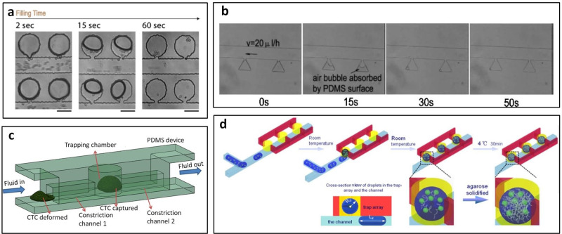
FIG. 13.
Trapping chamber arrangement. (a) Cells were trapped into side chambers from main channels. Reproduced with permission from Cinque et al., Microelectron. Eng. 88, 1733–1736 (2011). Copyright 2011 Elsevier. (b) After being injected into the main channel, the yeast cell suspension was aspirated into micro-cavities by gas absorption of PDMS surface. Reproduced with permission from Luo et al., Biotechnol. Bioeng. 101, 190–195 (2008). Copyright 2008 John Wiley and Sons. (c) CTCs were captured in cylinder trapping chamber while blood cells could pass through the narrow channels. Reproduced with permission from Ren et al., Anal. Chem. 90, 7526–7534 (2018). Copyright 2008 American Chemical Society. (d) The droplets were captured from channel to cylinder traps due surface. Reproduced with permission from Shi et al., Microfluid. Nanofluidics 15, 467–474 (2013). Copyright 2013 Springer Nature.

