Abstract
The study goal was to evaluate the distances from the radial (RN), the musculocutaneous (MN) and axillary nerves (AN) and the medial neurovascular bundle of the upper arm to a minimally invasive applied plate and to define its relation to the RN during different degrees of malrotation during MIPO. The sample involved ten upper extremities. Application of a PHILOS plate was performed through a Delta-split. Intervals between the AN, MN, RN and the medial vascular bundle were defined at various positions. The humeral shaft was artificially fractured at a height of about the mean of the plate. The distal fragment was brought into 15° and 30° internal (IR) as well as external rotation (ER) and here, the plate’s relation to the RN was evaluated. The medial neurovascular bundle intersected the plate at its distal part in two specimens. Regarding the distances from the RN to the plate during different rotation positions the distances became significantly longer during ER, respectively shorter during IR. The medial neurovascular bundle and the RN were identified as the main structures at risk. Care must be taken during distal screw placement and malrotation exceeding 15° must be avoided during MIPO.
Subject terms: Musculoskeletal system, Bone
Introduction
Fractures of the shaft of the humerus represent common injuries, involving 1% to 3% of all fractures, respectively 20% of all fractures of the humerus1–3. Most of these may be treated conservatively. However, the non-operative approach includes the risk of secondary loss of reduction and non-union rates ranging from 2% up to 23% have been reported4. Regarding surgical treatment, plate osteosynthesis and antegrade intramedullary nailing are the most common options. Nevertheless, controversy about the ideal interventional technique still exists. Although open reduction and internal fixation (ORIF) enables anatomical reduction, it includes extensive soft tissue dissection4–6 and despite nerve protection radial nerve (RN) palsies have been described in 5.1–17.6%6. Antegrade intramedullary nailing, although representing a percutaneous method4,7, may lead to rotator cuff lesions with postoperative shoulder dysfunction8, whereas retrograde nailing may be followed by pain around the elbow region. Additionally, minimally invasive plate osteosynthesis (MIPO) has become a popular alternative to these common therapy options. This technique has led to satisfactory outcomes in several clinical trials2,6,7,9,10. It enables minor soft tissue damage in comparison to open methods, earlier postoperative functional treatment2 and biological fracture healing9. Further, fewer infections and cases of RN palsy have been reported4. Nevertheless, Wang and colleagues3 observed an increased postoperative malrotation of the humeral shaft, exceeding 20°, during MIPO in comparison to an ORIF control group.
A helical plate has the potential to avoid an iatrogenic deltoid muscle insertion lesion as well as muscular nerve palsy due to its design. An example from helical MIPO clinical setting is pictured in Fig. 1. The current literature lacks detailed information regarding the proximity of neurovascular structures to the osteosynthesis material after its minimally invasive application in neutral and different rotation positions. Therefore, the purpose of our study was to evaluate the distances from the RN, the musculocutaneous (MN) and axillary nerves (AN) and the medial neurovascular bundle of the upper arm to the applied plate. Furthermore, we aimed to define its relation to the RN during humeral shaft fractures while simulating different degrees of malrotation after MIPO.
Figure 1.
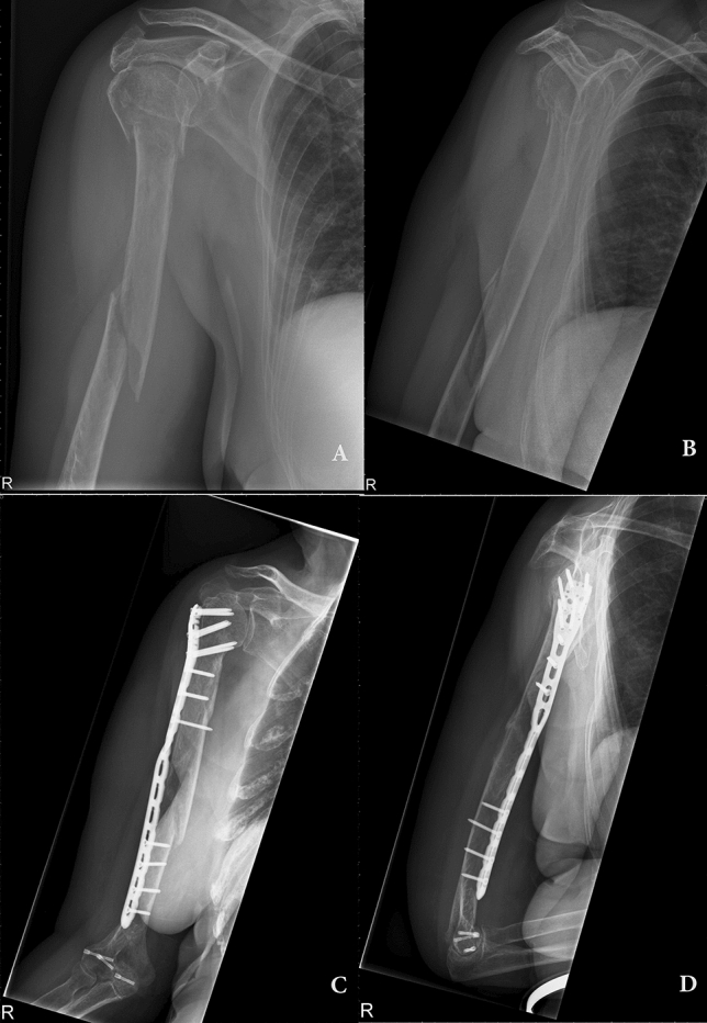
Clinical example of a pre-contoured helical plate in a female 79 years old patient. (A) and (B) preoperative X-ray of a proximal humeral fracture with meta-/diaphyseal extension. (C,D) Six month postoperative X-ray with a helical PHILOS plating system.
Materials and methods
Study sample
The study sample involved ten unpaired upper extremities from ten human adult cadavers embalmed using Thiel’s solution11. All investigated corpses were donated to the Division of Macroscopic and Clinical Anatomy of the Medical University of Graz under the approval of the Anatomical Donation Programme and accordingly to the Austrian curial law. Since these bodies are dedicated to research and scientific teaching, the donors accepted participation in research during their lifetime. All experimental protocols and methods were carried out in accordance with relevant guidelines and regulations. The sample consisted of three limbs from female and seven upper extremities from male donors. Their age ranged from 49 to 92 years with a median of 82. Via inspection of the skin and soft tissues as well as through radiographic control with the C-arm, extremities with former fractures, surgical interventions or malformations in the region of interest were excluded.
Plate application
Primary, the humeral length (HL), which was defined as the distance between the lateral humeral epicondyle (LE) and the tip of the greater tubercle, was evaluated. For implantation, we used a 12-hole PHILOS plate (Synthes GmbH, Oberdorf, Switzerland) which’s middle third had been twisted in a ventral direction in an angle of about 70°–90° over a distance of two plate holes. Access to the proximal part of the humerus was gained through an about six centimetres long skin incision and a Delta-split approach in typical manner. Here, the AN was depicted and countermined with a raspatory. Care was taken not to manipulate the nerve’s original course. Next, the plate was inserted and advanced epiperiosteally to the deltoid tuberosity and the ventral humeral surface. The PHILOS plate was applied to the bone through K-wires about 4 mm posterior to the bicipital grove. The approach to the distal portion of the plate was gained through an about 5 cm skin incision at the distal antero-lateral part of the upper arm which was conducted directly superficial to the palpable plate. Here, after splitting of the fascia, the biceps was retracted in a medial direction following depiction of the MN. The brachial muscle was split at its median part directly superficial to the plate. Here, fixation was conducted through one conventional screw.
Measurement pattern
All measurements were conducted in millimetres and by use of a digital calliper rule. The distance between the proximal margin of the PHILOS plate and the AN as well as the interval between the tip of the greater tubercle and the AN were measured. Additionally, we observed the location of the nerve with regard to the plate’s screw holes.
After plate application, the relationship between the MN and the plate was evaluated. Therefore, the distal skin incision was advanced in a proximal direction. Primary, the ventral crossing point of the plate and the nerve was evaluated and its height with regard to the LE and the distal tip of the plate was measured. Further the distance between the medial margin of the plate and the exit point of the MN from the coracobrachialis was evaluated.
For defining the distances between the plate and the RN, respectively the medial neurovascular bundle three distances were defined: (1) The interval between the medial/lateral border of the plate and the structures at the height of the RN’s exit from the lateral brachial septum, (2) the distance between the plate and the structures at the median point between 1 and 3 and (3) the interval between the medial/lateral edge of the plate and the characteristics at the height of the distal tip of the plate (Figs. 2, 3). For measurement of the RN, the brachialis muscle was split at its median part and the two halves were retracted. For a schematic depiction see Fig. 4.
Figure 2.
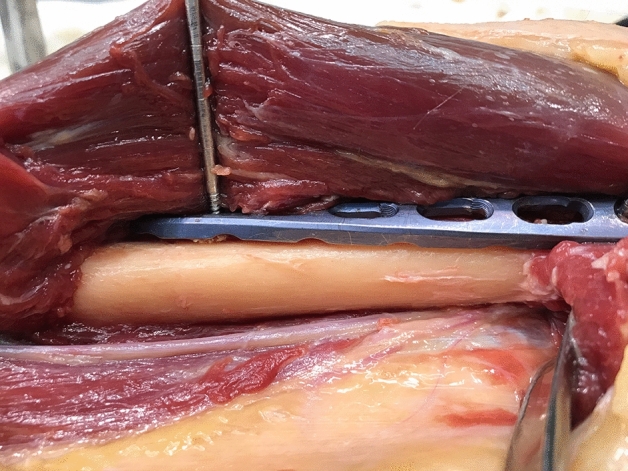
Applicated plate with adjacent RN.
Figure 3.
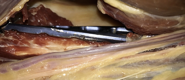
Medial vascular bundle of the upper arm in relation to the minimally invasive inserted plate.
Figure 4.
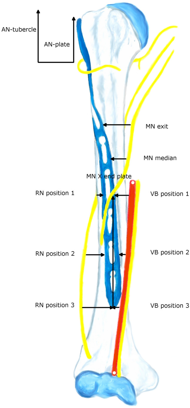
Measurement pattern. AN-plate AN to proximal margin of the plate, AN-tubercle AN to tip of greater tubercle, VB medial vascular bundle for respective position, MN exit exit of MN from coracobrachialis, MN X end plate intersection point of the MN and the plate measured from the distal margin of the plate, MN median measurement point at the middle of the exit and intersection point.
Rotation tests of the RN
After collection of the measurements, the humeral shaft was artificially fractured at a height of about the mean of the plate by use of a circular saw. The distal fragment was brought into 15° internal (IR) and external rotation (ER) as well as 30° IR and ER. In each rotation position, the plate was re-fixed to the distal humeral surface and the distances to the RN were measured at the (above described) positions 1–3.
Statistical analysis
Statistical analysis was conducted using SPSS statistical software (version 24.0; IBM Corp, Armonk, NY, USA). Regarding descriptive statistics, continuous variables are presented as mean, standard deviation (SD), minimum and maximum, whereas categorical data are described as frequencies and percentages. All continuous data were normally distributed. Further, a repeated measurement ANOVA including degrees of distal fracture fragment rotation and radial nerve position as within subject factors was conducted. For comparison of the three different distances between the RN and the plate at different degrees of rotation, t-tests for paired samples were used. Bonferroni adjustment for multiple testing was performed (alpha = 0.05/12 = 0.004).
Results
AN evaluation
The mean distance from the AN to the proximal margin of the plate proved to be 38.9 mm (SD 3.5; range 33.2–44.9) and the interval between the nerve and the tip of the greater tubercle was 48.2 mm (SD 4.9; range 40.5–55.2), see Table 1. Regarding the relation between the AN and the screw holes, the nerve’s most common location was at the proximal of the so-called calcar screws (5 cases/50%).
Table 1.
Measurements in neutral position (in mm).
| AN-plate | AN-tubercle | VB position 1 | VB position 2 | VB position 3 | RN position 1 | |
|---|---|---|---|---|---|---|
| Mean | 38.9 | 48.2 | 16.6 | 15.2 | 13.6 | 8.2 |
| SD | 3.5 | 4.9 | 9.4 | 12.1 | 13.6 | 3.5 |
| Median | 40.0 | 47.5 | 17.1 | 13.7 | 12.0 | 8.0 |
| Min | 33.2 | 40.5 | 1.0 | − 2.0 | − 5.0 | 4.0 |
| Max | 44.9 | 55.2 | 33.0 | 36.0 | 35.0 | 15.0 |
| RN position 2 | RN position 3 | MN exit | MN X end plate | MN X LE | MN median | |
|---|---|---|---|---|---|---|
| Mean | 6.4 | 8.1 | 14.9 | 52.5 | 82.9 | 13.7 |
| SD | 1.5 | 2.3 | 4.5 | 16.0 | 19.4 | 9.9 |
| Median | 6.5 | 8.0 | 16.0 | 53.8 | 77.5 | 10.4 |
| Min | 4.0 | 5.0 | 4.2 | 28.0 | 59.0 | 0.0 |
| Max | 9.0 | 12.0 | 20.6 | 80.0 | 120.0 | 29.0 |
AN-plate AN to proximal margin of the plate, AN-tubercle AN to tip of greater tubercle, VB medial vascular bundle for respective position, MN exit exit of MN from coracobrachialis, MN X end plate intersection point of the MN and the plate measured from the distal margin of the plate, MN X LE intersection point of the MN and the plate measured from the LE, MN median measurement point at the middle of the exit and intersection points, SD standard deviation, min minimum, max maximum.
MN and neurovascular bundle measurements
The mean humeral length was 30.8 cm (SD 3.5) with a range from 23.4 up to 34.6 cm. The distance between the medial neurovascular bundle to the plate was on average 16.6 mm (SD 9.4; range 1–33) at position 1 and 15.2 mm (SD 12.1; range – 2 to 36) at position 2. Regarding position 2, the bundle lay on the plate in one case (with 2 mm from its medial border to the medial margin of the plate; value: − 2 mm). At position 3, the mean interval was 13.6 mm (SD 13.6) with a range from – 5 to 35 mm. Here, the bundle intersected the plate in two specimens.
The distance between the MN and the plate was on average 14.9 mm (SD 4.5; range 4.2–20.6) at its exit point from the coracobrachialis. Regarding its intersection point with the plate, this was at a height of 52.5 mm (SD 16.0; range 28–80) measured from the distal border of the plate, and 82.9 mm (SD 19.4; range 59–120 mm) with regard to the LE. Further, the plate-MN distance was 13.7 mm (SD 9.9 mm; range 0–29) at the median of the two measurement points. Details see Table 1.
RN measurements and rotation tests
Repeated measurement ANOVA revealed statistically significant differences regarding the distances from the RN to the plate during the neutral position against all of the different rotation positions of the distal fracture fragment (p = < 0.001). Thereof, distances became significantly longer during ER, respectively shorter during IR (see Fig. 5).
Figure 5.
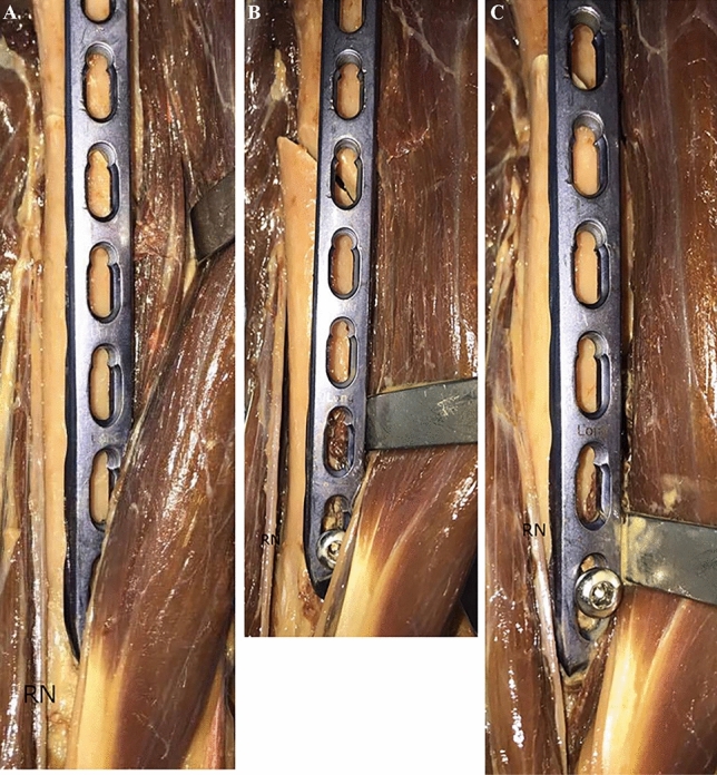
Rotation tests of the RN. (a) Neutral position; (b) external rotation; (c) internal rotation.
With respect to the three different measurement positions, t-test for paired samples showed significantly shorter distances during 15° and 30° IR in comparison to the neutral position for position 1 (p = 0.001). For position 2, IR and ER of 30° revealed significant differences (internal: p = < 0.001; external: p = 0.001). Regarding position 3, all of the rotation positions showed statistically significant differences in comparison to the neutral position (p = < 0.001). For details see Table 2.
Table 2.
Descriptive analysis and outcomes of t-tests for RN testings (in mm).
| Position | Mean | SD | Median | Min | Max | Paired differences | SE mean | df | p-value | |
|---|---|---|---|---|---|---|---|---|---|---|
| Mean | SD | |||||||||
| 1 | ||||||||||
| ER 15° | 9.8 | 2.3 | 9.0 | 7 | 14 | − 1.6 | 3.4 | 1.1 | 9 | .172 |
| ER 30° | 11.6 | 4.5 | 10.5 | 3 | 19 | − 3.4 | 4.8 | 1.5 | 9 | .051 |
| IR 15° | 3.1 | 1.8 | 2.5 | 1 | 6 | 5.1 | 3.5 | 1.1 | 9 | .001 |
| IR 30° | 2.1 | 1.5 | 2.0 | 0 | 5 | 6.1 | 3.8 | 1.2 | 9 | .001 |
| 2 | ||||||||||
| ER 15° | 12.7 | 5.4 | 11.0 | 6 | 22 | − 6.3 | 5.6 | 1.7 | 9 | .006 |
| ER 30° | 15.1 | 5.6 | 13.5 | 9 | 24 | − 8.7 | 5.5 | 1.7 | 9 | .001 |
| IR 15° | 5.0 | 3.4 | 4.0 | 1 | 11 | 1.4 | 3.7 | 1.2 | 9 | .268 |
| IR 30° | 2.0 | 2.2 | 2.5 | − 2 | 5 | 4.4 | 2.6 | 0.8 | 9 | < .001 |
| 3 | ||||||||||
| ER 15° | 11.5 | 2.6 | 12.0 | 8 | 16 | − 3.4 | 2.0 | 0.6 | 9 | < .001 |
| ER 30° | 15.1 | 2.9 | 15.0 | 9 | 20 | − 6.9 | 2.0 | 0.9 | 9 | < .001 |
| IR 15° | 5.3 | 1.6 | 5.5 | 2 | 8 | 2.8 | 1.6 | 0.5 | 9 | < .001 |
| IR 30° | 0.4 | 2.4 | 0.0 | − 3 | 4 | 7.7 | 2.9 | 0.9 | 9 | < .001 |
ER external rotation, IR internal rotation, SD standard deviation, min minimum, max maximum, SE mean standard error of the mean, df degrees of freedom.
Further, the RN was located on the plate in one specimen at position 2 (two millimetres medial to the lateral border of the plate; value: − 2), respectively in two cadavers at position 3 (both three millimetres medial to the lateral edge; value: − 3).
Discussion
MIPO by use of curved implants has recently become a more frequent technique in the treatment of humeral shaft fractures and has resulted in satisfactory clinical outcomes in several studies2,6,7,9,10. The proximity of single nerves to the osteosynthesis material during MIPO has been described in the current literature12,13. However, the intervals between the nerves and the plate at different positions have not been delineated in detail so far.
Gardner and colleagues13 have declared the MN to be the main structure at risk during MIPO. Therefore, they defined a safe zone for its crossing point of the anterior humeral shaft at an interval between 12.2 and 14.8 cm measured from the greater tubercle. We in contrast, found its intersection point with the plate at a height of 52.5 mm starting from the distal border of the plate, respectively 82.9 mm with regard to the LE.
In Křivohlávek et al.’s14 dissection study, a PHILOS plate was applied in 24 specimens through the minimally invasive anterolateral approach. Here, the AN did not suffer injuries in any of the cases. As we performed the plate insertion through a typical Delta-split approach including depiction of the nerve, evaluation of possible iatrogenic lesions was not possible. The mean distance from the AN to the tip of the greater tubercle was at a mean of 48.2 mm with a range from 40.5 up to 55.2 mm in our survey. In comparison, Křivohlávek et al.’s14 intervals were shorter, ranging from 37 to 44 mm. Further, our evaluated mean distance from the AN to the proximal margin of the plate proved to be 38.9 mm which was also slightly greater than in Ninck et al.’s15 dissections (mean of 36.1 mm). With regard to the AN in relation to the proximal screw holes, we evaluated the nerve’s most common location (50%) on the calcar screws. This was also the most frequent position in Křivohlávek et al.’s14 study, however, Ninck and colleagues15 found the AN in most of the cases more distal at region F.
Regarding the medial vascular bundle of the upper arm, we observed the location of this structure on the plate in one specimen at position 2, respectively in two cases at position 3—a fact that needs to be considered during distal screw placement.
With respect to tolerated malrotation during conservative treatment of humeral shaft fractures, this was suggested not to exceed 15°16,17. Further, a postoperative malrotation exceeding 20° was described to be associated with secondary shoulder arthritis18,19. Wang et al.3 observed a significant increase of postoperative malrotation after MIPO in comparison to their ORIF control group. Additionally, the concomitant rotation of the RN during IR and ER of the distal fracture fragments needs to be considered. Our conducted repeated measurement ANOVA showed a statistically significant increase of the intervals between the RN and the lateral border of the plate at the three defined positions during ER, whereas they became significantly shorter during IR. During IR of 30°, we observed the location of the RN directly on the plate in one case at position 2 and in two specimens at position 3.
In conclusion we have examined the relation of a minimally invasive inserted plate to adjacent neurovascular characteristics of the upper arm. We have identified the medial neurovascular bundle and the RN (during IR) as the main structures at risk. Therefore, care must be taken during distal screw placement and malrotation exceeding 15° needs to be avoided. To prohibit the latter, we recommend to place the upper extremity under continuous longitudinal tension and to perform regular X-ray controls during surgery.
Acknowledgements
We give our honest gratitude to all body donors, who gave their informed consent during their lifetime to participate in the studies.
Author contributions
G.M.H.: protocol development; data collection; manuscript writing. G.L.: protocol development; data collection; manuscript writing. A.M.S.: data collection; manuscript writing. P.G.: manuscript writing and editing. M.H.: data analysis; manuscript writing and editing. A.H.W.: protocol development; manuscript writing and editing.
Competing interests
Each author certifies that he or she has no commercial associations (e.g. consultancies, stock ownership, equity interest, patent/licensing arrangements, etc.) that might pose a conflict of interest in connection with the submitted article. All ICMJE Conflict of Interest Forms for authors are on file and can be viewed on request.
Footnotes
Publisher's note
Springer Nature remains neutral with regard to jurisdictional claims in published maps and institutional affiliations.
These authors contributed equally: Gloria Maria Hohenberger and Georg Lipnik.
References
- 1.Ekholm R, Adami J, Tidermark J, Hansson K, Törnkvist H, Ponzer S. Fractures of the shaft of the humerus. An epidemiological study of 401 fractures. J. Bone Joint Surg Br. 2006;88:1469–1473. doi: 10.1302/0301-620X.88B11.17634. [DOI] [PubMed] [Google Scholar]
- 2.Huri G, Biçer ÖS, Öztürk H, Deveci MA, Tan I. Functional outcomes of minimal invasive percutaneous plate osteosynthesis (MIPPO) in humerus shaft fractures: A clinical study. Acta Orthop. Traumatol. Turc. 2014;48:406–412. doi: 10.3944/AOTT.2014.13.0009. [DOI] [PubMed] [Google Scholar]
- 3.Wang C, Li J, Li Y, Dai G, Wang M. Is minimally invasive plating osteosynthesis for humeral shaft fracture advantageous compared with the conventional open technique? J. Shoulder Elbow Surg. 2015;24:1741–1748. doi: 10.1016/j.jse.2015.07.032. [DOI] [PubMed] [Google Scholar]
- 4.Brunner A, Thormann S, Babst R. Minimally invasive percutaneous plating of proximal humeral shaft fractures with the Proximal Humerus Internal Locking System (PHILOS) J. Shoulder Elbow Surg. 2012;21:1056–1063. doi: 10.1016/j.jse.2011.05.016. [DOI] [PubMed] [Google Scholar]
- 5.Bell MJ, Beauchamp CG, Kellam JK, McMurtry RY. The results of plating humeral shaft fractures in patients with multiple injuries. The Sunnybrook experience. J. Bone Joint Surg. Br. 1985;67:293–296. doi: 10.1302/0301-620X.67B2.3980544. [DOI] [PubMed] [Google Scholar]
- 6.Malhan S, Thomas S, Srivastav S, Agarwal S, Mittal V, Nadkarni B, Gulati D. Minimally invasive plate osteosynthesis using a locking compression plate for diaphyseal humeral fractures. J. Orthop. Surg. (Hong Kong). 2012;20:292–296. doi: 10.1177/230949901202000305. [DOI] [PubMed] [Google Scholar]
- 7.Rancan M, Dietrich M, Lamdark T, Can U, Platz A. Minimal invasive long PHILOS®-plate osteosynthesis in metadiaphyseal fractures of the proximal humerus. Injury. 2010;41:1277–1283. doi: 10.1016/j.injury.2010.07.235. [DOI] [PubMed] [Google Scholar]
- 8.Robinson CM, Bell KM, Court-Brown CM, McQueen MM. Locked nailing of humeral shaft fractures. Experience in Edinburgh over a two-year period. J. Bone Joint Surg. Br. 1992;74:558–562. doi: 10.1302/0301-620X.74B4.1624516. [DOI] [PubMed] [Google Scholar]
- 9.Oh HK, Cho DY, Choo SK, Park JW, Park KC, Lee JI. Lessons learned from treating patients with unstable multifragmentary fractures of the proximal humerus by minimal invasive plate osteosynthesis. Arch. Orthop Trauma Surg. 2015;135:235–242. doi: 10.1007/s00402-014-2138-x. [DOI] [PubMed] [Google Scholar]
- 10.Zogaib RK, Morgan S, Belangero PS, Fernandes HJ, Belangero WD, Livani B. Minimal invasive ostheosintesis for treatment of diaphiseal transverse humeral shaft fractures. Acta Ortop Bras. 2014;22:94–98. doi: 10.1590/1413-78522014220200698. [DOI] [PMC free article] [PubMed] [Google Scholar]
- 11.Thiel W. The preservation of the whole corpse with natural color. Ann Anat. 1992;174:185–195. doi: 10.1016/S0940-9602(11)80346-8. [DOI] [PubMed] [Google Scholar]
- 12.Apivatthakakul T, Arpornchayanon O, Bavornratanavech S. Minimally invasive plate osteosynthesis (MIPO) of the humeral shaft fracture. Is it possible? A cadaveric study and preliminary report. Injury. 2005;36:530–538. doi: 10.1016/j.injury.2004.05.036. [DOI] [PubMed] [Google Scholar]
- 13.Gardner MJ, Griffith MH, Lorich DG. Helical plating of the proximal humerus. Injury. 2005;36:1197–1200. doi: 10.1016/j.injury.2005.06.038. [DOI] [PubMed] [Google Scholar]
- 14.Křivohlávek M, Taller S, Lukáš R, Dráč P. Anatomy notes on minimally invasive plate osteosynthesis of the proximal humerus. A cadaver study. Acta Chir. Orthop. Traumatol. Cech. 2014;81:63–99. [PubMed] [Google Scholar]
- 15.Ninck J, Heck S, Gick S, Koebke J, Pennig D, Dargel J. Treatment of proximal humerus fractures: Relative position of different locking plates to the axillary nerve. Unfallchirurg. 2013;116:1000–1005. doi: 10.1007/s00113-012-2242-8. [DOI] [PubMed] [Google Scholar]
- 16.Klenerman L. Fractures of the shaft of the humerus. J. Bone Joint Surg. Br. 1966;48:105–111. doi: 10.1302/0301-620X.48B1.105. [DOI] [PubMed] [Google Scholar]
- 17.Shields E, Sundem L, Childs S, Maceroli M, Humphrey C, Ketz JP, Soles G, Gorczyca JT. The impact of residual angulation on patient reported functional outcome scores after non-operative treatment for humeral shaft fractures. Injury. 2016;47:914–918. doi: 10.1016/j.injury.2015.12.014. [DOI] [PubMed] [Google Scholar]
- 18.Li Y, Wang C, Wang M, Huang L, Huang Q. Postoperative malrotation of humeral shaft fracture after plating compared with intramedullary nailing. J. Shoulder Elbow Surg. 2011;20:947–954. doi: 10.1016/j.jse.2010.12.016. [DOI] [PubMed] [Google Scholar]
- 19.Yang KH. Helical plate fixation for treatment of comminuted fractures of the proximal and middle one-third of the humerus. Injury. 2005;36:75–80. doi: 10.1016/j.injury.2004.03.023. [DOI] [PubMed] [Google Scholar]


