Abstract
Objective:
To compare the stability and clinical applicability of a novel orthodontic mini-implant design (N2) with the most widely used commercially available (CA) design.
Materials and Methods:
Two groups of mini-implants were tested: a CA design (1.5-mm diameter, 6-mm length) and N2 (3-mm diameter, 2-mm length, tapered shape). Implants were inserted in bone blocks of cortical bone simulation with varying densities (20 pounds per cubic foot [pcf], 30 pcf, and 40 pcf). A torque test was used to measure maximum insertion torque (MIT) and maximum removal torque (MRT). Compression and tension force vectors were applied at angles of 10°, 20°, 30°, and 40° using customized load pins to determine primary stability.
Results:
Mean MIT and MRT were higher in the N2 than the CA design at all three cortical bone densities except MRT in 20 pcf bone (not statistically significant). The mean compression force required to displace the N2 at all distances and angulations was greater for the N2 than the CA design. At all displacement distances, the highest mean tension force required for N2 displacement was at 10° angulation, whereas at 30° and 40°, the mean tension force required to displace the CA design was greater.
Conclusions:
The primary stability of the N2 is superior to that of the CA design and is promising for both orthodontic and orthopedic clinical applicability, especially under compression force. The short length of the N2 reduces risk of damage to anatomic structures and root proximity during placement and orthodontic treatment. The stability of the N2 may be compromised in areas of high bone density and highly angulated tension force.
Keywords: Mini-implant; TADs, Mechanical stability, Micro-implant
INTRODUCTION
Orthodontic mini-implants have grown in popularity over the past decade as an important tool in establishing absolute anchorage, achieving mechanical stability, and decreasing reliance on patient compliance.1,2 Improvements in mini-implant design have focused on maximizing orthodontic anchorage while reducing unwanted tooth movements. As a result of efficient mechanics, mini-implants have been successfully used in treating complex cases that would not have been treatable with conventional orthodontics alone.3–6
Currently, the scope of mini-implants has expanded to encompass both orthodontic and orthopedic movements.7 For orthodontic tooth movements, a light force of 20–200g is ideal for various clinical treatments, including retraction, molar intrusion, extrusion, and open-bite correction.8–12 In contrast, dentofacial orthopedic movements normally use forces greater than 500g for maxillary and mandibular growth modification in efforts to correct skeletal discrepancies.13 Traditional orthopedic treatments include palatal expansion devices and extraoral appliances, such as headgears and face masks.14,15 Recently, mini-implants have been applied with palatal expanders to achieve greater sutural expansion.8,16 With the broadened application of the mini-implants used in orthodontics, there is a need to examine the stability of these implants under various clinical conditions.
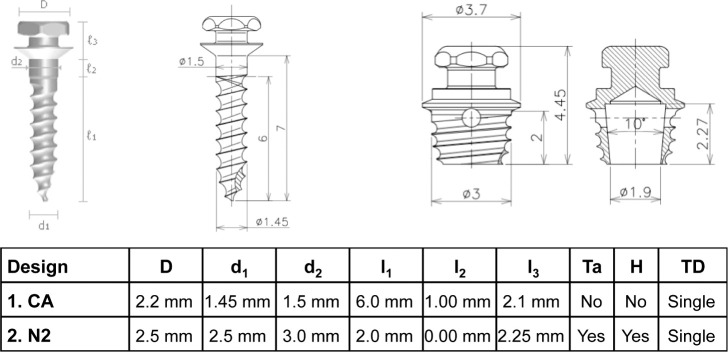
In Part 1 of this study, the N1 design was invented to address the issues of mini-implant stability and damage to nearby biological structures during implant insertion. Although the N1 design was found to enhance implant stability, it also produced high insertion torque that compromised the surrounding bone.17 In Part 2 of this study, the novel implant design N2 was introduced with revisions of reduced length, tapered shape, and tapered hollow interior (Figure 1). Results showed that the N2 design mitigated insertion torque problems, microdamage to surrounding bone, and risk of damage to anatomic structures.18 Torque and lateral displacement tests indicated the superior stability of the N2 compared with the commercially available (CA) design.
Figure 1.
Characteristics of two mini-implant designs.
Part 3 of this study introduces angulated compression and tension tests to simulate forces applied to the N2 under diverse clinical conditions. This study introduces lateral displacement tests with the application of angulated compression (pushing the implant into the bone) or angulated tension (pulling the implant out of the bone) forces on the implant neck. Compression and tension forces depend on the direction of the forces and the anatomic bony structures surrounding the mini-implant. Moreover, recent studies have demonstrated that cortical bone density is related to the success of mini-implants.19 Insertion torque has been shown to vary among different designs of mini-implants in varying bone densities.20 Because bone differs in density in the maxilla and mandible,21 torque tests were performed on varying cortical bone densities.
The aim of this study is to compare the stability and clinical applicability of the N2 with the CA design. Because bone densities as well as angulated tension and compression forces are variables in clinical applications, torque and angulated lateral displacement tests were used to assess and compare the stability of the CA design and the N2.
MATERIALS AND METHODS
According to the shape and thread design, Ti-6Al-4V alloy mini-implants (Biomaterials Korea, Seoul, Korea)18 were divided into two groups: (1) a CA design with a 1.5-mm diameter and 6-mm length and (2) the N2 with a 3-mm diameter, 2-mm length, tapered shape, and single threading.
For each test, mini-implants of each design were inserted by one technician into biosynthetic bone (Sawbones, Vashon, Wash). The bone block was composed of two layers: 2-mm thick cortical bone simulation of varying densities (20 pounds per cubic foot [pcf], 30 pcf, and 40 pcf)22 and 20-mm thick, 10-pcf trabecular bone (Table 1). A 1-mm thick acrylic sheet was used to simulate soft tissue thickness. All mini-implants were inserted perpendicular to the bone surface. The CA design was inserted until its neck made contact with the acrylic sheet. On the other hand, as the N2 is designed to be placed directly on the alveolar bone after removing overlying soft tissue via tissue punch, the acrylic sheet was not used for the N2.
Table 1.
Properties of Biosynthetic Material Simulating Cortical and Trabecular Bonea
Torque Test
As in Hong et al.,18 mini-implants (n = 20) of each design were inserted and removed using a surgical engine and contra-angle hand piece (ElcomedSA200C, W&H, Burmoos, Austria) for each cortical bone density (20 pcf, 30 pcf, and 40 pcf). The maximum insertion torque (MIT) and maximum removal torque (MRT) were measured for each insertion and removal. The unit was calibrated each time and rotation speed was set at 30 rpm.
Angulated Lateral Displacement Test
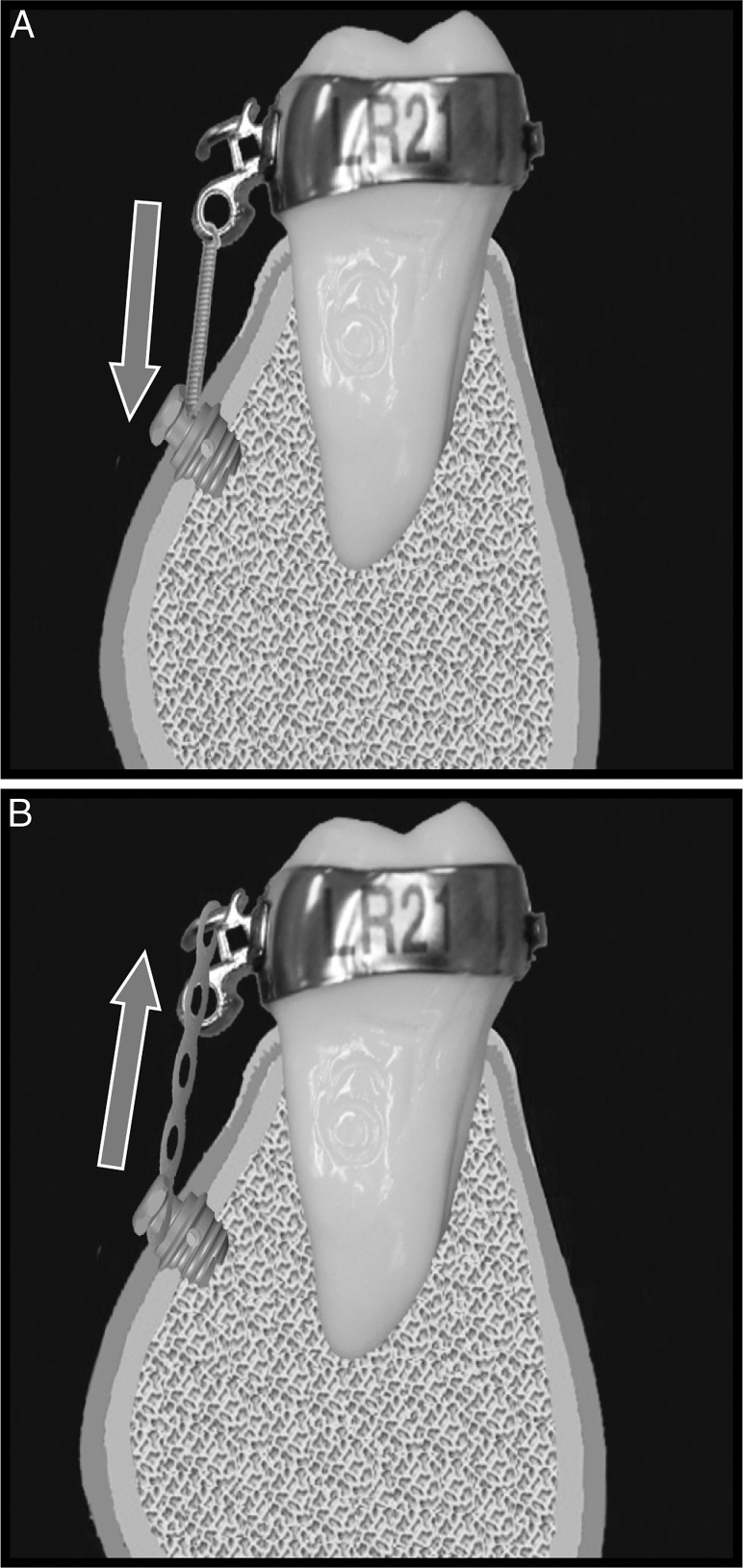
For each design, 15 new mini-implants were inserted for each angle and for both compression and tension forces (Figure 2). As in Part 2,18 after the 120 mini-implants were properly inserted using a manual driver, mechanical testing was performed using the compression mode of Instron 5560 (Instron Corporation, Norwood, Mass). With a 1 kN load cell, applied force value and lateral displacement data were computed using Bluehill 2, version 2.2, integrated software (Instron Corporation). The biosynthetic bone with mini-implants inserted was secured with the vise and positioned to allow the indenter to deliver a force perpendicular to the neck of the mini-implants. The compression and tension force vectors were applied at the four varying angles of 10°, 20°, 30°, and 40° using customized loading pins. The software recorded the force as implants were displaced from their original position at 0.01 mm, 0.02 mm, and 0.03 mm by the indenter.
Figure 2.
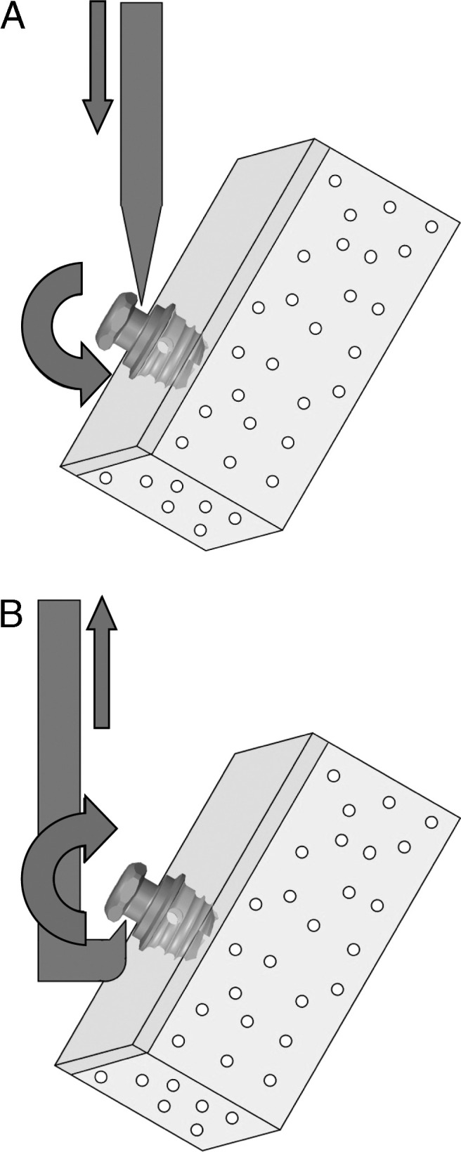
Lateral displacement force application. (A) Compression force. (B) Tension force.
Statistical Method
Mean MIT and MRT were compared across implant designs and cortical bone densities using two-way analysis of variance (ANOVA). Mean force levels for each lateral displacement distance were compared across designs and angulations using two-way ANOVA. Post hoc tests compared the two implant designs for statistical significance (α = 0.05). Intraclass correlation was used to determine intrarater reliability. Data were analyzed using Stata11 (Stata Corp LP, College Station, Tex). Means and standard deviations were reported.
RESULTS
Torque Test
The mean MIT and MRT were higher in the N2 than in the CA design at all three cortical bone densities with the exception of MRT in 20 pcf bone density, a result that was not statistically significant (Table 2). The MRT was lower than the MIT in all groups. Both the CA design and the N2 displayed increasing MIT and MRT with increasing cortical bone density, and the N2 reached a high of 19.56 Ncm MIT in 40 pcf bone density. Although the N2 displayed a steep rise in MIT in response to increased cortical bone density, the CA design showed a more gradual rise (Figure 3). Both the CA design and the N2 displayed a gradual increase of MRT with an increase in cortical bone density. For both mini-implant designs, 40 pcf cortical bone required the greatest amount of MIT and MRT.
Table 2.
Maximum Insertion Torque (MIT, Mean Ncm ± SD) and Maximum Removal Torque (MRT, Mean Ncm ± SD) of each designa
Figure 3.
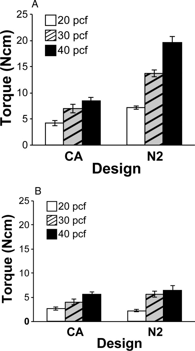
Mean measurements of (A) maximum insertion torque and (B) maximum removal torque.
Lateral Displacement Test
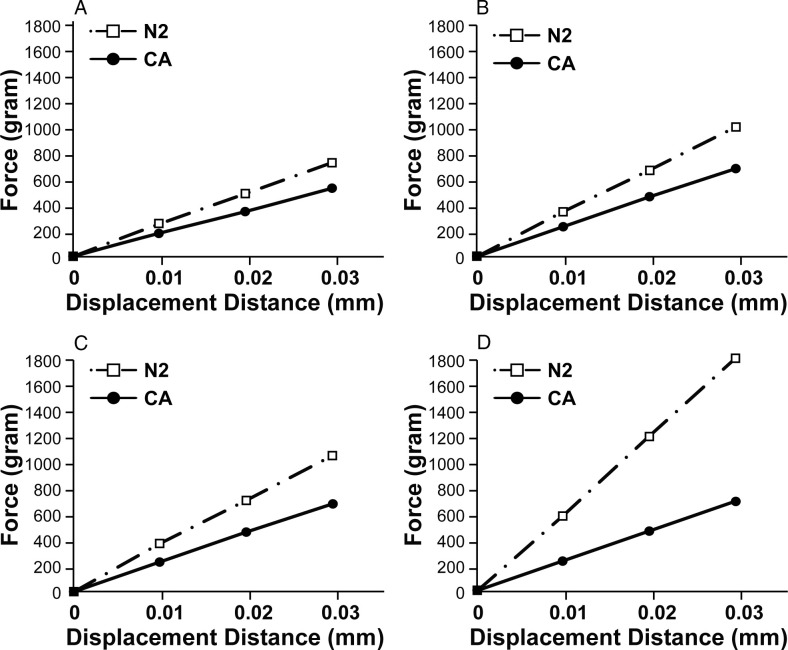
The mean compression force required to displace the N2 was greater than that required for the CA design at all distances and at all angulations (Figure 4; Table 3). As the angulation increased, the force required to displace the N2 also increased substantially. Figure 4D shows that at 40°, the N2 required a significantly greater force for displacements of 0.01, 0.02, and 0.03 mm compared to the smaller angles of 10° to 30°. This steady increase in force in response to increased angulation was not as pronounced for the CA design, which required similar or decreased force to displace it at 40°. The force required to displace the CA design 0.01 and 0.02 mm at 40° was actually reduced from 30° (Table 3).
Figure 4.
Lateral displacement summary for compression force (A) 10°, (B) 20°, (C) 30°, and (D) 40°.
Table 3.
Force Levels (Mean g ± SD) at 0.01, 0.02, and 0.03 mm Lateral Displacement of Each Design on Angulated Compression Force Vectorsa
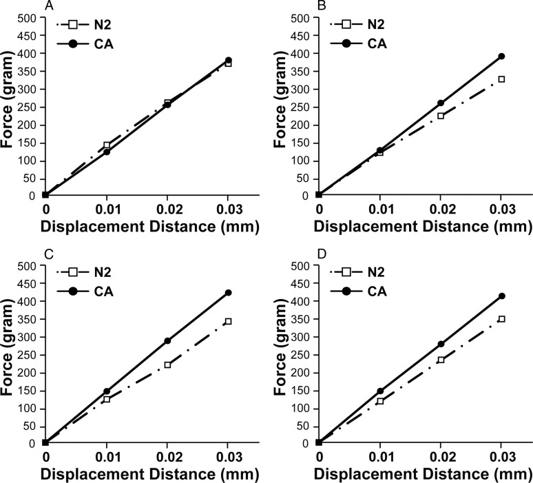
At 10°, compared to the CA design, the N2 required significantly greater mean tension force for 0.01 mm displacement (Figure 5; Table 4). The N2 required less mean tension force at 20° than at 10°, but the difference between the two angles for 0.01 mm was not statistically significant (Table 4). At angulations of 30° and 40°, the mean tension force required to displace the CA design was significantly greater at all distances. As opposed to the previous trend in compression force, the tension force needed to displace the mini-implants remained relatively constant as the angulation increased for both the CA and N2 groups (Figure 5). As previously seen in compression force, at 40° the force required to displace the CA design 0.01 and 0.02 mm was reduced from the force at 30° (Table 4). Conversely, the N2 did not show a clear pattern in mean tension force decline. However, at all displacement distances, the mean tension force required for N2 displacement was highest at a 10°, contrary to the N2 compression force requirement, which was highest at 40° for all displacement distances.
Figure 5.
Lateral displacement summary for tension force (A) 10°, (B) 20°, (C) 30°, and (D) 40°.
Table 3.
Extended.
Table 4.
Force Levels (Mean g ± SD) at 0.01, 0.02, 0.03 mm Lateral Displacement of Each Design on Angulated Tension Force Vectorsa
Table 4.
Extended.
DISCUSSION
The torque analysis data showed enhanced primary stability of the N2 compared to the CA design. Despite being shortened to avoid root proximity, MIT and MRT were higher in the N2, supporting previous studies that primary stability is not significantly affected by implant length but rather dependent on increased surface area and mechanical interlocking in cortical bone.20,23 According to linear regression analysis, a high correlation (R2 = 0.83) exists between bone density and insertion torque.24 As cortical bone density varies widely for the mandible and maxilla and for each individual, it was necessary to determine the most favorable bone density for N2 stability.
Results from this study suggest that although mini-implants should be placed in sites with adequate cortical bone density to achieve primary stability, excessive insertion torque may lead to decreased secondary stability, bone microfractures, ischemic bone necrosis, and eventually mini-implant failure.25 The mean MIT of the N2 reached as high as 19.3 Ncm in 40 pcf cortical bone density, exceeding the physiological limit of 14.65 Ncm.22 Evidently, the N2 is not ideal for insertion into areas of very high bone density.
The N2 required a significantly higher compressive force than the CA design for all displacement distances, with increasing compressive force and increasing angulations for both designs. The N2's larger diameter (3.0 mm) and enhanced mechanical interlocking with the cortical bone improved stability.18 In addition, the tapering of the N2 provided better control during insertion by reducing the wiggle effect, one of the factors associated with mini-implant failure.26 As the angle of compression force increased, the force vector directed on the N2 displaced the mini-implant into the bone, providing it with more underlying bone support against further compressive force. This increased supportive bone mass necessitates more compressive force to displace the N2 (Figure 4; Table 3).
As the N2 displayed sufficient stability to withstand compressive force as high as 1619g for 0.03 mm displacement at 40° (Table 3), it has the potential to be applied clinically for the purpose of achieving both orthodontic and orthopedic correction. In growing patients, the growth modification of facial structures with orthopedic devices is necessary to achieve skeletally balanced treatment results and to possibly avoid orthognathic surgery.27 However, conventional orthopedic devices can produce unwanted tooth movements, induce excessive stress on supporting structures, and generate issues with patient compliance.28,29 Mini-implants, with enhanced stability to withstand the forces required for orthopedic movements, have the potential to accomplish skeletal correction by applying forces directly onto skeletal structures without undesirable dental movements.8,30 If the N2 can be further modified to contain an orthopedic spring or integrated within a functional appliance apparatus for both Class II and Class III skeletal discrepancy, it is possible for the N2 to be used directly in orthopedic correction.
During the application of tension force at low angulations of 10°, the N2 displayed superior stability to the CA design. However, at higher angulations of 20–40°, the force required for N2 displacement was less than the force required for displacement of the CA design. Therefore, the tension stability threshold for the N2 exists between 10° and 20°, as the N2 requires significantly less force than the CA design for displacement at force vectors beyond 20°. A probable explanation is that tension force, unlike compression force, pulls the mini-implant away from the bone such that the decreased length of the N2 compromises the ability to withstand displacement as the angulation of the force vector increases. With less supportive bone mass with the shorter length of the N2, less tension force is required for lateral displacement (Figure 5; Table 4).
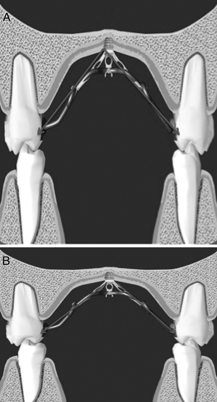
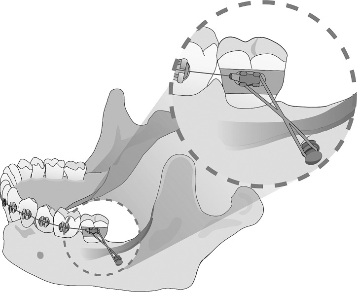
As such, the N2 can be used clinically with powerchains, coil springs, and elastics, as it can withstand light orthodontic tension and compression forces of 150–200g at all angles (Figure 6). In addition, the N2 has the potential for clinical application in conjunction with orthopedic appliances, such as headgears and face masks, if proper tubes and hooks are designed. The N2 may also be beneficial in a low palatal vault but should be avoided in regions that demand highly angulated tension forces, such as a high palatal vault, as the N2 exhibits decreased stability with higher angled tension forces (Figure 7). Advantages in the design of the N2 design may be further enhanced if consideration is given to anatomic structures and anatomic differences in each individual, as compression and tension forces can be defined relative to the location of insertion. For example, the N2 can be placed behind the external oblique ridge, to be used for mandibular molar intrusion (Figure 8), or above the maxillary anterior bulge when intrusion of the maxillary anterior is desired. In such cases, although the direction of the force may suggest a tension force, the mini-implant is actually being driven into the bone mass by a compressive force. In these situations, the N2 can be beneficial with its superior stability against angled compressive forces.
Figure 6.
Clinical applications. (A) Compression force application with open coil spring. (B) Tension force application with power chain.
Figure 7.
Placement of a mini-implant in the palate with applied angled force. (A) High palatal vault, (B) Low palatal vault.
Figure 8.
The N2 placed posterior to external oblique ridge for compressive force.
Overall, the N2 has enhanced primary stability in various clinical orthodontic applications compared with the most widely used CA design. Because of its significantly short length, the N2 has the potential to be placed superficial to root surfaces without compromising nearby anatomic structures and developing tooth buds. This superficial placement may be particularly beneficial in en masse retraction as the amount of movement is not limited by the interradicular space.31 Future clinical trials will be necessary to examine soft tissue responses and cellular processes surrounding the N2 while confirming the findings of this mechanical study.
CONCLUSION
Both torque and angulated lateral displacement tests indicate that the N2 has a superior primary stability compared to the CA design.
The N2 has promising clinical applicability for both orthodontic and orthopedic treatments, especially under compressive forces.
As the short length of the N2 reduces the risk of endangering proximal anatomic structures during placement and orthodontic treatment, the N2 design expands the number of clinically available placement sites and extends its potential usage to the mixed dentition age group.
The superior stability of the N2 may be compromised in areas of high bone density and highly angulated applications.
Future studies, including clinical trials, should be performed to examine soft tissue responses and cellular processes that surround primary and secondary stability of the N2 design.
REFERENCES
- 1.Paik CH, Park IK, Woo Y, Kim TW. Orthodontic Miniscrew Implants. Maryland Heights, MD: Mosby; 2009. pp. 8–20. [Google Scholar]
- 2.Wehrbein H, Gollner P. Skeletal anchorage in orthodontics—basics and clinical application. J Orofac Orthop. 2007;68:443–461. doi: 10.1007/s00056-007-0725-y. [DOI] [PubMed] [Google Scholar]
- 3.Young KA, Melrose CA, Harrison JE. Skeletal anchorage systems in orthodontics: absolute anchorage. A dream or reality. J Orthod. 2007;34:101–110. doi: 10.1179/146531207225022005. [DOI] [PubMed] [Google Scholar]
- 4.Sung SJ, Jang GW, Chun YS, Moon YS. Effective en-masse retraction design with orthodontic mini-implant anchorage: a finite element analysis. Am J Orthod Dentofacial Orthop. 2010;137:648–657. doi: 10.1016/j.ajodo.2008.06.036. [DOI] [PubMed] [Google Scholar]
- 5.Umemori M, Sugawara J, Mitani H, et al. Skeletal anchorage system for open-bite correction. Am J Orthod Dentofacial Orthop. 1999;115:166–174. doi: 10.1016/S0889-5406(99)70345-8. [DOI] [PubMed] [Google Scholar]
- 6.Harzer W, Schneider M, Gedrange T. Rapid maxillary expansion with palatal anchorage of the hyrzx expansion screw—pilot study with case presentation. J Orofac Orthop. 2004;65:419–424. doi: 10.1007/s00056-004-0346-7. [DOI] [PubMed] [Google Scholar]
- 7.Roberts WE, Helm FR, Marshal KJ, Gongloff RK. Rigid endosseous implants for orthodontic and orthopedic anchorage. Angle Orthod. 1990;59:247–256. doi: 10.1043/0003-3219(1989)059<0247:REIFOA>2.0.CO;2. [DOI] [PubMed] [Google Scholar]
- 8.Huang L, Shotwell JL, Wang H. Dental implants for orthodontic anchorage. Am J Orthod Dentofacial Orthop. 2004;127:713–722. doi: 10.1016/j.ajodo.2004.02.019. [DOI] [PubMed] [Google Scholar]
- 9.Bae SM, Kyung HM. Case report: mandibular molar intrusion with miniscrew anchorage. J Clin Orthod. 2006;40:107–108. [PubMed] [Google Scholar]
- 10.Roth A, Yildirim M, Diedrich P. Forced eruption with microscrew anchorage for preprosthetic leveling of the gingival margin. Case report. J Orofac Orthop. 2004;65:513–519. doi: 10.1007/s00056-004-0430-z. [DOI] [PubMed] [Google Scholar]
- 11.Yao CC, Wu CB, Wu HY, Kok SH, Chang HF, Chen YJ. Intrusion of the overerupted upper left first and second molars by mini-implants with partial-fixed orthodontic appliances: a case report. Angle Orthod. 2004;74:550–557. doi: 10.1043/0003-3219(2004)074<0550:IOTOUL>2.0.CO;2. [DOI] [PubMed] [Google Scholar]
- 12.Kuroda S, Katayama A, Takano-Yamamoto T. Severe anterior open-bite case treated using titanium screw anchorage. Angle Orthod. 2004;74:558–567. doi: 10.1043/0003-3219(2004)074<0558:SAOCTU>2.0.CO;2. [DOI] [PubMed] [Google Scholar]
- 13.Marcotte MR. Biomechanics in Orthodontics. Toronto, Canada: B. C. Decker; 1990. p. 85. [Google Scholar]
- 14.Clemmer EJ, Hayes EW. Patient cooperation in wearing orthodontic headgear. Am J Orthod. 1979;75:517–524. doi: 10.1016/0002-9416(79)90070-8. [DOI] [PubMed] [Google Scholar]
- 15.Masucci C, Franchi L, Defraia E, Mucedero M, Cozza P, Baccetti T. Stability of rapid maxillary expansion and facemask therapy: a long term controlled study. Am J Orthod Dentofacial Orthop. 2011;140:493–500. doi: 10.1016/j.ajodo.2010.09.031. [DOI] [PubMed] [Google Scholar]
- 16.Buschang PH, Carrillo R, Rossouw PE. Orthopedic correction of growing hyperdivergent, retrognathic patient with miniscrew implants. J Oral Maxillofac Surg. 2011;69:754–762. doi: 10.1016/j.joms.2010.11.013. [DOI] [PMC free article] [PubMed] [Google Scholar]
- 17.Hong C, Lee H, Webster R, Kwak J, Wu BM, Moon W. Stability comparison between commercially available miniimplants and a novel design. Angle Orthod. 2011;81:692–699. doi: 10.2319/092410-556.1. [DOI] [PMC free article] [PubMed] [Google Scholar]
- 18.Hong C, Truong P, Song HN, Wu BM, Moon W. Mechanical stability assessment of novel orthodontic mini-implant designs: part 2. Angle Orthod. 2011;81:1001–1009. doi: 10.2319/031011-176.1. [DOI] [PMC free article] [PubMed] [Google Scholar]
- 19.Park HS, Lee YJ, Jeong SJ, Kwon TG. Density of alveolar and basal bones of the maxilla and the mandible. Am J Orthod Dentofacial Orthop. 2008;133:30–37. doi: 10.1016/j.ajodo.2006.01.044. [DOI] [PubMed] [Google Scholar]
- 20.Wilmes B, Drescher D. Impact of bone quality, implant type, and implantation site preparation on insertion torques of mini-implants used for orthodontic anchorage. Int J Oral Maxillofac Surg. 2011;40:697–703. doi: 10.1016/j.ijom.2010.08.008. [DOI] [PubMed] [Google Scholar]
- 21.Choi JH, Park CH, Yi SW, Lim HJ, Hwang HS. Bone density measurement in interdental areas with simulated placement of orthodontic miniscrew implant. Am J Orthod Dentofacial Orthop. 2009;136:766.e1–766e12. doi: 10.1016/j.ajodo.2009.04.019. [DOI] [PubMed] [Google Scholar]
- 22.Chen Y, Kyung HM, Gao L, Yu WJ, Bae EJ, Kim SM. Mechanical properties of self-drilling orthodontic micro-implants with different diameters. Angle Orthod. 2010;80:821–827. doi: 10.2319/103009-607.1. [DOI] [PMC free article] [PubMed] [Google Scholar]
- 23.Motoyoshi M, Inaba M, Ono A, Ueno S, Shimizu N. The effect of cortical bone thickness on the stability of orthodontic mini-implants and on the stress distribution in surrounding bone. Int J Oral Maxillofac Surg. 2009;38:13–18. doi: 10.1016/j.ijom.2008.09.006. [DOI] [PubMed] [Google Scholar]
- 24.Wilmes B, Rademacher C, Olthoff G, Drescher D. Parameters affecting primary stability of orthodontic mini-implants. J Orofac Orthop. 2006;67:162–174. doi: 10.1007/s00056-006-0611-z. [DOI] [PubMed] [Google Scholar]
- 25.Holm L, Cunningham SJ, Petrie A, Cousley RRJ. An in vitro study of factors affecting the primary stability of orthodontic mini-implants. Angle Orthod. 2012;82:1022–1028. doi: 10.2319/011912-47.1. [DOI] [PMC free article] [PubMed] [Google Scholar]
- 26.Melsen B. Mini-implants: where are we. J Clin Orthod. 2005;39:539–547. [PubMed] [Google Scholar]
- 27.Lee KJ, Park YC, Park JY, Hwang WS. Miniscrew-assisted nonsurgical palatal expansion before orthognathic surgery for a patient with severe mandibular prognathism. Am J Orthod Dentofacial Orthop. 2010;137:830–839. doi: 10.1016/j.ajodo.2007.10.065. [DOI] [PubMed] [Google Scholar]
- 28.Travess H, Roberts-Harry D, Sandy J. Orthodontics. Part 6: risks in orthodontic treatment. Br Dent J. 2004;196:71–77. doi: 10.1038/sj.bdj.4810891. [DOI] [PubMed] [Google Scholar]
- 29.Bos A, Kleverlaan CJ, Hoogstraten J, Prahl-Andersen B, Kuitert R. Comparing subjective and objective measures of headgear compliance. Am J Orthod Dentofacial Orthop. 2007;132:801–805. doi: 10.1016/j.ajodo.2006.01.041. [DOI] [PubMed] [Google Scholar]
- 30.Baek SH, Yang IH, Kim KW, Ahn HW. Treatment of Class III malocclusion using miniplate and mini-implant anchorage. Semin Orthod. 2011;17:98–107. [Google Scholar]
- 31.Chung KR, Choo H, Kim SH, Ngan P. Timely relocation of mini-implants for uninterrupted full-arch distalization. Am J Orthod Dentofacial Orthop. 2010;138:839–849. doi: 10.1016/j.ajodo.2009.02.035. [DOI] [PubMed] [Google Scholar]


