

Abstract
Objectives:
To evaluate the influence of placement angle and direction of orthopedic force application on the stability of miniscrews.
Materials and Methods:
Finite element analysis was performed using miniscrews inserted into supporting bone at angles of 90°, 60°, and 30° (P90°, P60°, and P30°). An orthopedic heavy force of 800 gf was applied to the heads of the miniscrews in four upward (U0°, U30°, U60°, U90°) or lateral (L0°, L30°, L60°, L90°) directions. In addition, pull-out strength of the miniscrews was measured with various force directions and cortical bone thicknesses.
Results:
Miniscrews with a placement angle of 30° (P30°) and 60° (P60°) showed a significant increase in maximum von Mises stress following the increase in lateral force vectors (U30°, U60°, U90°) compared to those with a placement angle of 90° (P90°). In accordance, the pull-out strength was higher with the axial upward force when compared to the upward force with lateral vectors. Maximum von Mises stress and displacement of the miniscrew increased as the angle of lateral force increased (L30°, L60°, L90°). However, a more dramatic increase in maximum von Mises stress was noted in P30° than in P60° and P90°.
Conclusion:
Placement of the miniscrew perpendicular to the cortical bone is advantageous in terms of biomechanical stability. Placement angles of less than 60° can reduce the stability of miniscrews when orthopedic forces are applied in various directions.
Keywords: Miniscrew, Stability, Intermaxillary traction, Finite element modeling, Pull-out test
INTRODUCTION
Temporary anchorage devices (TADs) have provided efficient skeletal anchorage for tooth movement. Clinically, the successful use of TADs depends greatly on stability. Most studies report a success rate with TADs above 80%, and TADs are now commonly accepted as a simple and effective tool for daily orthodontic practice.1
TADs are used not only for conventional tooth movement, but in recent years, they have also been used in the application of dentofacial orthopedics. A wider range of TAD applications has been introduced, such as anchorage for orthopedic traction using intermaxillary elastics,2–5 anchorage for face masks to correct skeletal Class III crossbite,6,7 assistance with rapid palatal expansion of the maxilla in adults,8,9 and anchorage for intermaxillary fixation following various reduction and orthognathic surgeries.
Recently, bone-anchored Class III intermaxillary traction was applied to Class III adolescents; this reportedly induced three-dimensional changes in the mandible and the glenoid fossa.3,5,10 Although miniplates were used in these studies, biomechanically, miniscrews may also provide similar results when combined with elastics. In cases of orthopedic correction, especially when interarch elastics are attached to the miniscrew, it can be speculated that higher force magnitudes are delivered to the miniscrew because additional forces are created from functional jaw movements generated during protrusive, retrusive, and lateral movements of the mandible. However, reports on the stability and success rates of miniscrews are, for the most part, limited to orthodontic tooth movements; thus, mobility with applied forces ranging from 100g to 400g have been evaluated,1 and these forces tend to decrease with tooth movement. In addition to the intermittent increases in force magnitude exerted by intermaxillary elastics, forces are loaded to the miniscrews in multiple directions during functional jaw movements. Lateral, torsional, shear, and extrusive forces that are not recommended in the conventional setting of orthodontic tooth movement11 are inevitable during jaw movements, possibly threatening miniscrew stability.
Finite element analysis (FEA) is a useful and flexible approach to evaluate stress distribution in dental biomechanics.12,13 Recently, various finite element models (FEM) have been developed to address mechanical factors involved in the stability of miniscrews. The changes in stress distribution with various placement angles and load directions have shown that most miniscrews have enough strength to resist orthodontic loads under 2 N.13 However, limited information is available concerning higher force magnitudes. It can be speculated that there would be an increase in stress level with higher force magnitudes because stress is almost linearly proportional to force magnitude when a miniscrew is placed perpendicular to the cortical bone.12 But, as seen in clinical situations, different placement angles or loading orientations can induce changes in the maximum force that a miniscrew can withstand, leading to instability.14,15
Therefore, the aim of this study was to examine the possibilities and risks of applying orthopedic forces to miniscrews in various clinical settings. The effect of applying heavy orthopedic forces at different placement angles and loading orientations was compared using FEA in combination with pull-out tests.
MATERIALS AND METHODS
An FEM of the supporting bone was constructed as an 11- × 15-mm cylinder with 1 mm of cortical bone and 10 mm of cancellous bone using SolidWorks 2006, a computer-aided design program (Solid Works, Concord, Mass). The miniscrew design was based on a combination-type scheme with cylindrical and tapered portions (Orlus 1H1610, Ortholution, Seoul, Korea). The model consisted of 116,447 elements and 159,890 nodes. The bone and miniscrews were assumed to be isotropic, homogeneous, and linearly elastic. The mechanical properties included Young's moduli of 1.5 × 10⁴ MPa, 1.5 × 10³ MPa, and 1.05 × 10⁵ MPa and Poisson ratios of 0.30, 0.30, and 0.33, respectively, for cortical bone, cancellous bone, and miniscrews.16,17 Miniscrews were placed at three different angles (α) to the cortical bone surface: 90°, 60°, and 30° (P90°, P60°, P30°) (Figure 1A). Vertical upward forces were applied to the head structure in an ascending order of 30° to the z-axis (Figure 1B), and lateral forces were applied in an ascending order of 30° to the x-axis (Figure 1C).
Figure 1.
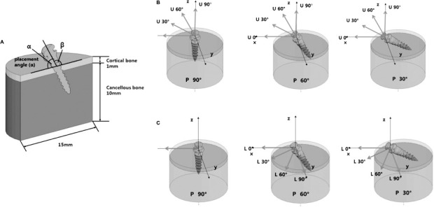
Schematic illustrations of the finite element model with its placement angles and the loading conditions. (A) An FEM was constructed with cortical and cancellous bone, and a combination-type miniscrew was inserted at various angles (α). (B) Loading conditions of the vertical upward forces in an ascending order of 30° to the z-axis (U0°, U30°, U60°, U90°). (C) Loading conditions of the lateral forces in an ascending order of 30° to the x-axis (L0°, L30°, L60°, L90°).
Unlike orthodontic forces, a higher force range of approximately 300–500 gf is typical of conventional orthopedic forces. When intermaxillary elastics are applied for orthopedic movement, they may induce an additional 104–374 gf during wide mouth opening.18 Therefore, we set our force level at 800 gf during this investigation. The maximum von Mises stress of the bone around the miniscrew and the displacement of the miniscrew were also examined. The stress distribution within the surrounding bone and displacement of the miniscrew were visualized as colors ranging from blue (lowest/least) to red (highest/most).
Bone simulants were used for the pull-out tests. For test materials, E-glass–filled epoxy sheets (density of 1.7 g/cc, compressive strength of 120 MPa, tensile strength of 90 MPa) were used to simulate cortical bone, whereas solid rigid polyurethane foam (density of 0.48 g/cc, compressive strength of 18 MPa, tensile strength of 12 MPa) was used to mimic trabecular bone. Two types of artificial bone specimens with 0.5 mm and 1.0 mm of cortical bone thickness were fabricated and miniscrews were inserted perpendicular to the bone block as mentioned previously.19 The bone specimens were divided into eight groups according to the direction of force (0°, 30°, 60°, 90°) and cortical bone thickness (0.5 mm, 1.0 mm). A customized jig was designed to adjust the direction of force application to the miniscrew (Figure 2). A 0.5- × 0.5-mm rectangular wire was connected to the upper hole in the miniscrew. A crosshead speed of 0.05 mm per second was applied until the miniscrew was extruded from the bone specimen, and the maximum tensile load value N was recorded using a universal testing machine (Instron 3366, Instron, Norwood, Mass).
Figure 2.
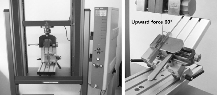
Specialized jig system for the application of directional pull-out forces.
Statistical Analysis
To identify the differences in the maximum tensile load according to the pull-out direction of each specimen with different cortical thicknesses, a one-way analysis of variance was performed. Then, the Tukey studentized rank test was used for post hoc analysis. All analyses were performed using SPSS/WIN 18.0 (SPSS Inc, Chicago, Ill) at significance levels of P < .05.
RESULTS
Depending on the force application, the stress was focused at the edges of the screw threads in the cortical bone region rather than in the cancellous region (Figure 3A). Vertical forces applied parallel to the miniscrew's long axis resulted in a broad distribution of stresses throughout the cortical bone/miniscrew interface and tended to result in lower maximum von Mises stresses (Figure 3A, j, h, f) and miniscrew displacement (Figure 3B, j, h, f) compared to upward forces with lateral vectors, regardless of the miniscrew's placement angle. When the applied force was not parallel to the miniscrew's insertion axis, the stress was most intense in the region of the cortex adjoining the miniscrew in the direction of the force, which also contributed to maximum displacement. Miniscrews with placement angles of 30° (P30°) and 60° (P60°) showed especially significant increases in maximum von Mises stresses following an increase in lateral force vectors (U30°, U60°, U90°) in comparison to P90° (Figure 4).
Figure 3.
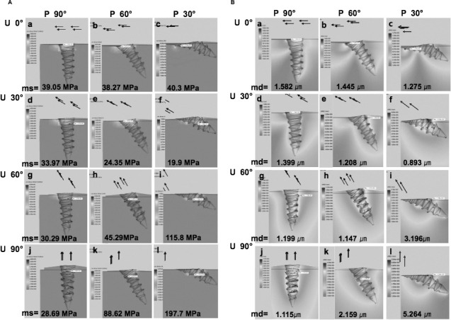
Comparisons of stress distribution and displacement according to the placement angle and upward force. (A) Stress distribution and maximum von Mises stress (MPa). (B) Displacement and maximum displacement (µm). Arrows indicate the direction of force application regardless of the number of arrows; ms, maximum von Mises stress; and md, maximum displacement.
Figure 4.
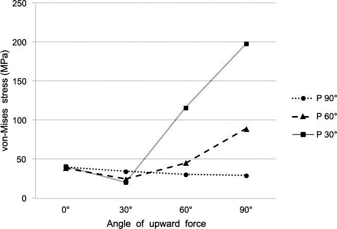
Maximum von Mises stress (MPa) according to placement angle and upward force.
Stress distribution and displacement were also influenced by the changes in lateral force. Following the increase in the lateral force angle, the stress and displacement also tended to increase on the compression side (Figure 5A,B). In particular, miniscrews with a placement angle of 30° (P30°) showed significant increases in maximum von Mises stress corresponding to the increase of lateral force compared to the steady state of P60° or P90° (Figure 6).
Figure 5.
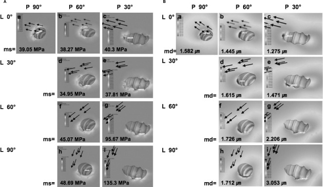
Comparisons of stress distribution and displacement according to the placement angle and lateral force. (A) Stress distribution and maximum von Mises stresses (MPa). (B) Displacement and maximum displacement (µm). Arrows indicate the direction of force application regardless of the number of arrows; ms, maximum von Mises stress; md, maximum displacement.
Figure 6.
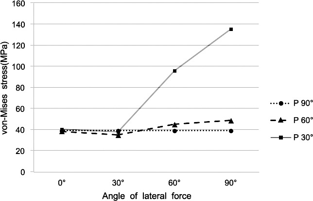
Maximum von Mises stress (MPa) according to placement angle and lateral force.
The pull-out strength was highest when the vertical pull-out force was applied parallel to the insertion axis (pure vertical, 90°). It gradually lessened as the lateral force vector increased from a parallel to perpendicular force and was lowest when the force was perpendicular to the insertion axis (pure lateral force, 0°). Furthermore, an increase in cortical bone thickness from 0.5 to 1.0 mm significantly increased the pull-out strength (P < .05) (Table 1).
Table 1.
Pull-out strength according to the upward force and the cortical bone thickness

DISCUSSION
The primary stability of miniscrews is a result of mechanical interlocking of the threads with cortical bone.20 However, even if initial stability is accomplished, overload to the adjacent bone may interfere with the physiological remodeling of the bone-screw interface, resulting in later failure. Loads above 4000 µ-strain may threaten the structural integrity of the bone, resulting in pathologic overload21,22 and inducing fibrous healing at the implant-bone interface.23 A load of 4000 µ-strain is converted to 55 MPa of compressive stress in the cortical bone.24 According to our FEM study, the maximum von Mises stress was consistently below 55 MPa when the miniscrew was placed perpendicular to the cortical bone (P90°), regardless of the direction of orthopedic force application. On the other hand, maximum von Mises stress increased dramatically as the degrees of lateral and vertical force application increased in miniscrews placed at an angle of 30° (P30°) and to a lesser degree in the P60° group, far exceeding 55 MPa and reaching up to 200 MPa, which is the yield strength of cortical bone.25 Some studies have suggested that the placement of a miniscrew at an angle to the bone surface increases cortical bone contact and placement torque, resulting in a positive effect on miniscrew stability when orthodontic forces are applied.20,26,27 In contrast, others have recommended placing miniscrews at 90° to the bone surface for optimum retention, while indicating that placement angles less than 90° potentially create longer lever arms, reducing anchorage resistance so that failure can occur even within orthodontic force levels.14,28 Based on our results and those of previous studies, we recommend placement of the miniscrew perpendicular to the cortical bone (P90°) as long as root damage can be avoided to take advantage of improved biological and biomechanical stability when applying heavy orthopedic forces.
In addition to investigating insertion variables using the FEA, we also examined the effects of various loading directions and cortical bone thickness using the pull-out test. Pull-out strength increased significantly when cortical bone thickness doubled from 0.5 to 1.0 mm, but in young adolescents, who make up the majority of patients treated with orthopedics, the cortical thickness is sometimes less than 1 mm.29 Thin cortical bone can cause stability issues because the stresses are localized mainly to the cortical bone region. Although we were only able to test the effects of force direction with our pull-out model, the test results using miniscrews at various insertion angles also advocate perpendicular insertion,14 as do our FEM results.
In general, TADs are not loaded vertically in clinical situations, since orthodontic retraction forces usually induce stable horizontal/lateral forces to the TAD parallel to the occlusal plane.14 However, when orthopedic forces are applied to TADs, mandibular movement during maxillofacial functions such as speech, breathing, etc, may apply intermittent forces to the TADs three-dimensionally to varying degrees, leading to additional fatigue. Future studies using models that simulate the dynamics of the jaw may provide broader clinical guidance for the placement and stability of TADs.
CONCLUSIONS
Miniscrews placed at angles of less than 60° showed a significant increase in maximum von Mises stress following an increase in lateral force vectors compared to miniscrews placed perpendicular to the bone.
An increase in cortical bone thickness from 0.5 to 1.0 mm significantly increased the pull-out strength of the miniscrew.
Based on our results, we recommend placement of miniscrews perpendicular to cortical bone to take advantage of biological and biomechanical stability when applying heavy orthopedic forces.
Acknowledgments
This study was sponsored by the faculty research grant of Yonsei University, College of Dentistry 2011-0059. We thank Mr Moo-Seok Bahng for his help designing the FEM. FEM and Mr Deokchang Lee, Biomaterials Korea, for his help on the pull-out test.
REFERENCES
- 1.Reynders R, Ronchi L, Bipat S. Mini-implants in orthodontics: a systematic review of the literature. Am J Orthod Dentofacial Orthop. 2009;135(5):564.e1–19; discussion 564–565. doi: 10.1016/j.ajodo.2008.09.026. [DOI] [PubMed] [Google Scholar]
- 2.Nguyen T, Cevidanes L, Cornelis MA, Heymann G, de Paula LK, De Clerck H. Three-dimensional assessment of maxillary changes associated with bone anchored maxillary protraction. Am J Orthod Dentofacial Orthop. 2011;140:790–798. doi: 10.1016/j.ajodo.2011.04.025. [DOI] [PMC free article] [PubMed] [Google Scholar]
- 3.De Clerck HJ, Cornelis MA, Cevidanes LH, Heymann GC, Tulloch CJ. Orthopedic traction of the maxilla with miniplates: a new perspective for treatment of midface deficiency. J Oral Maxillofac Surg. 2009;67:2123–2129. doi: 10.1016/j.joms.2009.03.007. [DOI] [PMC free article] [PubMed] [Google Scholar]
- 4.Jamilian A, Showkatbakhsh R. Treatment of maxillary deficiency by miniscrew implants—a case report. J Orthod. 2010;37:56–61. doi: 10.1179/14653121042876. [DOI] [PubMed] [Google Scholar]
- 5.De Clerck H, Cevidanes L, Baccetti T. Dentofacial effects of bone-anchored maxillary protraction: a controlled study of consecutively treated Class III patients. Am J Orthod Dentofacial Orthop. 2010;138:577–581. doi: 10.1016/j.ajodo.2009.10.037. [DOI] [PMC free article] [PubMed] [Google Scholar]
- 6.Kircelli BH, Pektas ZO. Midfacial protraction with skeletally anchored face mask therapy: a novel approach and preliminary results. Am J Orthod Dentofacial Orthop. 2008;133:440–449. doi: 10.1016/j.ajodo.2007.06.011. [DOI] [PubMed] [Google Scholar]
- 7.Enacar A, Giray B, Pehlivanoglu M, Iplikcioglu H. Facemask therapy with rigid anchorage in a patient with maxillary hypoplasia and severe oligodontia. Am J Orthod Dentofacial Orthop. 2003;123:571–577. doi: 10.1067/mod.2003.S0889540603000520. [DOI] [PubMed] [Google Scholar]
- 8.Lee KJ, Park YC, Park JY, Hwang WS. Miniscrew-assisted nonsurgical palatal expansion before orthognathic surgery for a patient with severe mandibular prognathism. Am J Orthod Dentofacial Orthop. 2010;137:830–839. doi: 10.1016/j.ajodo.2007.10.065. [DOI] [PubMed] [Google Scholar]
- 9.Kircelli BH, Pektas ZO, Uckan S. Orthopedic protraction with skeletal anchorage in a patient with maxillary hypoplasia and hypodontia. Angle Orthod. 2006;76:156–163. doi: 10.1043/0003-3219(2006)076[0156:OPWSAI]2.0.CO;2. [DOI] [PubMed] [Google Scholar]
- 10.De Clerck H, Nguyen T, de Paula LK, Cevidanes L. Three-dimensional assessment of mandibular and glenoid fossa changes after bone-anchored Class III intermaxillary traction. Am J Orthod Dentofacial Orthop. 2012;142:25–31. doi: 10.1016/j.ajodo.2012.01.017. [DOI] [PMC free article] [PubMed] [Google Scholar]
- 11.Cheng SJ, Tseng IY, Lee JJ, Kok SH. A prospective study of the risk factors associated with failure of mini-implants used for orthodontic anchorage. Int J Oral Maxillofac Implants. 2004;19:100–106. [PubMed] [Google Scholar]
- 12.Liu TC, Chang CH, Wong TY, Liu JK. Finite element analysis of miniscrew implants used for orthodontic anchorage. Am J Orthod Dentofacial Orthop. 2012;141:468–476. doi: 10.1016/j.ajodo.2011.11.012. [DOI] [PubMed] [Google Scholar]
- 13.Suzuki A, Masuda T, Takahashi I, Deguchi T, Suzuki O, Takano-Yamamoto T. Changes in stress distribution of orthodontic miniscrews and surrounding bone evaluated by 3-dimensional finite element analysis. Am J Orthod Dentofacial Orthop. 2011;140:e273–280. doi: 10.1016/j.ajodo.2011.06.025. [DOI] [PubMed] [Google Scholar]
- 14.Petrey JS, Saunders MM, Kluemper GT, Cunningham LL, Beeman CS. Temporary anchorage device insertion variables: effects on retention. Angle Orthod. 2010;80:446–453. doi: 10.2319/070309-376.1. [DOI] [PMC free article] [PubMed] [Google Scholar]
- 15.Pickard MB, Dechow P, Rossouw PE, Buschang PH. Effects of miniscrew orientation on implant stability and resistance to failure. Am J Orthod Dentofacial Orthop. 2010;137:91–99. doi: 10.1016/j.ajodo.2007.12.034. [DOI] [PubMed] [Google Scholar]
- 16.Stegaroiu R, Sato T, Kusakari H, Miyakawa O. Influence of restoration type on stress distribution in bone around implants: a three-dimensional finite element analysis. Int J Oral Maxillofac Implants. 1998;13:82–90. [PubMed] [Google Scholar]
- 17.Geng JP, Tan KB, Liu GR. Application of finite element analysis in implant dentistry: a review of the literature. J Prosthet Dent. 2001;85:585–598. doi: 10.1067/mpr.2001.115251. [DOI] [PubMed] [Google Scholar]
- 18.Kanchana P, Godfrey K. Calibration of force extension and force degradation characteristics of orthodontic latex elastics. Am J Orthod Dentofacial Orthop. 2000;118:280–287. doi: 10.1067/mod.2000.104493. [DOI] [PubMed] [Google Scholar]
- 19.Song YY, Cha JY, Hwang CJ. Mechanical characteristics of various orthodontic mini-screws in relation to artificial cortical bone thickness. Angle Orthod. 2007;77:979–985. doi: 10.2319/090606-363.1. [DOI] [PubMed] [Google Scholar]
- 20.Miyawaki S, Koyama I, Inoue M, Mishima K, Sugahara T, Takano-Yamamoto T. Factors associated with the stability of titanium screws placed in the posterior region for orthodontic anchorage. Am J Orthod Dentofacial Orthop. 2003;124:373–378. doi: 10.1016/s0889-5406(03)00565-1. [DOI] [PubMed] [Google Scholar]
- 21.Frost HM. Bone “mass” and the “mechanostat”: a proposal. Anat Rec. 1987;219:1–9. doi: 10.1002/ar.1092190104. [DOI] [PubMed] [Google Scholar]
- 22.Frost HM. Bone's mechanostat: a 2003 update. Anat Rec A Discov Mol Cell Evol Biol. 2003;275:1081–1101. doi: 10.1002/ar.a.10119. [DOI] [PubMed] [Google Scholar]
- 23.Meyer U, Joos U, Mythili J, et al. Ultrastructural characterization of the implant/bone interface of immediately loaded dental implants. Biomaterials. 2004;25:1959–1967. doi: 10.1016/j.biomaterials.2003.08.070. [DOI] [PubMed] [Google Scholar]
- 24.Nam O, Yu W, Kyung H. Cortical bone strain during the placement of orthodontic microimplant studied by 3D finite element analysissis. Korean J Orthod. 2008;38:228–239. [Google Scholar]
- 25.Ebacher V, Tang C, McKay H, Oxland TR, Guy P, Wang R. Strain redistribution and cracking behavior of human bone during bending. Bone. 2007;40:1265–1275. doi: 10.1016/j.bone.2006.12.065. [DOI] [PubMed] [Google Scholar]
- 26.Wilmes B, Su YY, Drescher D. Insertion angle impact on primary stability of orthodontic mini-implants. Angle Orthod. 2008;78:1065–1070. doi: 10.2319/100707-484.1. [DOI] [PubMed] [Google Scholar]
- 27.Deguchi T, Nasu M, Murakami K, Yabuuchi T, Kamioka H, Takano-Yamamoto T. Quantitative evaluation of cortical bone thickness with computed tomographic scanning for orthodontic implants. Am J Orthod Dentofacial Orthop. 2006;129:721.e727–712. doi: 10.1016/j.ajodo.2006.02.026. [DOI] [PubMed] [Google Scholar]
- 28.Woodall N, Tadepalli SC, Qian F, Grosland NM, Marshall SD, Southard TE. Effect of miniscrew angulation on anchorage resistance. Am J Orthod Dentofacial Orthop. 2011;139:e147–152. doi: 10.1016/j.ajodo.2010.08.017. [DOI] [PubMed] [Google Scholar]
- 29.Farnsworth D, Rossouw PE, Ceen RF, Buschang PH. Cortical bone thickness at common miniscrew implant placement sites. Am J Orthod Dentofacial Orthop. 2011;139:495–503. doi: 10.1016/j.ajodo.2009.03.057. [DOI] [PubMed] [Google Scholar]