

Abstract
Natural biomolecular self-assembly typically occurs under a narrow range of solution conditions, and the design of sequences that can form prescribed structures under a range of such conditions would be valuable in the bottom-up assembly of predetermined nanostructures. We present a computationally designed peptide that robustly self-assembles into regular arrays under a wide range of solution pH and temperature conditions. Controling the solution conditions provides the opportunity to exploit a simple and reproducible approach for altering the pathway of peptide solution self-assembly. The computationally designed peptide forms a homotetrameric coiled-coil bundle that further self-assembles into 2-D plate structures with well-defined inter-bundle symmetry. Herein, we present how modulation of solution conditions, such as pH and temperature, can be used to control the kinetics of the inter-bundle assembly and manipulate the final morphology. Changes in solution pH primarily influence the inter-bundle assembly by affecting the charged state of ionizable residues on the bundle exterior while leaving the homotetrameric coiled-coil structure intact. At low pH, repulsive interactions prevent 2-D lattice nanostructure formation. Near the estimated isoelectric point of the peptide, bundle aggregation is rapid and yields disordered products, which subsequently transform into ordered nanostructures over days to weeks. At elevated temperatures (T = 40°C or 50°C), the formation of disordered, kinetically-trapped products largely can be eliminated, allowing the system to quickly assemble into plate-like nanostructured lattices. Moreover, subtle changes in pH and in the peptide charge state have a significant influence on the thickness of formed plates and on the hierarchical manner in which plates fuse into larger material structures with observable grain boundaries. These findings confirm the ability to finely tune the peptide assembly process to achieve a range of engineered structures with one simple 29-residue peptide building block.
Graphical Abstract
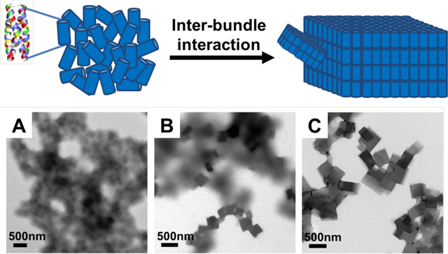
This work is showing the ability to control the kinetics of peptide assembly while leaving both the designed α-helical and tetrameric helical bundle intact.
Introduction
Efforts in nanomaterial construction via solution-phase self-assembly recently have focused on nanostructure complexity and controllability.1–19 For example, block copolymer assembly has been successfully employed to yield controlled complexity of nanoparticle shape and size via hierarchical assembly mechanisms.17,20–24 The application of a kinetic assembly pathway and/or chemical modification of assembling molecules can trigger desired interactions between block copolymers21,22 or can induce crystallization-driven self-assembly with crystalline-coil diblock copolymers to produce targeted, kinetically-defined morphologies.16,18,24 Molecules with specific architectures and desired display of chemical groups have also been used to control intermolecular assembly. For example, by placing different silsesquioxane molecules onto rigid carbon frameworks, the resultant molecules can self-assemble into highly ordered superlattices.2,3 With control of biomimetic polymer sequence, designed peptoid molecules can produce ordered structures such as nano-sheets or porous nano-networks.25–29 Biomolecules represent an exceptionally versatile set of building blocks that can yield complex assembled nanostructures, including nucleic acids (DNA and RNA), peptides and proteins. The folded states of these biopolymers allow inherent specificity of local chemical functionality and its display due to exact primary, secondary, tertiary and intermolecular quaternary structures. The specific base-pairing interactions of nucleic acids, which drive their natural hierarchical organization, allow computational design to create new, non-natural sequences and resultant nanostructure after solution assembly.7,8,30 Self-assembled DNA/RNA nanostructures can be controlled at the nanoscale exclusively through the proper design of complementary base pairing, which has enabled the production of complex structures,7,8 the templating of other molecules onto the nucleic acid-based nanostructure,31–34 and the performance of simple computational functions.35–38
Peptides and proteins share similar features with polymeric nucleic acids in that they can form well-defined molecular conformations containing regular secondary structures defined by the primary sequence of monomers—a stark difference in conformational properties when compared with the random coil conformations of most synthetic polymers.39,40 Peptide or protein molecular shape can be considered as a key parameter in the design of intermolecular assemblies, both on the basis of geometric considerations and also by virtue of the installation of directed, local covalent or physical interactions that allow the construction of nanostructures in a controllable fashion. Moreover, the 20 naturally occurring amino acids provide a variety of different side-chain functional groups making peptides/proteins much more versatile chemically when compared with nucleic acids. This versatility becomes almost limitless when considering designs that incorporate non-natural, synthetic amino acids.41–44 The advent of computational design is quickly advancing the creation of new peptide or protein-based nanostructures. Examples include the alteration of natural proteins for desired intermolecular assembly such as protein nanohedra,45–47 periodic assemblies of helical proteins,48–52 and fibers, lattices and cages produced by redesigning natural protein interfaces.10,14,53,54
Different assembly products can be kinetically trapped in reproducible fashion with different assembly pathways. In block copolymer systems, kinetic trapping is due to slow or non-existent chain exchange between aggregates and solvent.20,21,55 Other examples include π-conjugated systems, such as oligo(p-phenylenevinylene) derivatives, for which a hierarchical nucleation pathway, assisted by solvent, dictated final assembled structures.56 Additionally, small molecules, such as self-assembled bis(merocyanine) nanorods, exhibit a time-dependent stereomutation from a product of a fast kinetic pathway of formation to a more stable product.57 Kinetically-defined assembly pathways have clear effects in peptide- and protein-based assemblies such as the slow morphology transition from ribbons to β-helices in myeloid-derived peptide segments, driven in part by reorganization of molecular packing.58 Thermal pathways can drive nanofibers formed by peptide amphiphiles to fuse into stronger plaque-like structures.59 A variety of protein assembly products with different morphologies can result from different nucleation rates affected by pH and metal/protein ratios.60
Herein we present nanostructures produced by the assembly of peptide building blocks that are entirely computationally designed50 rather than derived from existing, natural protein-based motifs or templates. This approach provides design flexibility for the creation of non-natural, arbitrary nanostructures. Our assembly system uses a homotetrameric, antiparallel coiled-coil peptide bundle as the building block for hierarchical solution assembly.61 The interior of the bundle consists primarily of complementary hydrophobic amino acids that provide for high stability of the bundle. Using the stable hydrophobic core as a basis for additional design, the amino acids on the exterior of the bundle were computationally designed to stabilize a 2-D lattice formed by inter-bundle solution assembly.61 Due to the robust design, the peptide building blocks are able to maintain the α-helical secondary structure and coiled-coil quaternary structure in solutions very different from common physiological conditions. Therefore, a significantly larger range of solution conditions can be employed to explore the effects of different intermolecular assembly pathways on nanostructure formation. Kinetic pathways may be designed and used in the self-assembly process to create complex assemblies.21,56,57,59,60,62
As mentioned, our designed peptide tetrameric bundle need not be constrained to assemble in physiological solution conditions but can tolerate variation of pH and temperature. In this work, a variety of solution condition parameters (pH = 4.5, 7, 8 or 10; T = room temperature, 40°C or 50°C) were applied as assembly solution conditions to investigate the formation of the tetrameric bundle building block and resultant inter-bundle structures. This control includes the ability to control regular inter-bundle assembly and the reorganization of disordered aggregates into ordered plate-like nanomaterials, where the rate of re-organization is dictated by solution temperature. With the use of computationally designed, non-natural peptide bundles, the control of kinetic pathways through manipulation of non-biological solution conditions offers new opportunities to process and anneal nanostructures into a desired assembly state.
Results and discussion
The peptide sequence studied here was originally designed to form a tetrahelical bundle that further assembles into a 2-D plate-like nanostructure (Figure S1). The sequence (DQEIR QMAEW IKKMA QMIDK MAHRI DREA-NH2) was computationally designed de novo to form a robust homotetrameric coiled-coil.61 The backbone structure of the coiled-coil tetramer bundle was identified using a mathematical model for coiled-coils,63 and the structure contains eleven interior residues per helix that were specified as hydrophobic amino acids and achieve shape-complementary packing within the tetramer interior. The remaining, surface-exposed residues were designed in the context of a single-layer of a P422 lattice. The probabilistic design method provides an average energy over sequences for a given structure,50 and the designed peptide falls in a local energy minimum. The investigated variant with the N-terminus acetylated had an estimated pI = 8.12 (sequence information in Supplementary Information). The models of the designed hierarchical assembled structure are given in Figure 1.
Figure 1.

A: The assembly building block is a cylinder-like peptide homotetrameric coiled-coil bundle. (The exterior residues are colored according to amino acid properties: blue indicates positively charged residues, red indicates negatively charged residues, green indicates polar residues, and yellow indicates hydrophobic residues. Interior residues are colored grey). B-C: The tetrameric bundles (represented by cylinders), through inter-bundle interactions, further assemble into plate-like nanostructures, predominately in 2-D.
Buffer systems with pH values of 4.5, 7, 8 and 10 were used to investigate the assembly behaviour. From the circular dichroism spectra of peptides in buffers with these pH values (Figure S4), it was clear that the peptides maintained ellipticity minima consistent with those for α-helical structures (208 and 222 nm) for each pH condition. Furthermore, the measured ratios of [θ]222nm/[θ]208nm for each of the peptide solutions are close to 1, consistent with reported values of stabilized coiled-coils.64,65 These results reveal the tolerance of this tetrameric coiled-coil to a broad range of pH conditions, attributable to the robust computational design of a peptide with strong α-helix propensity and a stable hydrophobic coiled-coil core. Although the homotetrameric building blocks were formed, the hierarchical 2-D assembly observed under the different pH conditions varied considerably depending on the pH. When assembled at pH 4.5, the peptide coiled-coil bundles remained free in solution (peptide concentration from 0.1 mM to 1 mM) without any formation of aggregates or regular 2-D nanostructures (data not shown). At pH 7 and pH 8, peptide bundles aggregated rapidly and formed visible precipitates from solution within the first several hours, even at concentrations as low as 0.1 mM. After subsequent weeks of aging, these same solution conditions provided very regular assembled nanostructures (shown in Figure 2, discussed vide infra). At pH 10, in contrast, regular 2-D nanostructures were formed only at high concentration (1 mM) and only after long assembly times (>2 months).61
Figure 2.

Transmission electron microscopy images of designed sequence assembled at RT and observed at different time periods. A-C: Peptides assembled at RT pH 8 for 2 days, 1 week and 8 weeks, respectively. D-F: Peptides assembled at RT pH 7 for 2 days, 1 week and 8 weeks, respectively. Both cases show disordered aggregates that formed at earlier time points and then transformed into ordered 2-D plates after aging.
As described earlier, the tetrameric coiled-coil bundle is mainly stabilized by the hydrophobic core while the hierarchical lattice assemblies are stabilized by the inter-bundle interactions through positioning of select amino acid residues at the exterior positions. This peptide sequence has 13 ionizable residues (sequence information in Supplementary Information), and control of the charged states of these residues can be mediated by solution pH. This design affords control of the kinetics of the inter-bundle assembly process by tuning the inter-bundle interaction from repulsive to attractive (and more finely tuned to yield assembly or aggregation) all while leaving the basic homotetrameric building block intact. Therefore, the observed assembly behaviour can be rationalized by the estimated charge per bundle at different pH values, based on individual amino acid side chain pKa values (described in the Supplementary Information).66 At pH 4.5, each peptide carries a positive net charge of approximately Z = +3 with the tetrameric bundle having a net charge of approximately Z = +12. This strong electrostatic repulsive interaction disrupts inter-bundle assembly and precludes the formation of regular nanostructure. Importantly, the coiled-coil design is stable enough that bundles still formed at this pH (Figure S4) despite not undergoing further, hierarchical assembly. At pH 7 and pH 8, each bundle is expected to carry either a slightly positive charge (approximately Z = +1 at pH 7) or to be neutral (Z = 0 at pH 8). Due to the relatively small effective net charge, the peptides aggregated most rapidly in pH 7 and pH 8 buffer. At pH 10, each bundle has Z = −2, which destabilized the inter-bundle assembly to some extent relative to pH 7 or pH 8. At pH 10, inter-bundle assemblies could still be achieved, but the assembly process was significantly hindered and slow.61
We chose pH 8 and pH 7 to further explore additional/alternate solution assembly conditions that can be used to control the assembly kinetics. For example, as shown in Figure 2, room temperature (RT) assembled structures at pH 8 and pH 7, shown at different assembly time points, exhibited a morphology transition from disordered aggregates of coiled-coil bundles to ordered platelets upon aging. After the shortest assembly period (2 days), disordered aggregates were primarily observed without well-defined structures at both pH 8 and pH 7, as shown by Figures 2A and 2D. After 1 week of aging, there were ordered platelets growing from the disordered background, as shown by Figure 2B and 2E. The platelet growth was quite slow; 8 weeks of aging at room temperature is required for the amorphous aggregates of bundles to transform into plates (Figure 2C and 2F). The high magnification TEM images (Figure S6) confirmed the identical four-fold symmetry lattices of these platelets under different assembly conditions (although the exact inter-bundle lattice structure remains to be solved using single crystal X-ray diffraction) 61. This time-dependent morphology transition from disordered aggregates of bundles to the final ordered lattices shows that these disordered aggregates exist as a metastable kinetic product likely stabilized by localized inter-bundle complementary electrostatic interactions and hydrogen bonding. Our designed peptide bundle is primarily held together by the hydrophobic core. Therefore, there will be an immediate process through which bundle formation is driven by the hydrophobic interactions and a subsequent, slower kinetic process through which inter-bundle organization takes place through the inter-bundle interactions. A combination of these interactions created the disordered kinetic trap between initial and final assembly states.
The disordered aggregation of the coiled coil bundles at earlier time points is reminiscent of disordered assemblies formed by many natural proteins involved in protein aggregation and fibril formation diseases. For example, unfolded soluble tau protein forms a disordered aggregate as a nucleus with an increase of β-sheet content, and then further assembles into paired helical filaments.67 Other proteins can form native-like states, but can still be amyloidogenic and cause fibrillation.68,69 However, these natural proteins require a disordered intermediate state prior to fibril formation. Our designed peptide lattice structures do not seem to populate such intermediate states if the assembly process proceeds along different assembly pathways. For example, elevated temperatures (T = 50 °C or 40 °C) were used to evaluate the effects of assembly pathway. Assemblies formed at 50 °C in pH 8 and pH 7 are shown in Figure 3A and 3B, respectively. (The assemblies at 40 °C are exhibited in Figure S7).
Figure 3.

TEM images of designed sequence assembled at 50°C and observed after incubation for 24 hours. A: pH8 after 24 hours. B: pH7 after 24 hours. Assembly of mature plates several micrometres in size was observed for both conditions. Images were taken without staining.
In Figure 3A and 3B, mature plates (those having several microns in lateral dimension) are observed after assembly in both pH 8 and pH 7 within 24 hours, which is much faster when compared with RT conditions (assembly time is 1 week shown in by Figure 2B and 2E). The plates can grow even larger after being incubated for longer periods up to two days (Figure S10), and remain stable when the solution temperature is changed to RT (Figure S11) showing the stability of the assembled system. The secondary structure information at elevated temperature is confirmed by circular dichroism spectra (Figure S5), and the spectrum at 50°C confirmed an α-helical conformation. At 50°C, the [θ]222nm/[θ]208nm ratio remains close to 1 (0.94), consistent with a coiled-coil helical structure.64,65 The temperature-dependence of [θ]222nm (Figure S5) indicated an approximate melting temperature of ~60°C.
At the same pH conditions (pH = 8 or 7), elevated assembly temperature drives the peptide assembly toward mature plates relative to the smaller plate assemblies observed at lower temperature and much longer time of assembly. The temperature did not alter the stabilized coiled-coil bundles, which are maintained and act as the basic building blocks under all temperatures examined (T = room temperature, 40°C or 50°C). We propose that the extra energy provided by the higher assembly temperature conditions primarily affects inter-bundle interactions and helps to overcome kinetic traps formed at room temperature, allowing organization into the desired 2-D platelet nanostructure. At the lower temperature of 40°C, irregular aggregates remain among regular plates, while at the higher temperature of 50°C, only regular, 2-D plates were observed (Figure 3A, 3B and S7), further supporting the above proposed mechanism that an increase in thermal energy overcomes kinetically trapped disordered aggregates and allows more rapid reorganization into regular lattices. This temperature-controlled pathway is unlike other peptide-based assembly kinetic studies, in which inter-monomer interactions are either screened or unscreened to drive the self-assembly process, and in general yielding only two states of the system, completely disassembled or assembled.70,71 In some cases, hierarchical assemblies within an almost completely assembled structure can be tuned slightly by adjusting interactions within the structure. For example, self-assembled nanofibers/ribbons with different widths or different extent of twist can be formed.4,58,72–74 In some cases, alterations in crystallization rate can be used to create different-sized assembled structures.60 To the best of our knowledge, there are no reports of the intermediate disordered state in peptide assembly as observed here. The uniqueness lies in the ability to maintain the first-stage assembled structure, the fundamental coiled-coil bundles, under various solution conditions, a capability afforded by robust computational design. Subsequent control of inter-bundle interactions allows the capture of a disordered aggregated state or a higher-order hierarchical assembled state depending on the pathway of assembly.
In the formation of the highly ordered assemblies reported here, the possibility of reaching the final assembly state without going through the disordered intermediates can be achieved if the process occurs within a proper assembly window,29,75 which in our case is suggested to be near 50 °C as this temperature provided the most regularly structured inter-bundle assembly. In order to explore this possibility, bundle assembly at multiple time points at 50 °C was characterized. TEM observation was performed at short time intervals from very early bundle assembly, after 15 minutes and onward, in order to directly observe intermediate structures during the peptide and bundle assembly process. Figure 4 shows the peptides assembled at 50 °C, at pH 8 and pH 7, respectively. Observations at 15 min, 30 min, and 6 hours clearly show highly ordered structures early in the assembly process, and a complete absence of disordered aggregates; high magnification images (Figure S8) confirm the resultant lattices all display the same four-fold symmetry.
Figure 4.

TEM images of designed sequence assembled at 50°C and observed at different time points. Insets are higher magnification images of individual peptide plates present at each time point. A-C: Peptides assembled at 50°C, pH8 for 15 min, 30 min and 6 hours, respectively. D-F: Peptides assembled at 50°C pH7 for 15 min, 30 min and 6 hours, respectively. Both conditions reveal quick formation of early-time platelet nanostructure. The platelets present at early time points in pH7 eventually fuse together into larger, compound plates. All the images were observed with 2 wt% phosphotungstic acid negative staining to enhance the contrast.
The representative TEM data in Figure 4 show that higher temperature assembly at pH 8 or pH 7 seems to prevent the formation of amorphous, disordered bundle aggregates at any time points. Small platelets around 300–500 nm in width formed rapidly within 15 min assembly time, as shown in Figures 4A and 4D. Then, with longer assembly times, an increased number of plates of larger size were formed. Large fused plates can be observed at pH 7, as shown in Figures 4B–C and 4E–F. The α-helix and coiled-coil bundle character of the peptide at 50°C was confirmed by the CD spectra measured of solution upon quenching from 95°C to 50°C (Figure S9). The initial measured [θ]222nm/[θ]208nm ratios at time 0, at pH 8 and pH 7 are 1.00 and 0.98, respectively, consistent with the immediate formation of the stabilized coiled-coil structure once the solution was cooled. Therefore, at earlier time points most of the coiled-coil bundles remained dispersed in solution and did not yet form visible aggregates as indicated by the clear background in Figures 4A and 4D. The bundles that did undergo inter-bundle assembly after only 15 minutes seem to directly assemble into the 2-D lattice structures as indicated by the observed small platelets. This early assembly time point result suggests that if enough energy is provided, intermediate amorphous aggregate kinetic traps can be avoided.
With additional time, these small plates then served as seeds for continued bundle assembly resulting in plate growth in addition to the formation of new plates; more and larger plates formed at the later time points. As shown by the inset images of Figure 4, the morphology of assembled plates also changed from structures with slightly fuzzy, ill-defined edges to plates with well-defined, sharp edges as the assembly proceeded. Figure S10 illustrates that plates can grow up to approximately 5μm in size after 48 hours at elevated temperature. In comparison, at room temperature (Figures 2C and 2F) plates did not grow significantly after 1 week of aging and remained smaller in size (several hundreds of nanometres). These observations are consistent with the temperature dependence of nucleation and growth mechanisms;76 the increased number of nuclei initially formed at room temperature limited the ultimate size of the plates, while at elevated temperature fewer nuclei formed in the presence of plentiful unassembled bundles, providing for a larger size of the final plates after growth with slow incorporation of additional peptide bundles into the assembly plates.
Interesting and substantial morphology differences can be observed when comparing plates formed at room temperature and 50°C; differences in morphology are also apparent when comparing samples grown at pH 8 (Figures 4A–C) to those grown at pH 7 (Figures 4D–F). At early assembly times many regular plates are observed for both pH 7 and pH 8, as shown in Figure 4A and 4D. However, at later times, the plates formed at pH 7 generally have a less regular shape compared with those at pH 8. This can be appreciated by comparison of Figures 4B–C and 4E–F (additional high-magnification images of individual platelets are given in Figure S12). This morphology difference, regular square plates for pH 8 vs complex 2-D plate-like structures at pH 7, can be explained through a mechanism in which smaller plates fuse together to form larger plate-like structures and final, irregular, compound plates at pH7. This mechanism did not happen at pH 8; even in later stages of assembly at pH 8 (Figure 4C), regular structures with sharp edges and angles are clearly visible. To better understand the difference in growth mechanism between pH8 and pH7, atomic force microscopy (AFM) was used to observe plate surface and thickness information for the mature plates, Figure 5.
Figure 5.

Atomic force microscopy images of peptides assembled at 50°C. The white lines in the AFM images indicate the section height analysis trace. The positions of coloured cross markers are indicated by the dash lines in the height plots at right with corresponding colours in the height plots on the left. A: 50°C pH 8 for 48 hours. B: 50°C pH 7 for 48 hours.
The morphologies revealed by AFM in Figure 5 are consistent with the TEM results. The section height analysis shows that the measured plates formed at pH 8 have approximate thickness of 350 nm and 650 nm respectively (Figure 5A). There is a large difference in thickness between the two plates. However, within an individual plate the height remains nearly unchanged laterally across the assembled structure indicating the plate is a single, uniform structure. In contrast, the morphology at pH7 clearly shows a collection of smaller plates that have fused together to form the larger, compound structure. The measured, local thickness of a compound plate formed at pH 7 is approximately 225 nm, much thinner than the plates observed at pH 8 (Figure 5B). Also, within a mature pH7 plate there are significant thickness differences as one probes the surface moving from one smaller constituent plate to the next, clearly indicating that the mature plate consists of many smaller plates.
More morphology information of the large fused plates formed at pH 7 was revealed with detailed high magnification images taken at the boundaries between constituent, smaller plates, as shown in Figure 6.
Figure 6.

TEM images of designed sequence assembled at 50°C pH 7 at different time points showing the defects in assembly structures. Images were taken with 2% wt. phosphotungstic acid negative staining. A: High magnification image of 50°C pH 7 assemblies to show grain boundary defect highlighted by red dash line. Two sets of lattices with different orientations are highlighted with red meshes. B: High magnification image of peptides assembled at 50°C pH 7 for 48 hours to show grain boundary highlighted by red dash line. C: High magnification of peptides assembled at 50°C pH 7 for 6 hours. The red dash line is indicating the grain boundary. There is developed crack following the grain boundary. The plates usually will crack upon drying after casting film on TEM grids.
The images in Figure 6 were taken from the mature plates formed at pH 7 (with at least 6 hours of assembly time), and clearly show grain boundary-like structures (red dash line marked in Figure 6). These grain boundaries are only observed for the later-stage plates formed at pH 7. They also seem to be the weak part of plates; the grain boundaries sometimes are observed to develop into cracks (Figure 6C). The results support the hypothesis that thinner plates formed at pH 7 grow together to yield irregularly shaped, compound plates, consequently forming grain boundaries as observed by TEM. The reason for the formation of the fused plates and grain-boundaries at pH 7, and why the same fusing process did not happen at pH 8, can be explained by differences in assembly growth mechanisms at different pH values. The peptides assemble most ideally when the pH is near the estimated pI, pH 8. At the pI, the peptide bundles will quickly assemble laterally into the well-ordered nanostructures and 2-D plate morphology. However, as can be seen in Figure 3A and Figure 5, the plate growth is not exclusively in 2-D, but with growth in thickness in the vertical direction as well. At pH8, when a new, additional layer nucleates, the lateral growth of a new assembly layer is immediate and commensurate with adjacent layers. This growth mechanism explains why there are plates with uniform thickness across their entire surface as opposed to plates with clear terraces due to unequal growth of adjacent layers.
Li et al. studied the attachment of molecular clusters and nanoparticles that happened during the crystal growth process of iron oxyhydroxide. They found that clusters or nanoparticles reoriented themselves until properly aligned to incorporate into the crystal. However, they also observed that grain-boundaries can still exist.77 This cluster/particle attachment crystal growth mechanism seems to be a good analogue to our peptide plate growth process. The plates at pH 8 have a more developed vertical thickness. Therefore, it would require more perfect orientation for neighboring plates to reach the proper alignment position for fusion. This, in turn, makes it difficult/impossible for the fusion of separate plates. In contrast, at pH 7, although bundle assembly conditions are still good (as mentioned above, each bundle carries a slightly positive net charge Z = +1), the plates formed are significantly thinner (shown in Figure 5B). The thinner and more uniform thickness apparently provides for less of a mismatch in neighbouring plate thickness and makes it easier to fuse at earlier assembly stages resulting in large, compound plates at later assembly stages. Even with the subtle pH change (from pH 8 to pH 7), significant plate morphology differences are observed. Therefore, with the same basic homotetrameric peptide building block, one can use pH to fine tune the inter-bundle interactions to control the growth of the desired nanostructures.
Conclusions
Our synthetic peptide-based assembly system can tolerate various solution conditions and still assemble into a desired 2-D plate nanostructure with embedded lattice symmetry. Due to the design of the robust hydrophobic interior core, the stable, initial tetrameric bundle can form under different solution pH and temperatures. Given the charged state of the bundle exterior amino acids, variations in pH lead the bundles to repel each other or attract and aggregate, either slowly or rapidly. At room temperature when peptides are the least charged at pH 8 and pH 7, disordered aggregates are first formed then slowly transformed into the desired lattice structures over long periods of time (weeks). This is because the presence of disordered aggregate as kinetic traps that exist intermediately during plate formation. These aggregates are observable during slow inter-bundle assembly. At the same pH, elevating the temperature provides extra energy for bundle reorganization and a faster assembly process for peptide bundles to pack into 2-D lattices and to form plates, even at early assembly stages. Slight changes in solution conditions lead to significant morphological differences. At pH 8, quick plate growth leads to separate plates with intra-plate uniformity in thickness but large differences in thickness between individual plate structures. However, at pH 7, slower plate growth leads to the fusion of smaller plates with similar thickness into large, compound structures. This work clearly demonstrates the capacity to control the kinetics of the assembly process by simply changing inter-bundle interactions via temperatures and pH, while the computationally-designed tetrameric building blocks remain intact. Expansion of these approaches will enable the construction of more complex nanostructures with simple building blocks.
Experimental
Peptide synthesis
Peptides were prepared at a 0.25 mmol scale on Rink amide resin using an AAPPTec Focus XC synthesizer (AAPPTec, Louisville, KY). Standard Fmoc-based protocols were employed.78 Peptides were deprotected for 5 min and then 10 min with 20% piperidine in dimethylformamide (DMF). The coupling reaction was conducted for 40 min with 4 eq. of the appropriate amino acid dissolved in N-methyl-2-pyrrolidone (NMP) (5 mL), 3.8 eq. HCTU dissolved in DMF (2.5 ml), and 8 eq. diisopropylethylamine (DIEA) dissolved in NMP (1 ml). Five washes were performed in between steps with 50:50 (v:v) DMF:methylene chloride (12 mL) for the first two washes and DMF (10 mL) for the last three. Amino acids, resin and activator were purchased from ChemPep (Wellington, FL) and used as received. All solvents were analytical grade (Fisher Scientific). After the last deprotection step, peptide acetylation was achieved by incubation with a solution of (by volume) 80% DMF and 20% acetic anhydride with additional 3% DIEA for 30 min (repeated twice).
Peptide cleavage was achieved by shaking peptide solutions for 2 hours in a cleavage cocktail comprising (by volume) 95% trifluoroacetic acid (TFA), 2.5% triisoproylsilane, and 2.5% Milli-Q water. The final peptide was precipitated by adding the cleavage cocktail and cleaved peptide to diethyl ether. The mixture was centrifuged and the supernatant discarded. The process of suspension in diethyl ether, centrifugation, and supernatant disposal was repeated a total of three times. The resulting peptide was then dissolved in water and lyophilized.
Peptide purification
Purification was performed via reverse-phase HPLC using a BEH130 Prep C18 10 μm column (XBridge, Waters Corporation, Milford, MA). Crude peptides were dissolved in Milli-Q water containing 0.1%-vol TFA and were filtered (0.20 μm filter, Corning, Inc., Corning, NY) before HPLC injection. Products were subjected to an elution gradient (Quaternary Gradient Module (Waters 2545), Waters Corporation) of 100% solvent A (Milli-Q water with 0.1%-vol TFA) to 30% solvent A within 60 min; the composition of solvent B was acetonitrile with 0.1%-vol TFA. Fractions were detected using UV-Vis detection at 214nm (Waters 2489, Waters Corporation) and collected (Waters Fraction Collector III, Waters Corporation). The collected fractions were examined by ESI-mass spectrometry (LCQ Advantage Mass Spectrometer System, Thermo Finnigan, San Jose, CA) with an auto sampler system (Surveyor Autosampler, Thermo Finnigan). The result is shown in Figure S2. Pure fractions were combined and lyophilized.
The purity of the resulting products was assessed via reverse-phase Analytical scale HPLC using a BEH C4 3.5 μm column (XBridge, Waters Corporation, Milford, MA). Peptides were dissolved in 80/20-vol Milli-Q water/ACN containing 0.1%-vol TFA, and filtered with 0.20 μm filter (Corning, Inc., Corning, NY) before injection. Products were subjected to a linear elution gradient (Waters 600 Controller, Waters Corporation, Milford, MA) of 80% solvent A (Milli-Q water with 0.1%-vol TFA) to 5% solvent A in 70 min. The composition of solvent B was acetonitrile with 0.1%-vol TFA. Fractions were detected using a photodiode array detector (Waters 2996, Waters Corporation, Milford, MA) tuned at 214 nm. The result is shown in Figure S3.
Circular dichroism spectroscopy (CD)
Secondary structure and coiled coil was analyzed using a CD spectropolarimeter (J-820, JASCO Corporation). Sample solutions were prepared at 0.1 mM concentration in buffers and transferred into an absorption cuvette with 1 mm path length (110-QS, Hellma, Inc.). Pure buffer solutions were used for the background correction. Unless otherwise specified, for full wavelength scans, sample spectra were recorded from 190–250 nm at desired temperatures, with scanning rate of 20 nm/min and averaged over three wavelength scans. Data points for the wavelength-dependent CD spectra were recorded at every nanometer with a 1 nm bandwidth and a 4-second response time for each data point. The CD data were converted to mean residue ellipticity, [θ] (deg cm2 dmol-1) using the formula:
in which, θ is the measured ellipticity in millidegree, L is the pathway length of CD cuvette in millimetre, c is the peptide solution molar concentration in mol/L, N is the number of amino acid residues. The values of θ at 222 nm measured from 5 °C to 95 ° C were used to monitor temperature-dependent behavior such as the possible denaturation of the α-helix. The θ values at 222nm, as well as full wavelength scans, were recorded at temperatures from 5 °C to 95 ° C at 5 °C intervals. During the temperature-dependent measurement, the heating rate was 1 °C/min; and 10 min was allowed at each temperature point for sample equilibration.
Solution assembly protocol
Peptide solutions for assembly were prepared at 0.1 mM concentration by dissolving the lyophilized pure peptides into desired buffer solutions (no additional salts) including: 10 mM pH 4.5 sodium acetate buffer, 10 mM pH 7 phosphate buffer, 10 mM pH 8 phosphate buffer or 10 mM pH 10 borate buffer. Solutions were placed in 1.5 mL vials and subsequently placed in an incubator (Thermomixer®C, Eppendorf) and incubated at 95°C for 30 min in order to fully denature the peptide α-helices and coiled-coil bundles; the solutions appeared optically clear after heating. After the thermal denaturation step, for room temperature assembly, the solution was removed from incubator and permitted to equilibrate to room temperature under ambient conditions (approximately 5 min to equilibrium measured by thermometer) and then incubated at room temperature thereafter for inter-molecular assembly. For high temperature assembly, the solution was taken directly from the 95°C incubator to either a 40°C or 50°C incubator. After approximately 3 min the samples equilibrated to the set temperature (measured by thermometer) and were subsequently kept at the desired temperature for assembly for desired amounts of time. The pH of all solutions during incubation was confirmed.
Transmission electron microscopy
The carbon-coated 200 mesh copper grids (CF200-Cu, Electron Microscopy Sciences, Inc.) were freshly treated by glow discharge using a plasma cleaner (PDC-32G, Harrica Plasma, Inc.) before sample grid preparation. 5 μL of sample suspension was applied onto the grids. After ~5 min, any remaining excess liquid was wicked away with filter paper. Then 5 μL of Milli-Q water was applied to the grids and also wicked away in order to remove excess buffer salts from the sample grid. The grids were incubated under ambient condition for another 30 min before TEM observation (Tecnai 12, FEI or TALOS, FEI) or subsequent staining. To negatively stain the grids, 5 μL phosphotungstic acid aqueous solution (2% wt.) was applied to the cast-film grids, retained for 20–30 seconds, and then blotted with filter paper. The stained grids were left undisturbed for at least 10 min before TEM observation.
AFM
Atomic force microscopy was performed on a Bruker Multimode using Bruker ScanAsyst Air ultra-sharp tips with a nominal tip radius of 2 nm and a spring constant of 0.4 N/m. Samples were prepared by casting 15 μL of assembly solution on a freshly cleaved mica disc, the solution retained for 5 min on the disk, excess liquid blotted from the substrate with filter paper, and any remaining solution dried with application of compressed air. The instrument was operated in contact mode. Micrographs were recorded digitally using Bruker nanoscope software using 512 to 1024 lines at 0.5–1 Hz scan rate.
Supplementary Material
Acknowledgements
We acknowledge the financial support from NSF DMREF (Designing Materials to Revolutionize and Engineer our Future) program under awards DMR-1234161 and DMR-1235084. J.G.S. acknowledges additional support from the Penn Laboratory for Research on the Structure of Matter (NSF DMR-1120901). Peptide modelling and design employed the Extreme Science and Engineering Discovery Environment (XSEDE), which is supported by NSF grant no. ACI-1053575, under grant no. TG-CHE110041. The UD COBRE NIH-COBRE 1P30 GM110758 is acknowledged for partial support of the Keck Electron Microscopy facility. The Delaware INBRE grant no. P20 GM103446 is acknowledged for support of the Delaware Biotechnology Institute. The publication was made possible by NIH grant no. P30 GM103519 from the National Institute for General Medical Sciences. The contents of the paper do not necessarily reflect the views of NIH.
Footnotes
Electronic Supplementary Information (ESI) available: [details of any supplementary information available should be included here]. See DOI: 10.1039/x0xx00000x
References
- 1.Wang CL, Bin Zhang W, Van Horn RM, Tu Y, Gong X, Cheng SZD, Sun Y, Tong M, Seo J, Hsu BBY and Heeger AJ, Adv. Mater, 2011, 23, 2951. [DOI] [PubMed] [Google Scholar]
- 2.Yu X, Yue K, Hsieh I-F, Li Y, Dong X-H, Liu C, Xin Y, Wang H-F, Shi A-C, Newkome GR, Ho R-M, Chen E-Q, Zhang W-B and Cheng SZD, Proc. Natl. Acad. Sci. U. S. A, 2013, 110, 10078. [DOI] [PMC free article] [PubMed] [Google Scholar]
- 3.Huang M, Hsu C, Wang J, Mei S, Dong X, Li Y, Li M, Liu H, Zhang W, Aida T, Zhang W, Yue K. and Cheng SZD, Science, 2015, 348, 424. [DOI] [PubMed] [Google Scholar]
- 4.Thomas F, Burgess NC, Thomson AR and Woolfson DN, Angew. Chemie - Int. Ed, 2016, 128, 999. [DOI] [PMC free article] [PubMed] [Google Scholar]
- 5.Sharma N, Top A, Kiick KL and Pochan DJ, Angew. Chemie, 2009, 121, 7212. [DOI] [PMC free article] [PubMed] [Google Scholar]
- 6.Lamm MS, Sharma N, Rajagopal K, Beyer FL, Schneider JP and Pochan DJ, Adv. Mater, 2008, 20, 447. [Google Scholar]
- 7.Veneziano R, Ratanalert S, Zhang K, Zhang F, Yan H, Chiu W. and Bathe M, Science, 2016, 352, 1534. [DOI] [PMC free article] [PubMed] [Google Scholar]
- 8.Jones MR, Seeman NC and Mirkin CA, Science, 2015, 347, 840. [DOI] [PubMed] [Google Scholar]
- 9.Zhang X, Lv L, Ji L, Guo G, Liu L, Han D, Wang B, Tu Y, Hu J, Yang D. and Dong A, J. Am. Chem. Soc, 2016, 138, 3290. [DOI] [PubMed] [Google Scholar]
- 10.King NP, Bale JB, Sheffler W, McNamara DE, Gonen S, Gonen T, Yeates TO, Baker D. and Methods S, Nature, 2014, 510, 103. [DOI] [PMC free article] [PubMed] [Google Scholar]
- 11.Zhang J, Santos PJ, Gabrys PA, Lee S, Liu C. and Macfarlane RJ, J. Am. Chem. Soc, 2016, 138, 16228. [DOI] [PubMed] [Google Scholar]
- 12.Chen CL, Zhang P. and Rosi NL, J. Am. Chem. Soc, 2008, 130, 13555. [DOI] [PMC free article] [PubMed] [Google Scholar]
- 13.Suzuki Y, Cardone G, Restrepo D, Zavattieri PD, Baker TS and Tezcan FA, Nature, 2016, 533, 369. [DOI] [PMC free article] [PubMed] [Google Scholar]
- 14.Bale JB, Gonen S, Liu Y, Sheffler W, Ellis D, Thomas C, Cascio D, Yeates TO, Gonen T, King NP and Baker D, Science, 2016, 353, 389. [DOI] [PMC free article] [PubMed] [Google Scholar]
- 15.Wang X, Guerin G, Wang H, Wang Y, Manners I. and Winnik MA, Science (80-. )., 2007, 317, 644. [DOI] [PubMed] [Google Scholar]
- 16.Presa Soto A, Gilroy JB, Winnik MA and Manners I, Angew. Chemie - Int. Ed, 2010, 49, 8220. [DOI] [PubMed] [Google Scholar]
- 17.Hudson ZM, Boott CE, Robinson ME, Rupar PA, Winnik MA and Manners I, Nat. Chem, 2014, 6, 893. [DOI] [PubMed] [Google Scholar]
- 18.Qiu H, Gao Y, Boott CE, Gould oliver e c, Harniman RL, Miles MJ, Webb SED, Winnik MA and Manners I, Science, 2016, 352, 697. [DOI] [PubMed] [Google Scholar]
- 19.Zhang H, Dong B, Zhou T. and Li C, Nanoscale, 2012, 4, 7641. [DOI] [PubMed] [Google Scholar]
- 20.Pochan DJ, Chen Z, Cui H, Hales K, Qi K. and Wooley KL, Science, 2004, 306, 94. [DOI] [PubMed] [Google Scholar]
- 21.Cui H, Chen Z, Zhong S, Wooley KL and Pochan DJ, Science, 2007, 317, 647. [DOI] [PubMed] [Google Scholar]
- 22.Zhu J, Zhang S, Zhang F, Wooley KL and Pochan DJ, Adv. Funct. Mater, 2013, 23, 1767. [Google Scholar]
- 23.Lee S, Leighton C. and Bates FS, Proc. Natl. Acad. Sci, 2014, 111, 17723. [DOI] [PMC free article] [PubMed] [Google Scholar]
- 24.Qiu H, Hudson ZM, Winnik MA and Manners I, Science, 2015, 347, 1329. [DOI] [PubMed] [Google Scholar]
- 25.Robertson EJ, Olivier GK, Qian M, Proulx C, Zuckermann RN and Richmond GL, Proc. Natl. Acad. Sci, 2014, 111, 13284. [DOI] [PMC free article] [PubMed] [Google Scholar]
- 26.V Mannige R, Haxton TK, Proulx C, Robertson EJ, Battigelli A, Butterfoss GL, Zuckermann RN and Whitelam S, Nature, 2015, 526, 415. [DOI] [PubMed] [Google Scholar]
- 27.Knight AS, Zhou EY, Francis MB and Zuckermann RN, Adv. Mater, 2015, 27, 5665. [DOI] [PubMed] [Google Scholar]
- 28.Jiao F, Chen Y, Jin H, He P, Chen C-L and De Yoreo JJ, Adv. Funct. Mater, 2016, 26, 8960. [Google Scholar]
- 29.Ma X, Zhang S, Jiao F, Newcomb CJ, Zhang Y, Prakash A, Liao Z, Baer MD, Mundy CJ, Pfaendtner J, Noy A, Chen C-L and De Yoreo JJ, Nat. Mater, 2017. [DOI] [PubMed] [Google Scholar]
- 30.Boerneke MA, Dibrov SM and Hermann T, Angew. Chemie Int. Ed, 2016, 55, 4097. [DOI] [PMC free article] [PubMed] [Google Scholar]
- 31.Loweth CJ, Caldwell WB, Peng X, Alivisatos a P. and Schultz PG, Angew. Chemie Int. Ed, 1999, 38, 1808. [DOI] [PubMed] [Google Scholar]
- 32.Suzuki Y, Endo M. and Sugiyama H, Nat. Commun, 2015, 6. [DOI] [PMC free article] [PubMed] [Google Scholar]
- 33.Yao G, Li J, Chao J, Pei H, Liu H, Zhao Y, Shi J, Huang Q, Wang L, Huang W. and Fan C, Angew. Chemie, 2015, 127, 3009. [DOI] [PubMed] [Google Scholar]
- 34.Brodin JD, Auyeung E. and Mirkin CA, Proc. Natl. Acad. Sci. U. S. A, 2015, 112, 4564. [DOI] [PMC free article] [PubMed] [Google Scholar]
- 35.Benenson Y, Paz-Elizur T, Adar R, Keinan E, Livneh Z. and Shapiro E, Nature, 2001, 414, 430. [DOI] [PubMed] [Google Scholar]
- 36.Seelig G, Soloveichik D, Zhang DY and Winfree E, Science, 2006, 314, 1585. [DOI] [PubMed] [Google Scholar]
- 37.Elbaz J, Lioubashevski O, Wang F, Remacle F, Levine RD and Willner I, Nat. Nanotechnol, 2010, 5, 417. [DOI] [PubMed] [Google Scholar]
- 38.Wang Y, Ma X. and Cui G, J. Comput. Theor. Nanosci, 2016, 13, 3959. [Google Scholar]
- 39.Woolfson DN, Adv. Protein Chem, 2005, 70, 79. [DOI] [PubMed] [Google Scholar]
- 40.Boyle AL and Woolfson DN, Supramol. Chem. From Mol. to Nanomater, 2012. [Google Scholar]
- 41.Kiick KL and Tirrell D. a., Tetrahedron, 2000, 56, 9487. [Google Scholar]
- 42.Radford RJ and Tezcan FA, J. Am. Chem. Soc, 2009, 131, 9136. [DOI] [PMC free article] [PubMed] [Google Scholar]
- 43.Krueger AT and Imperiali B, ChemBioChem, 2013, 14, 788. [DOI] [PubMed] [Google Scholar]
- 44.Li M, Ethlers M, Schlesiger S, Zellermann E, Knauer SK and Schmuck C, Angew. Chemie Int. Ed, 2016, 128, 608. [DOI] [PubMed] [Google Scholar]
- 45.Padilla JE, Colovos C. and Yeates TO, Proc. Natl. Acad. Sci. U. S. A, 2001, 98, 2217. [DOI] [PMC free article] [PubMed] [Google Scholar]
- 46.Yeates TO, Nat. Nanotechnol, 2011, 6, 541. [DOI] [PubMed] [Google Scholar]
- 47.Lai Y, Cascio D. and Yeates TO, Science, 2012, 336, 1129. [DOI] [PubMed] [Google Scholar]
- 48.Zimenkov Y, Dublin SN, Ni R, Tu RS, Breedveld V, Apkarian RP and Conticello VP, J. Am. Chem. Soc, 2006, 128, 6770. [DOI] [PubMed] [Google Scholar]
- 49.Sharp TH, Bruning M, Mantell J, Sessions RB, Thomson AR and Zaccai NR, Proc. Natl. Acad. Sci. U. S. A, 2012, 109, 13266. [DOI] [PMC free article] [PubMed] [Google Scholar]
- 50.Lanci C, MacDermaid C, Kang S, Acharya R, North B, Yang X, Qiu XJ, Degrado WF and Saven JG, Proc. Natl. Acad. Sci. U. S. A, 2012, 109, 7304. [DOI] [PMC free article] [PubMed] [Google Scholar]
- 51.Xu C, Liu R, Mehta AK, Guerrero-Ferreira RC, Wright ER, Dunin-Horkawicz S, Morris K, Serpell LC, Zuo X, Wall JS and Conticello VP, J. Am. Chem. Soc, 2013, 135, 15565. [DOI] [PubMed] [Google Scholar]
- 52.Burgess NC, Sharp TH, Thomas F, Wood CW, Thomson AR, Zaccai N, Brady RL, Serpell LC and Woolfson DN, J. Am. Chem. Soc, 2015, 137, 10554. [DOI] [PubMed] [Google Scholar]
- 53.King NP, Sheffler W, Sawaya MR, Vollmar BS, Sumida JP, André I, Gonen T, Yeates TO and Baker D, Science, 2012, 336, 1171. [DOI] [PMC free article] [PubMed] [Google Scholar]
- 54.Gonen S, Dimaio F, Gonen T. and Baker D, Science, 2015, 348, 1365. [DOI] [PubMed] [Google Scholar]
- 55.Zhong S, Cui H, Chen Z, Wooley KL and Pochan DJ, Soft Matter, 2008, 4, 90. [DOI] [PubMed] [Google Scholar]
- 56.Jonkheijm P, van der Schoot P, Schenning APHJ and Meijer EW, Science, 2006, 313, 80. [DOI] [PubMed] [Google Scholar]
- 57.Lohr A, Lysetska M. and Würthner F, Angew. Chemie - Int. Ed, 2005, 44, 5071. [DOI] [PubMed] [Google Scholar]
- 58.Pashuck ET and Stupp SI, J. Am. Chem. Soc, 2010, 132, 8819. [DOI] [PMC free article] [PubMed] [Google Scholar]
- 59.Zhang S, a Greenfield M, Mata A, Palmer LC, Bitton R, Mantei JR, Aparicio C, de la Cruz MO and Stupp SI, Nat. Mater, 2010, 9, 594. [DOI] [PMC free article] [PubMed] [Google Scholar]
- 60.Brodin JD, Carr JR, Sontz PA and Tezcan FA, Proc. Natl. Acad. Sci. U. S. A, 2014, 111, 2897. [DOI] [PMC free article] [PubMed] [Google Scholar]
- 61.Zhang HV, Polzer F, Haider MJ, Tian Y, Villegas JA, Kiick KL, Pochan DJ and Saven JG, Sci. Adv, 2016, 2, e1600307. [DOI] [PMC free article] [PubMed] [Google Scholar]
- 62.Korevaar PA, Newcomb CJ, Meijer EW and Stupp SI, J. Am. Chem. Soc, 2014, 136, 8540. [DOI] [PubMed] [Google Scholar]
- 63.Crick FHC, Acta Crystallogr, 1953, 6, 685. [Google Scholar]
- 64.Cooper TM and Woody RW, Biopolymers, 1990, 30, 657. [DOI] [PubMed] [Google Scholar]
- 65.Graddis TJ, Myszka DG and Chaiken IM, Biochemistry, 1993, 32, 12664. [DOI] [PubMed] [Google Scholar]
- 66.Nelson DL, Lehninger AL and Cox MM, Lehninger Principles of Biochemistry, Freeman WH, New York, NY, 4th editio., 2005. [Google Scholar]
- 67.Von Bergen M, Barghorn S, Biernat J, Mandelkow EM and Mandelkow E, Biochim. Biophys. Acta - Mol. Basis Dis, 2005, 1739, 158. [DOI] [PubMed] [Google Scholar]
- 68.Wang W, Int. J. Pharm, 2005, 289, 1. [DOI] [PubMed] [Google Scholar]
- 69.Chiti F. and Dobson CM, Nat. Chem. Biol, 2009, 5, 15. [DOI] [PubMed] [Google Scholar]
- 70.Moyer TJ, Finbloom JA, Chen F, Toft DJ, Cryns VL and Stupp SI, J. Am. Chem. Soc, 2014, 136, 14746. [DOI] [PMC free article] [PubMed] [Google Scholar]
- 71.Chen Y, Gan HX and Tong YW, Macromolecules, 2015, 48, 2647. [Google Scholar]
- 72.Shao H. and Parquette JR, Angew. Chemie - Int. Ed, 2009, 48, 2525. [DOI] [PubMed] [Google Scholar]
- 73.Palmer LC, Leung C-Y, Kewalramani S, Kumthekar R, Newcomb CJ, Olvera M. De La Cruz, Bedzyk MJ and Stupp SI, J. Am. Chem. Soc, 2014, 136, 14377. [DOI] [PubMed] [Google Scholar]
- 74.Merg AD, Boatz JC, Mandal A, Zhao G, Mokashi-Punekar S, Liu C, Wang X, Zhang P, van der Wel PCA and Rosi NL, J. Am. Chem. Soc, 2016, 138, 13655. [DOI] [PMC free article] [PubMed] [Google Scholar]
- 75.Jacobs WM and Frenkel D, J. Am. Chem. Soc, 2016, 138, 2457. [DOI] [PubMed] [Google Scholar]
- 76.Holland VF and Lindenmeyer PH, J. Polym. Sci, 1962, 57, 589. [Google Scholar]
- 77.Li D, Nielsen MH, Lee JRI, Frandsen C, Banfield JF and De Yoreo JJ, Science, 2012, 336, 1014. [DOI] [PubMed] [Google Scholar]
- 78.Fields GB and Noble RL, Int. J. Pept. Protein Res, 1990, 35, 161. [DOI] [PubMed] [Google Scholar]
Associated Data
This section collects any data citations, data availability statements, or supplementary materials included in this article.