

Abstract
Background
The exit point of classic iliosacral screw (ISS) is deep and viewing device cannot be used, implantation of ISS may lead to malposition and nerve injury.
Objective
The aim of this study is to explore the effect of ISS implanted through a new channel (NSIS) with the aid of a viewing device.
Methods
With the aid of a viewing device, NISSs were implanted into 50 3D printed pelvis models (1:1), in which the entry point was located at a vertical distance of 6 mm from the middle of the superior posterior quarter of the acetabular rim, and the exit point was the intersection of the vertical extension line of S1 superior articular process and the horizontal median line of S1 transverse process. Screws with diameter of 6.5 mm and 7.3 mm and length of 90 mm were implanted into the left and right sides of the pelvic models, respectively. The implantation was observed. CT scan was performed when penetrating of channel was suspected.
Results
None of the implanted screws perforated the tunnel, but 6.0% (3 models) of the screws were too long and a little bit penetrated (< 4 mm) behind the back of the tunnel, which was found in small models.
Conclusion
The NISS implantation is simple, safe and accurate, but individualized screw implantation with appropriate diameter and length should be more accurate.
Trial registration number
WXSJY-LY-2020-00216, date of registration: June 5, 2020, retrospectively registered.
Keywords: Iliosacral screw, Three-dimensional printing, Viewing device, Pelvic model
Introduction
Iliosacral screw (ISS) fixation is a fluoroscopically guided, percutaneous procedure after anatomic reduction. Its primary use is for fixation of satisfactorily reduced iliosacral joint disruptions or sacral fractures [1–3]. The classic ISS internal fixation is implanted percutaneously, passing from the posterolateral side of the ilium through the iliosacral joint into the vertebral body of the sacrum [4–6]. The exit point of ISS is deep and close to the iliac vessels and lumbosacral plexus, so the viewing device cannot be used. Although a variety of computer-aided technology and robot-aided navigation have been developed, which can improve the quality of screw implantation, they have not be popularized at present. The classic ISS fixation requires repeated fluoroscopy, the incidence of screw malposition has been reported to be 2–68% and nerve injuries occur in 0.5–7.9% of patients [6–10]. In addition, the classic implantation of ISS has contraindications, such as for patients with severe osteoporosis [11, 12] and with posterolateral iliac fractures. Therefore, the classic ISS has limitations.
We try a new iliosacral screw (abbreviated as NISS) through a new iliosacral channel, in which the entry point of NISS approaches the superior–posterior border of the acetabulum, and the exit point locates at the base of superior process of S1 (Fig. 1). The biggest advantage is that the screw can be implanted with aid of viewing device, therefore, NISS fixation can avoid injuries of nerves, iliac vessels and viscera, and is superior to the classic method. We have performed the anatomical measurement of NISS [5]. However, there is no report of NISS implantation. The purpose of this study is to explore the implantation effect of NISS in three-dimensional printing pelvic model.
Fig. 1.
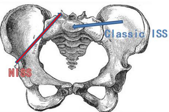
The diagrammatic sketch of two methods of ISS fixation. Blue indicates the classic ISS and red indicates the NISS
Materials and Methods
General Information
The protocol was approved by the institutional review committee (No. WXSJY-LY-2020-00216; registration date: June 5, 2020, retrospective registration), which abandoned the written consent of patients. The study cohort comprised CT scan data of 50 adults with normal pelvis from the imaging database of our hospital taken between May 2019 and April 2020. Inclusive criteria: iliosacral joint and its surrounding were healthy adult pelvis. Patients with structural abnormality of pelvic ring caused by congenital development or acquired disease or fractures of pelvis and acetabulum, lumbosacralization or lumbarization of sacrum, and 70 years old < age < 20 years old were excluded.
There were 25 males and 25 females, whose age averaged 45 years (range 20–70 years). A 64-slice CT (GE Optima CT 660) was used to scan the patients from head to foot as they lay supine. The scanning range was set from the superior margin of L3 to 5 cm below the symphysis pubis. The scanning conditions were: tube voltage 120 kV, thickness 1.0 mm, interval 1.0 mm, pitch 1.172, rotation time 0.75 s, matrix 512 × 512, FOV 350–400 mm. The raw data were reconstructed to 1.0 mm thickness, at 50% intervals and a 300 HU threshold. The CT scan images were stored in DICOM format on a CD-ROM.
Three-Dimensional Printed Pelvic Models
The pelvic scan data of 50 patients in DICOM format were transferred to a three-dimensional printer (BLANK FLAME MEDICAL, 6035H, China), and 50 pelvic models (1:1) were printed out.
Implantation of NISS
The pelvic models were placed in lateral position. A viewing device similar to that of cruciate ligament reconstruction was used. One end (A) is located at the exit point of NSIS, and the other end (B) can move on the sliding rod (C), and the exit of the positioning tube on B faces the entrance point of NSIS, i.e., the positions of the entry point and exit point of NSIS were controlled by the viewing device (Fig. 2). The entry point located at a vertical distance of 6 mm from the middle of the superior posterior quarter of the acetabular rim, and the exit point was the intersection of the vertical extension line of S1 superior articular process and the horizontal median line of S1 transverse process (Fig. 3). According to our early measurement of the anatomical parameters of NSIS, the average length of the new channel was 102 mm and the average diameter was 14.6 mm [5]. After drilling with the aid of a viewing device, screws with diameter of 6.5 mm and 7.3 mm and length of 90 mm were implanted into the left and right sides of the 50 pelvic models, respectively. Observing the screw implantation, CT scan was performed when penetrating of the channel was suspected by naked eyes.
Fig. 2.

NISS implanted with the aid of a viewing device. A Controls the exit of screw, B controls the entry point of screw, and C is the slider of the viewing device
Fig. 3.

The entry and exit points of NISS. A Is the exit point (intersection of the vertical extension line of S1 superior articular process and the horizontal median line of S1 transverse process). B (Red star) is the entry point, which is located at a vertical distance of 6 mm from the middle of the superior–posterior quarter (yellow dotted line) of the acetabular rim
Results
All the screws implanted were located within the channel, i.e. none of the implanted screws perforated the channel (Fig. 4), but 6.0% (3 models) of the screws were too long and a little bit penetrated (< 4 mm) behind the back of the channel, which was found in models with small skeletons (Fig. 5).
Fig. 4.

CT scan showed that NISS located within the channel
Fig. 5.

NISS implanted into the pelvic model. The implanted screw did not perforate the channel, but was too long and a little bit penetrated behind the back of the channel (red arrow)
Discussion
Status of Classic ISS Fixation
Iliosacral joint is a sloping plane. The exit point position cannot be accurately determined by a single AP or lateral view, so multiple and repeated intraoperative fluoroscopic images including standard inlet, outlet and lateral views are necessary. Furthermore, good-quality fluoroscopic views are necessary because the presence of contrast, intestinal gas, and increased soft tissue density from obesity can cause difficulty in obtaining and interpreting appropriate intraoperative fluoroscopic images [6–8, 13–15]. However, great differences in incidence of screw malposition (2–68%) and nerve injuries (0.5–7.9%) were reported [6–10], which indicates that the existing ISS implantation technology has a learning curve and is related to the operator's experience with certain degree of possibility of complications.
NISS Fixation
The minimum transverse diameter of NISS channel was (14.56 ± 1.51) mm, ranging from 12.20 to 18.13 mm, and the minimum longitudinal diameter was (15.22 ± 1.57) mm, ranging from 13.01 to 18.40 mm [5]. Therefore, a φ 6.5 to 7.3 mm screw is recommended.
The length of NISS channel averaged (102.35 ± 7.45) mm, ranging from 87 to 120 mm [5]. If the entry point and entry direction deviates inward and superiorly, the channel will be longer; if the entry point and entry direction deviates laterally and inferiorly, the channel will be shorter. In this study, 6% of the screws with a length of 90 mm were too long and a little bit penetrated behind the back of the channel, which was found in models with small skeletons. Therefore, in patients with small skeletons or the entry point deviates laterally and inferiorly, the length of screw should be less than 90 mm.
The entry point is close to the posterior superior edge of the acetabulum, which is a safe place. The exit point is located between the L5 and S1 nerve roots, similar to the insertion point of Roy-Camille’s pedicle screw, which has been proved to be a safe position in pedicle screw fixation. During the procedure of screw implantation, the iliac cortical density and sacral alar slope can be regarded as the superior boundary of the channel on the lateral view, and the arc top of the pelvic arc line regarded as the inner boundary of the channel on the anteroposterior view. Because the screw can be implanted with the aid of a viewing device, the entry and the exit points can be well controlled, so injuries of nerves, iliac vessels, and viscera could be avoided.
The NISS channel is longer, most of which is cortical bone, so the anti-pullout force of the screw is stronger than that of the classic ISS fixation, so NISS could be indicated for patients with severe osteoporosis; patients with posterolateral iliac fractures are also suitable for NISS because the screw does not pass through the posterolateral ilium. Therefore, NISS fixation might be used as an alternative to the classic ISS in special cases.
Due to significant differences in the measurements between males and females, which reflects the differences of gender in skeleton size and shape. Therefore, three-dimensional CT reconstruction of pelvis and simulated screw implantation should be performed before operation to realize individualized screw implantation with appropriate diameter and length.
Conclusion
The NISS implantation is simple, safe and accurate, but individualized screw implantation with appropriate diameter and length should be more accurate.
The Limitations of NISS Fixation and the Study
Only one screw with a diameter of φ 7.3 mm can be used, whereas in classic ISS fixation, two screws with φ 6.0–7.0 mm can be placed [4, 6]; patients with poor reduction in sacroiliac joint dislocation and pelvic deformity are not suitable for NSIS fixation. This study is only to investigate the effect of NISS implantation in three-dimensional printing pelvic model. Before clinical application, biomechanical stability test and implantation of NISS in cadavers are necessary.
Abbreviations
- ISS
Iliosacral screw
- NISS
New iliosacral screw
Funding
None.
Availability of data and material
Not applicable.
Code availability
None.
Declarations
Conflict of interest
The authors have no conflicts of interest relevant to this article.
Ethical Approval
The Review Board approval was obtained for this retrospective study.
Trial registration number
WXSJY-LY-2020–00216, date of registration: June 5, 2020, retrospectively registered.
Consent to participate
The Review Board approved waiving of obtaining informed consent from individual patients for this retrospective study.
Consent for publication
Consent for the publication of images obtained from the patients.
Footnotes
Publisher's Note
Springer Nature remains neutral with regard to jurisdictional claims in published maps and institutional affiliations.
Yunhong Ma and Jian Wang contributed equally.
Contributor Information
Qudong Yin, Email: Yinqudong@sina.com.
Yu Liu, Email: liuyu_md@163.com.
Dong Li, Email: Lidongyqd@163.com.
References
- 1.Pan ZJ, Hong HX, Huang ZJ, Chen X, Zheng Q, Chen WZ. Applied anatomic study of the parameters of screw fixation for the sacroiliac joint. Chinese Journal of Clinical Anatomy. 2004;22(2):125–128. [Google Scholar]
- 2.Zhang R, Yin Y, Li S, Hou Z, Jin L, Zhang Y. Percutaneous sacroiliac screw versus anterior plating for sacroiliac joint disruption: A retrospective cohort study. International Journal of Surgery. 2018;50:11–16. doi: 10.1016/j.ijsu.2017.12.017. [DOI] [PubMed] [Google Scholar]
- 3.Iorio JA, Jakoi AM, Rehman S. Percutaneous sacroiliac screw fixation of the posterior pelvic ring. Orthopedic Clinics of North America. 2015;46(4):511–521. doi: 10.1016/j.ocl.2015.06.005. [DOI] [PubMed] [Google Scholar]
- 4.Krappinger D, Lindtner RA, Benedikt S. Preoperative planning and safe intraoperative placement of iliosacral screws under fluoroscopic control. Operative Orthopädie und Traumatologie. 2019;31(6):465–473. doi: 10.1007/s00064-019-0612-x. [DOI] [PMC free article] [PubMed] [Google Scholar]
- 5.Li Dong, Ma Yunhong, Zhou Jinhua, et al. Applied anatomical parameters measurement of sacroiliac screw passing the back of sacrum by CT digital reconstructed technology. Chinese Journal of Clinical Anatomy, 2021;39(5): (in press)
- 6.M, Braun C, Flatz W, Böcker W, Kammerlander C. Biomechanical stability of sacroiliac screw osteosynthesis with and without cement augmentation. Injury. 2020; S0020–1383(20)30071–1. [DOI] [PubMed]
- 7.Gras F, Marintschev I, Wilharm A, Klos K, Mückley T, Hofmann GO. 2D-fluoroscopic navigated percutaneous screw fixation of pelvic ring injuries—a case series. BMC Musculoskeletal Disorders. 2010;11:153. doi: 10.1186/1471-2474-11-153. [DOI] [PMC free article] [PubMed] [Google Scholar]
- 8.Wei W, Wang H, Xia ZY, Wang L. The measurement of the screwing trajectory's parameters of the sacroiliac screw for iliosacral joint disruption by the computed tomography. Journal of Hebei Medical University. 2018;39(3):293–296. [Google Scholar]
- 9.Axel G, Tobias H, Krettek C. Percutaneous iliosacral screw fixation of unstable pelvic injuries by conventional fluoroscopy. Operative Orthopdie and Traumatologie. 2006;18(3):225. doi: 10.1007/s00064-006-1173-3. [DOI] [PubMed] [Google Scholar]
- 10.Khaled SA, Soliman OW. Functional outcome of unstable pelvic ring injuries after iliosacral screw fixation: Single versus two screw fixation. European Journal of Trauma & Emergency Surgery. 2015;41(4):387–392. doi: 10.1007/s00068-014-0456-x. [DOI] [PubMed] [Google Scholar]
- 11.Collinge CA, Crist BD. Combined percutaneous iliosacral screw fixation with sacroplasty using resorbable calcium phosphate cement for osteoporotic pelvic fractures requiring surgery. Journal of Orthopaedic Trauma. 2016;30(6):e217–e222. doi: 10.1097/BOT.0000000000000520. [DOI] [PubMed] [Google Scholar]
- 12.Osterhoff G, Dodd AE, Unno F, Wong A, Amiri S, Lefaivre KA, Guy P. Cement augmentation in sacroiliac screw fixation offers modest biomechanical advantages in a cadaver model. Clinical Orthopaedics and Related Research. 2016;474(11):2522–2530. doi: 10.1007/s11999-016-4934-9. [DOI] [PMC free article] [PubMed] [Google Scholar]
- 13.Grossterlinden L, Rueger J, Catala-Lehnen P, Rupprecht M, Lehmann W, Rücker A, Briem D. Factors influencing the accuracy of iliosacral screw placement in trauma patients. International Orthopaedics. 2011;35(9):1391–1396. doi: 10.1007/s00264-010-1092-7. [DOI] [PMC free article] [PubMed] [Google Scholar]
- 14.Tidwell J, Cho R, Reid JS, Boateng H, Copeland C, Sirlin E. Percutaneous sacroiliac screw technique. Journal of Orthopaedic Trauma. 2016;30(Suppl 2):19–20. doi: 10.1097/BOT.0000000000000606. [DOI] [PubMed] [Google Scholar]
- 15.Elzohairy MM, Salama AM. Open reduction internal fixation versus percutaneous iliosacral screw fixation for unstable posterior pelvic ring disruptions. Orthopaedics & Traumatology, Surgery & Research. 2017;103:223–227. doi: 10.1016/j.otsr.2016.12.002. [DOI] [PubMed] [Google Scholar]
Associated Data
This section collects any data citations, data availability statements, or supplementary materials included in this article.
Data Availability Statement
Not applicable.
None.