Abstract
Objective:
To investigate whether resonance frequency analysis (RFA) is suitable to measure orthodontic mini-implant stability. Implant size significantly affects the level of resonance frequency. Regarding the operating mode of RFA, it has to be proven whether the resonance frequency of mini-implants in bone fits the range of frequency emitted by the Osstell ISQ device.
Material and Methods:
For this purpose the SmartPegs in the Osstell ISQ device were modified to fit with the inner screw thread of orthodontic mini-implants, and 110 mini-implants were inserted into porcine pelvic bone. RFA was performed parallel and perpendicular to the run of superficial bone fibers. A suitability test, Periotest, was also performed in the same directions. Compacta thickness was measured using cone-beam computed tomography. Correlation tests and linear regression analysis were carried out between the three methods.
Results:
The RFA showed a mean Implant Stability Quotient value of 36.36 ± 2.67, and the Periotest mean value was −2.10 ± 1.17. The differences between the two directions of measurement were statistically significant (P > .001) for RFA and the Periotest. There was a high correlation between RFA and the Periotest (r = −0.90) and between RFA and compacta thickness (r = 0.71). The comparison between the Periotest and compacta thickness showed a correlation coefficient of r = −0.64.
Conclusion:
The present results suggest that RFA is feasible as a measurement method for orthodontic mini-implant stability. As a consequence, it could be used for clinical evaluation of current stability and allow stability-related loading of mini-implants to reduce the failure rate.
Keywords: Orthodontics, Skeletal anchorage, Implant stability, Resonance frequency analysis
INTRODUCTION
Anchorage stability is a basic success factor in orthodontic treatment. That is why skeletal anchorage is established, especially in complex cases. Beside surgical plates1 and implants,2 orthodontic mini-implants have become very popular lately. Reasons might be because they are less invasive and cost less.3–7 Because of their versatility they have made new kinds of mechanics and treatment options possible.8,9
However, one disadvantage of these anchorage devices is a failure rate that is still too high. Two systematic reviews in the literature report mean overall failure rates of 16.4%.10,11
Different suggestions have been made to increase survival rates. The basic requirement is sufficient primary stability.12 To ensure this, different aspects of implant design13–16 and insertion protocol17–20 should be considered.
Determining primary stability after insertion can help predict success. In this regard, the measurement of insertion torque is the most commonly used method today.12 During the healing phase or loading the stability of a mini-implant is subject to changes because of the remodeling processes.21 To realize an optimal loading protocol it would be helpful to be able to assess the stability in every phase of treatment. Some methods have been described in publications dealing with dental implants.
The Periotest device (Medzintechnik Gulden e K, Modautal, Germany) was designed to measure the damping characteristics of the periodontium of teeth.22 A small pistil is accelerated toward the tooth, which is deflected depending on its periodontal situation. A piezoelectric crystal integrated in the head of the pistil is deformed by the contact with the tooth and generates an electric impulse. The contact time is calculated into Periotest values ranging from −8 to +50. Brägger et al.23 first used it to determine implant stability.
An alternative method for measuring implant stability is resonance frequency analysis (RFA).24 In the Osstell ISQ RFA device (Osstell, Gothenburg, Sweden), a top piece containing a magnet, called a “SmartPeg,” is screwed to the implant's head. A handpiece emits electromagnetic impulses from 5 to 15 kHz toward the SmartPeg and detects the resonance frequency of the SmartPeg implant unit. The unit of measurement is the Implant Stability Quotient (ISQ), which ranges from 0 to 100. The results of RFA depend on implant size and design.25 Because of the significant differences in length and diameter between dental implants and orthodontic mini-implants it still has to be investigated whether the range of frequency emitted by the Osstell ISQ device is suitable for an orthodontic mini-implant. If so, it could be used routinely to monitor mini-implant stability during treatment.
This study compares the ISQ values of RFA with Periotest measurements and the diameter of compact bone in contact to the implant using cone-beam computed tomography (CBCT) of orthodontic mini-implants in vitro.
MATERIALS AND METHODS
Porcine pelvic bone was cut into pieces of 3 × 4 cm. These samples were embedded into acrylic blocks (Palapress, Hereaus Kulzer; Hanau, Germany). After a curing process, a quadratic grid for mini-implant insertion was drawn with distances of 6 mm between the marker points.
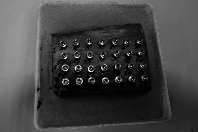
Predrilling was performed with a diameter of 1.5 mm to a depth of 4 mm using a box column drill. Benefit mini-implants (PSM medical solutions; Tuttlingen, Germany) of a size of 2 × 9 mm were used is this study. These mini-implants have a special kind of head with an inner screw thread. Different kinds of abutments can be screwed onto the head, creating a stable connection between the implant and the mechanics (Figure 1). The mini-implants were inserted rectangularly to the bone surface using an Elcomed surgical machine (W and H, Salzburg, Austria) until a distance of 1.5 mm between bone surface and implant shoulder was reached. Overall, 110 mini-implants were distributed over five bone blocks (Figure 2).
Figure 1. .
Benefit-System (PSM medical solutions; Tuttlingen, Germany) with different abutments. (A) Mini-implant. (B) Laboratory analog. (C) Impression cap. (D) Wire abutment with wire in place. (E) Bracket abutment. (F) Standard abutment. (G) Slot abutment. (H) Screwdriver for abutment fixation.
Figure 2. .
Embedded porcine pelvic bone with mini-implants.
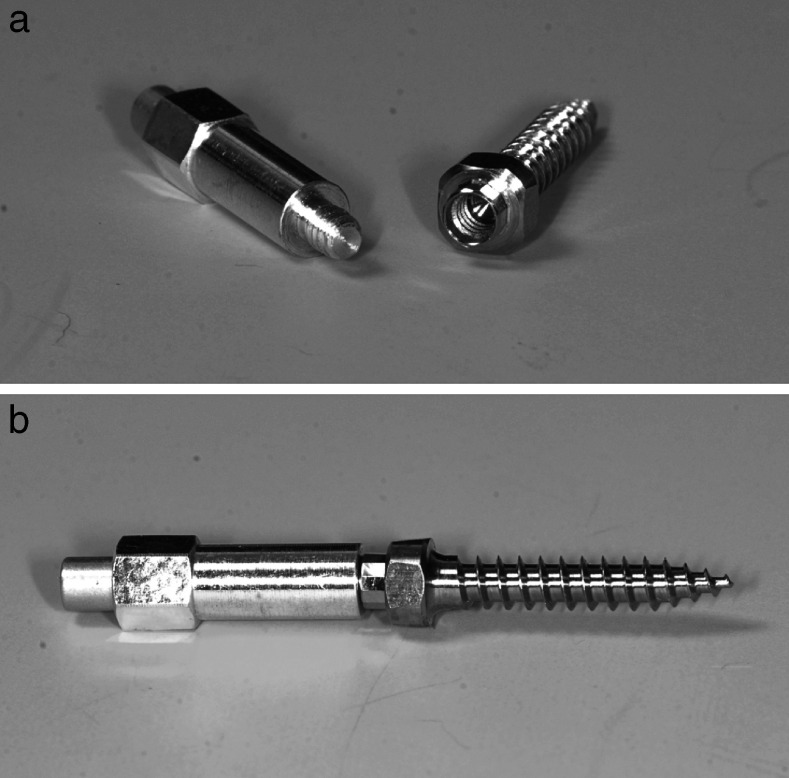
For RFA the Osstell ISQ device was used. The SmartPeg type 1 was modified in cooperation with Osstell to achieve a precise fit with the mini-implant (Figure 3a,b).
Figure 3. .
(A) Modified SmartPeg type 1 and a mini-implant with inner screw thread. (B) Stable coupling between SmartPeg and mini-implant for exact RFA measurement.
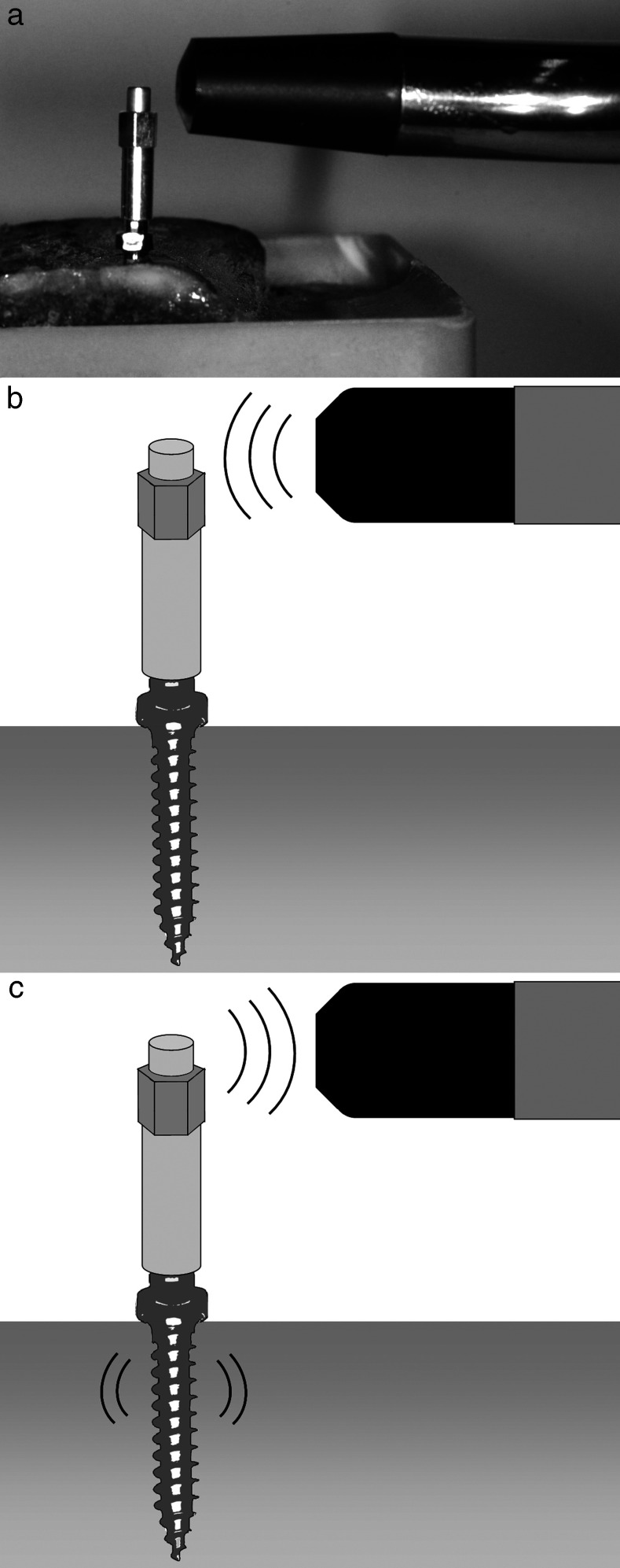
For measurements it was screwed onto the implant's head with a torque of 4–6 Ncm using a torque control ratchet drill. The measurement probe was held close to the top of the SmartPeg without touching (Figure 4).
Figure 4. .
RFA measurement of an orthodontic mini-implant using the Osstell ISQ device (a) A modified SmartPeg is screwed to the mini-implant, and the measurement probe is held close to top of the SmartPeg. (b) The measurement probe emits electromagnetic impulses toward the SmartPeg. (c) Detection of the resonance frequency of the SmartPeg implant unit.
Verification of the Implant-SmartPeg-coupling
To verify the quality of the new threads and the reproducibility of measurements, a preliminary test was performed. For this purpose a mini-implant was inserted into a bone block. Afterward a modified SmartPeg was attached and removed 100 times. Each time RFA measurement was performed three times in the same direction to the bone. The standard error of all measurements was calculated.
Main Experiment
ISQ values were measured three times parallel to the run of the superficial cortical fibers of the porcine bone and afterward three times perpendicular to it. For analysis, the arithmetic mean of the three values of each direction and the overall mean values for each mini-implant were calculated.
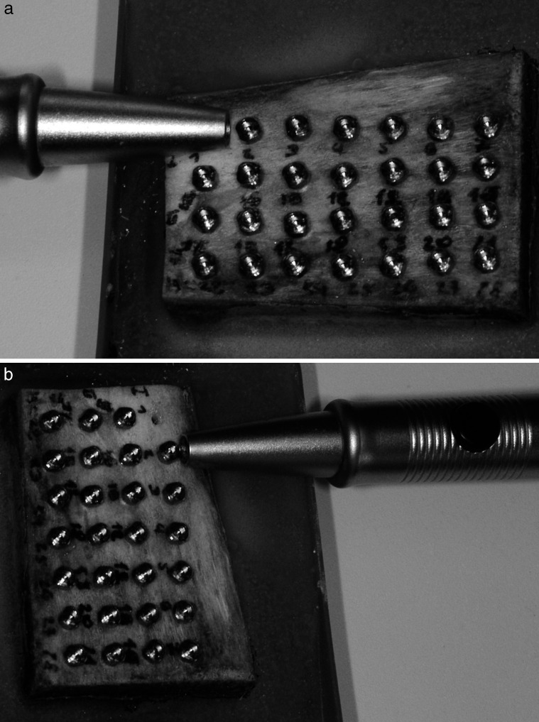
The Periotest measurements were conducted by holding the handpiece rectangularly to the axis of the mini-implant. Values were also detected three times parallel and three times perpendicular to the run of the cortical bone fibers (Figure 5a,b). Each mini-implant had to be removed after measurement to allow the correct angulation of the handpiece to the next mini-implant.
Figure 5. .
Periotest measurement of a mini-implant parallel (a) and perpendicular (b) to the run of the superficial bone fibers. For exact angulation of the handpiece rectangular to bone surface the previous mini-implant had to be removed.
To avoid metal artifacts CBCT (Pax-Duo 3D, Orangedental, Biberach, Germany) of the bone blocks was performed without mini-implants. The samples were positioned using a plastic container with a platform for reproducible positioning. The exposure settings were 90kV, 3.1 mA with a voxel size of 0.2 × 0.2 mm, a field of view of 5 cm × 5 cm × 5 cm and an acquisition time of 15 seconds. For measuring, Ez3D2009 imaging software version 1.2.1.0 (Vatech Co Ltd, Seoul, Korea) was applied using a 2.4 GHz Intel Xenon PC system (Intel, Santa Clara, Calif). The monitor was 19-in diagonal with a resolution of 1280 × 1024 pixels (HP Compaq LA 1951g, Hewlett Packard, Wilmington, Del). In combination with window shades and dimmable light, a standardized low-light ambience illumination was generated.
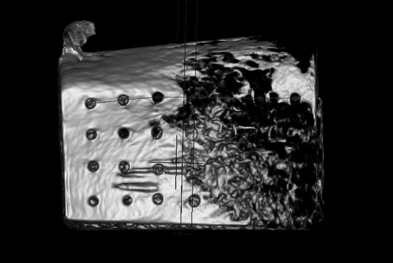
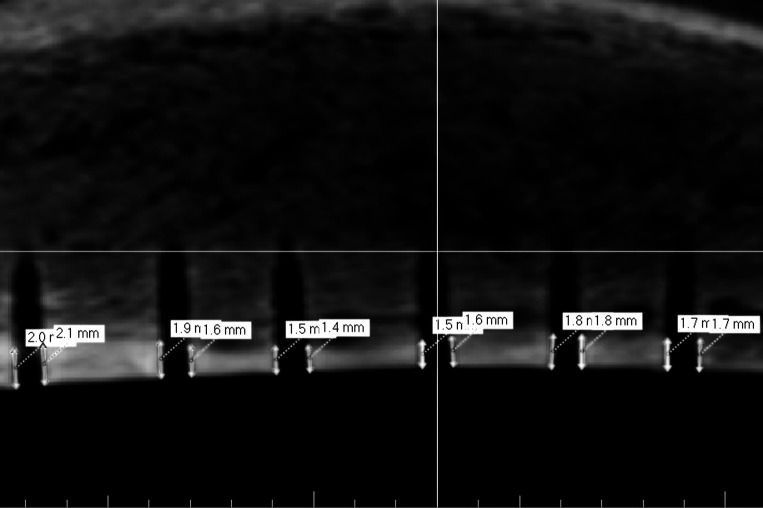
The first three-dimensional reconstructions were used to evaluate the sectional plane containing the middle of each insertion hole (Figure 6). Measurements were performed on the resulting two-dimensional projections. The compacta thickness was measured on the right and left boundaries of the insertion hole (Figure 7). Arithmetic means were calculated to get one value for each mini-implant. All values, ISQ, Periotest, and compacta thickness, were tested for normal distribution by Kolmogorov-Smirnov test.
Figure 6. .
Three-dimensional reconstruction of a bone block after mini-implant removal using CBCT for determination of the sectional plane.
Figure 7. .
Two-dimensional projection for measurement of compacta thickness.
Differences between parallel and perpendicular values within the same method were investigated using the paired t-test for Periotest and the Wilcoxon test for RFA. Coefficients of correlation between ISQ, Periotest, and compacta thickness were calculated using the Pearson correlation test. To analyze the relationship between RFA, Periotest, and compacta thickness regression analysis was carried out.
All statistical calculations were performed using SPSS (IBM, Armonk, NY) version 19.
RESULTS
The outcomes of the reproducibility test of the coupling were very uniform. The mean ISQ value was 40.9 ± 0.31 with a standard error of 0.031.
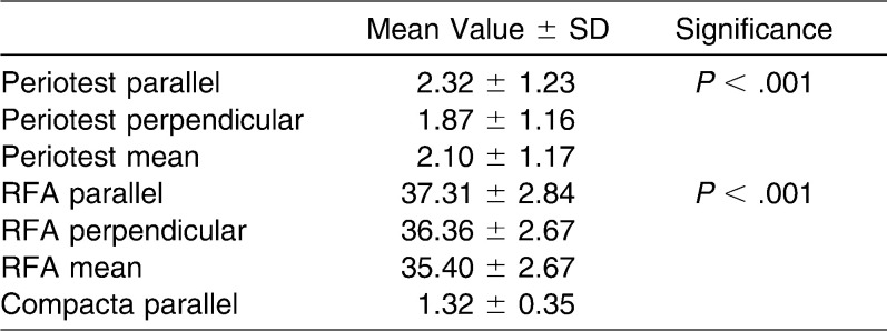
RFA showed mean ISQ values of 35.40 ± 2.67 perpendicular to bone fibers and 37.31 ± 2.84 parallel to it, with overall mean value of 36.36 ± 2.67 (Figure 8a). The Kolmogorov-Smirnov test rejected normal distribution for perpendicular, parallel, and mean results (P > .001). As a consequence, a Wilcoxon test was performed, which showed significant differences between perpendicular and parallel values (P > .001) (Table 1).
Figure 8. .
Parallel and perpendicular measurements and mean values for (a) RFA and (b) Periotest.
Table 1. .
RFA, Periotest, and Compacta Thickness Measurements
Periotest measurements showed mean values of −1.87 ± 1.16 perpendicular to bone fibers and −2.32 ± 1.23 parallel to it. The overall mean value was −2.10 ± 1.17 (Figure 8b). The results showed normal distribution for parallel, perpendicular, and mean values, with P = .2 using the Kolmogorov-Smirnov test. A paired t-test between parallel and perpendicular values revealed significant differences (P > .001).
The investigation of compact bone thicknesses resulted in mean values of 1.32 ± 0.35 mm with a normal distribution (P = .2).
Correlation tests and linear regression analysis between the three methods for stability measurement were performed (Table 2). For a correlation coefficient |r| ≥ 0.7, a correlation was suggested. Pearson correlation test between Periotest and RFA showed correlation coefficients of r = −0.869 for perpendicular, r = −0.87 for parallel, and r = −0.90 for mean overall values with a significance of P > .001, which means a high strength of correlation between the two methods (Figure 9).
Figure 9. .

Correlation between RFA mean values and Periotest mean values, including regression line.
Table 2. .
Pearson Correlation Test and Linear Regression Analysis
A correlation could also be found between RFA and compact bone thickness with a correlation coefficient of r = 0.71 (P > .001) (Figure 10).
Figure 10. .

Correlation between RFA parallel values and compacta thickness, including regression line.
The comparison between parallel Periotest values and compacta thickness resulted in a correlation coefficient of r = −0.64 (P > .001) and thus just missed the limit of 0.7 (Figure 11).
Figure 11. .
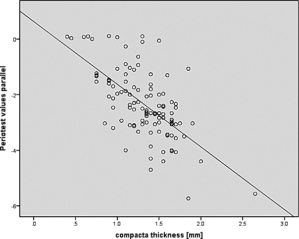
Correlation between Periotest parallel values and compacta thickness, including regression line.
DISCUSSION
RFA is regarded as the gold standard for clinical stability measurement of dental implants.26 Therefore, it would be desirable to use it to evaluate orthodontic mini-implants as well. One problem is the connection between the mini-implant and the SmartPeg. Because of the sensitivity of this measurement technique, a stable and reproducible connection must be ensured to make it work. Most dental implant systems have an inner screw thread so the RFA system is based on a screw coupling. The first pilot studies regarding RFA for mini-implants used adhesive fixation of a magnet to the mini-implant's head.27 The results suggested that RFA might work for mini-implants. Going for exact quantitative measurement this might be insufficiently reproducible or stable. Another study modifies the head of mini-implants into an external screw head. This can be useful for stability measurement in animal studies if it is made accurately, but for clinical use this would prevent attaching any kind of mechanics for tooth movement.28 The mini-implants used in this study have an industrially fabricated inner thread at the top. It is made for fixation of prefabricated abutments to create different kind of mechanics. In cooperation with Osstell, the SmartPeg type 1 was modified by the precision engineering facility of the university, and the quality of the threads was controlled under microscope. Stability and reproducibility were verified by the preliminary test.
The next problem with using RFA for mini-implants is the reduced size compared with dental implants. Implant size significantly affects the level of resonance frequency. Regarding the operating mode of RFA, it has to be proven whether the resonance frequency of mini-implants in bone fits the range of frequency emitted by the Osstell ISQ. Otherwise the results would not be sensitive or significant. So the validation of RFA for mini-implants should be performed before using it as measuring method in further studies or clinical routine. One possibility can be the comparison of RFA to other methods for stability measurement, such as Periotest or surrounding bone. The operation mode of this method is less complex and obviously precisely working, independent from implant size.
Periotest has a high prognostic capacity regarding early implant failure.29 Especially in vitro, the results are significant because a perfect angulation of the handpiece, which is essential for accurate measurement, can be ensured. There is a high correlation between RFA and Periotest for dental implants.30 Under standardized conditions in acrylic blocks with simulated bone loss a correlation was also found between the two methods with a higher precision of the RFA.26 This affirms the high potential of RFA. The present results also show a high correlation between the two methods.
There are many studies confirming the importance of the contact between implant and surrounding bone.31–35 In particular, the contact with the compact bone seems to be important for implant stability.36 A correlation could found between the bone to implant contact rate and RFA.37 The present study compares the thickness of compact bone in contact to the mini-implant using CBCT with RFA and Periotest. The software and hardware used for investigations are technically approved for radiological observations. Measurements were performed under standardized low-light conditions. The results showed a significant correlation between RFA and bone thickness, whereas the comparison between bone thickness and Periotest only showed a correlation coefficient of r = −0.64. The results confirm the adaptability of this protocol of RFA for mini-implants. Nevertheless, a histomorphometric analysis including the spongiosa could give more precise results.
In this study Periotest and RFA were investigated parallel and perpendicular to the bone fibers of the pig bone. There were significant differences between the direction of measurements both for Periotest and RFA. In a previous study,38 ISQ values were not affected by the direction of the probe in a pig bone model. These differences might be based on the sensitiveness of the RFA design used in this study.
CONCLUSIONS
The present results suggest that RFA can be used as measurement method for mini-implant stability.
In the future RFA might be used routinely to assess mini-implant stability throughout the course of treatment.
As a consequence, clinical evaluation of current stability will allow stability related loading of mini-implants and thus might reduce the failure rate of orthodontic mini-implants.
REFERENCES
- 1.Umemori M, Sugawara J, Mitani H, Nagasaka H, Kawamura H. Skeletal anchorage system for open-bite correction. Am J Orthod Dentofacial Orthop. 1999;115:166–174. doi: 10.1016/S0889-5406(99)70345-8. [DOI] [PubMed] [Google Scholar]
- 2.Wehrbein H, Glatzmaier J, Mundwiller U, Diedrich P. The Orthosystem—a new implant system for orthodontic anchorage in the palate. J Orofac Orthop. 1996;57:142–153. doi: 10.1007/BF02191878. [DOI] [PubMed] [Google Scholar]
- 3.Costa A, Raffainl M, Melsen B. Miniscrews as orthodontic anchorage: a preliminary report. Int J Adult Orthodon Orthognath Surg. 1998;13:201–209. [PubMed] [Google Scholar]
- 4.Melsen B, Costa A. Immediate loading of implants used for orthodontic anchorage. Clin Orthod Res. 2000;3:23–28. doi: 10.1034/j.1600-0544.2000.030105.x. [DOI] [PubMed] [Google Scholar]
- 5.Wilmes B, editor. Fields of Application of Miniimplants. London, UK: Quintessence; 2008. [Google Scholar]
- 6.Berens A, Wiechmann D, Dempf R. Mini- and micro-screws for temporary skeletal anchorage in orthodontic therapy. J Orofac Orthop. 2006;67:450–458. doi: 10.1007/s00056-006-0601-1. [DOI] [PubMed] [Google Scholar]
- 7.Kanomi R. Mini-implant for orthodontic anchorage. J Clin Orthod. 1997;31:763–767. [PubMed] [Google Scholar]
- 8.Wilmes B, Drescher D. Vertical periodontal ligament distraction—a new method for aligning ankylosed and displaced canines. J Orofac Orthop. 2009;70:213–223. doi: 10.1007/s00056-009-8811-y. [DOI] [PubMed] [Google Scholar]
- 9.Wilmes B, Nienkemper M, Drescher D. Application and effectiveness of a mini-implant- and tooth-borne rapid palatal expansion device: the hybrid hyrax. World J Orthod. 2010;11:323–330. [PubMed] [Google Scholar]
- 10.Schatzle M, Mannchen R, Zwahlen M, Lang NP. Survival and failure rates of orthodontic temporary anchorage devices: a systematic review. Clin Oral Implants Res. 2009;20:1351–1359. doi: 10.1111/j.1600-0501.2009.01754.x. [DOI] [PubMed] [Google Scholar]
- 11.Stanford N. Mini-screws success rates sufficient for orthodontic treatment. Evid Based Dent. 2011;12:19. doi: 10.1038/sj.ebd.6400777. [DOI] [PubMed] [Google Scholar]
- 12.Su YY. Primary Stability of Orthodontic MiniImplants Analysis of Biomechanical Properties and Clinical Relevance. Düsseldorf, Germany: Heinrich-Heine-Universität; 2009. [Google Scholar]
- 13.Miyawaki S, Koyama I, Inoue M, Mishima K, Sugahara T, Takano-Yamamoto T. Factors associated with the stability of titanium screws placed in the posterior region for orthodontic anchorage. Am J Orthod Dentofacial Orthop. 2003;124:373–378. doi: 10.1016/s0889-5406(03)00565-1. [DOI] [PubMed] [Google Scholar]
- 14.Wiechmann D, Meyer U, Buchter A. Success rate of mini- and micro-implants used for orthodontic anchorage: a prospective clinical study. Clin Oral Implants Res. 2007;18:263–267. doi: 10.1111/j.1600-0501.2006.01325.x. [DOI] [PubMed] [Google Scholar]
- 15.Chen CH, Chang CS, Hsieh CH, et al. The use of microimplants in orthodontic anchorage. J Oral Maxillofac Surg. 2006;64:1209–1213. doi: 10.1016/j.joms.2006.04.016. [DOI] [PubMed] [Google Scholar]
- 16.Wilmes B, Rademacher C, Olthoff G, Drescher D. Parameters affecting primary stability of orthodontic mini-implants. J Orofac Orthop. 2006;67:162–174. doi: 10.1007/s00056-006-0611-z. [DOI] [PubMed] [Google Scholar]
- 17.Wilmes B, Drescher D. Impact of insertion depth and predrilling diameter on primary stability of orthodontic mini-implants. Angle Orthod. 2009;79:609–614. doi: 10.2319/071708-373.1. [DOI] [PubMed] [Google Scholar]
- 18.Kang S, Lee SJ, Ahn SJ, Heo MS, Kim TW. Bone thickness of the palate for orthodontic mini-implant anchorage in adults. Am J Orthod Dentofacial Orthop. 2007;131:S74–S81. doi: 10.1016/j.ajodo.2005.09.029. [DOI] [PubMed] [Google Scholar]
- 19.Kim HJ, Yun HS, Park HD, Kim DH, Park YC. Soft-tissue and cortical-bone thickness at orthodontic implant sites. Am J Orthod Dentofacial Orthop. 2006;130:177–182. doi: 10.1016/j.ajodo.2004.12.024. [DOI] [PubMed] [Google Scholar]
- 20.Kuroda S, Yamada K, Deguchi T, Hashimoto T, Kyung HM, Takano-Yamamoto T. Root proximity is a major factor for screw failure in orthodontic anchorage. Am J Orthod Dentofacial Orthop. 2007;131:S68–S73. doi: 10.1016/j.ajodo.2006.06.017. [DOI] [PubMed] [Google Scholar]
- 21.Gedrange T, Proff P, Bayerlein T, Landsberger P, Dietze S, Fanghanel J. Histological and fluorescence microscopic examination of the bone/implant interface in orthodontic miniscrews (Mondeal) Folia Morphol (Warsz) 2006;65:70–71. [PubMed] [Google Scholar]
- 22.Lukas D, Schulte W. Periotest—a dynamic procedure for the diagnosis of the human periodontium. Clin Phys Physiol Meas. 1990;11:65–75. doi: 10.1088/0143-0815/11/1/006. [DOI] [PubMed] [Google Scholar]
- 23.Brägger U, Hugel-Pisoni C, Burgin W, Buser D, Lang NP. Correlations between radiographic, clinical and mobility parameters after loading of oral implants with fixed partial dentures. A 2-year longitudinal study. Clin Oral Implants Res. 1996;7:230–239. doi: 10.1034/j.1600-0501.1996.070305.x. [DOI] [PubMed] [Google Scholar]
- 24.Meredith N, Alleyne D, Cawley P. Quantitative determination of the stability of the implant-tissue interface using resonance frequency analysis. Clin Oral Implants Res. 1996;7:261–267. doi: 10.1034/j.1600-0501.1996.070308.x. [DOI] [PubMed] [Google Scholar]
- 25.Kang IH, Kim CW, Lim YJ, Kim MJ. A comparative study on the initial stability of different implants placed above the bone level using resonance frequency analysis. J Adv Prosthodont. 2011;3:190–195. doi: 10.4047/jap.2011.3.4.190. [DOI] [PMC free article] [PubMed] [Google Scholar]
- 26.Lachmann S, Laval JY, Jager B, et al. Resonance frequency analysis and damping capacity assessment. Part 2: peri-implant bone loss follow-up. An in vitro study with the Periotest and Osstell instruments. Clin Oral Implants Res. 2006;17:80–84. doi: 10.1111/j.1600-0501.2005.01174.x. [DOI] [PubMed] [Google Scholar]
- 27.Su YY, Wilmes B, Honscheid R, Drescher D. Application of a wireless resonance frequency transducer to assess primary stability of orthodontic mini-implants: an in vitro study in pig ilia. Int J Oral Maxillofac Implants. 2009;24:647–654. [PubMed] [Google Scholar]
- 28.Uysal T, Ekizer A, Akcay H, Etoz O, Guray E. Resonance frequency analysis of orthodontic miniscrews subjected to light-emitting diode photobiomodulation therapy. Eur J Orthod. 2010;34:44–51. doi: 10.1093/ejo/cjq166. [DOI] [PubMed] [Google Scholar]
- 29.Noguerol B, Munoz R, Mesa F, de Dios Luna J, O'Valle F. Early implant failure. Prognostic capacity of Periotest: retrospective study of a large sample. Clin Oral Implants Res. 2006;17:459–464. doi: 10.1111/j.1600-0501.2006.01250.x. [DOI] [PubMed] [Google Scholar]
- 30.Lachmann S, Jager B, Axmann D, Gomez-Roman G, Groten M, Weber H. Resonance frequency analysis and damping capacity assessment. Part I: an in vitro study on measurement reliability and a method of comparison in the determination of primary dental implant stability. Clin Oral Implants Res. 2006;17:75–79. doi: 10.1111/j.1600-0501.2005.01173.x. [DOI] [PubMed] [Google Scholar]
- 31.Buchter A, Kleinheinz J, Wiesmann HP, et al. Biological and biomechanical evaluation of bone remodelling and implant stability after using an osteotome technique. Clin Oral Implants Res. 2005;16:1–8. doi: 10.1111/j.1600-0501.2004.01081.x. [DOI] [PubMed] [Google Scholar]
- 32.Schwarz F, Sager M, Kadelka I, Ferrari D, Becker J. Influence of titanium implant surface characteristics on bone regeneration in dehiscence-type defects: an experimental study in dogs. J Clin Periodontol. 2010;37:466–473. doi: 10.1111/j.1600-051X.2010.01533.x. [DOI] [PubMed] [Google Scholar]
- 33.Schwarz F, Sahm N, Iglhaut G, Becker J. Impact of the method of surface debridement and decontamination on the clinical outcome following combined surgical therapy of peri-implantitis: a randomized controlled clinical study. J Clin Periodontol. 2011;38:276–284. doi: 10.1111/j.1600-051X.2010.01690.x. [DOI] [PubMed] [Google Scholar]
- 34.Buchter A, Kleinheinz J, Wiesmann HP, Jayaranan M, Joos U, Meyer U. Interface reaction at dental implants inserted in condensed bone. Clin Oral Implants Res. 2005;16:509–517. doi: 10.1111/j.1600-0501.2005.01111.x. [DOI] [PubMed] [Google Scholar]
- 35.Buchter A, Wiechmann D, Gaertner C, et al. Load-related bone modelling at the interface of orthodontic micro-implants. Clin Oral Implants Res. 2006;17:714–722. doi: 10.1111/j.1600-0501.2006.01233.x. [DOI] [PubMed] [Google Scholar]
- 36.Buchter A, Kleinheinz J, Wiesmann HP, Seper L, Joos U, Meyer U. Peri-implant bone formation around cylindrical and conical implant systems [in German] Mund Kiefer Gesichtschir. 2004;8:282–288. doi: 10.1007/s10006-004-0557-5. [DOI] [PubMed] [Google Scholar]
- 37.Scarano A, Degidi M, Iezzi G, Petrone G, Piattelli A. Correlation between implant stability quotient and bone-implant contact: a retrospective histological and histomorphometrical study of seven titanium implants retrieved from humans. Clin Implant Dent Relat Res. 2006;8:218–222. doi: 10.1111/j.1708-8208.2006.00022.x. [DOI] [PubMed] [Google Scholar]
- 38.Ohta K, Takechi M, Minami M, et al. Influence of factors related to implant stability detected by wireless resonance frequency analysis device. J Oral Rehabil. 2010;37:131–137. doi: 10.1111/j.1365-2842.2009.02032.x. [DOI] [PubMed] [Google Scholar]


