Abstract
Introduction/Background:
To describe the clinical implementation and optimization of magnetic resonance imaging (MRI) systems installed in a radiation oncology department for dedicated use in radiotherapy (RT) simulation and treatment planning for pediatric patients.
Methods:
Two wide-bore MRI systems were installed and commissioned in 2016. Patient setups, coil placements, and scan protocols were developed to image various anatomic sites in children. Patients with brain tumors were routinely imaged using a pair of flexible loop coils and a posterior receiver coil integrated into the patient couch. The integrated posterior coil and the flexible anterior torso coil supported by the coil bridge were used together when imaging the abdomen, pelvis, or spine. Three-dimensional acquisition was most often performed, given the benefit of high-resolution multiplanar reformation as well as elimination of B0 related distortions in the slice selection direction.
Results:
We performed 542 MRI studies (265 for planning and 277 for monitoring on-treatment tumor changes) on pediatric patients in the first year after system installation. Multi-sequence images of pediatric RT patients with ependymoma, medulloblastoma, craniopharyngioma, rhabdomyosarcoma, or Ewing sarcoma were shown to illustrate the image quality obtainable with optimized planning sequences.
Conclusions:
MRI of pediatric patients in their treatment positions with setup devices in place can be performed with coil arrangements that include flexible coils. The resulting image quality is suitable for treatment planning and on-treatment monitoring. We provide optimized site-specific sequence parameters to support the continued improvement of MRI for pediatric RT planning.
INTRODUCTION
Magnetic resonance imaging (MRI) is increasingly used in radiotherapy (RT) clinics for treatment planning and MR-guided RT. Numerous publications demonstrating the potential benefits of MRI for adaptive therapy for soft-tissue tumors, the feasibility of MR-only simulation, and the utility of 4D MRI for tumor-motion management have generated increased interest in this approach.1–3 MRI offers the ability to differentiate between tumor components, e.g., solid and cystic components, necrosis, hemorrhage, restricted diffusion, or peritumoral edema, which is not easily achievable with computed tomography (CT).
Performing MRI on pediatric patients for diagnosis and treatment planning presents several challenges.4–6 Children fatigued after a CT simulation may have difficulty remaining motionless during the subsequent MR simulation, and extra effort and personnel are often required to reduce their anxiety before they undergo MRI. Safety precautions are needed when operating MR-conditional anesthesia equipment inside the magnet room. The amount of energy deposited in the patient’s body tissues, also known as the specific absorption rate, must be carefully monitored when adjusting the parameters of radiofrequency (RF)-intense sequences at higher field strengths. Most pediatric coils were designed for diagnostic MRI and cannot be used for imaging patients in treatment positions. As no pre-optimized, site-specific sequence libraries for pediatric RT treatment planning are available from vendors or clinical trial cooperative groups, radiation oncology departments must spend considerable time and effort in developing their own.
The Panorama 0.23T R/T scanner (Philips Healthcare, Best, The Netherlands)7,8 was the first commercial MRI system dedicated for radiation oncology use. Our department installed one of these simulators in 2004. When vendors offered packages that enabled diagnostic MRI systems to accommodate the setup required for RT patients, we replaced our low-field system with a 1.5T superconducting closed-bore system. Our equipment was further upgraded in 2016 to two wide-bore MRI systems (Ingenia, Philips Healthcare) with higher field strengths (1.5T and 3T) and oncology configurations. Here, we describe the clinical implementation of these systems and efforts to optimize them for imaging pediatric patients. The image quality obtained for patients in their treatment positions with setup devices in place is demonstrated. The challenges of clinical implementation including potential issues with MR-only simulation are highlighted, and areas requiring improvement are discussed. We anticipate that our findings will benefit those interested in implementing an MRI simulator or optimizing their existing systems and pulse sequences for pediatric patients.
METHODS
System description
The 1.5T superconducting MRI system was installed near the photon therapy area in our department, and the 3T system was installed in the proton therapy center. The 1.5T system is equipped with the Omega gradient system (with peak gradient amplitude of 33 mT/m and peak slew rate of 120 mT/m/ms) with the ScanTools Plus sequence package. The 3T system is equipped with the Omega HP gradient system (with peak gradient amplitude of 45 mT/m and peak slew rate of 200 mT/m/ms) with the ScanTools Premium sequence package. A 3T dStream 32-channel head coil was purchased for increased signal-to-noise ratio (SNR) and acquisition acceleration. Both MRI systems have a 70-cm patient aperture, a 53-cm-wide indexed flat table top, and an LAP DORADOnova MR3T laser bridge (LAP of America LLC, Boynton Beach, FL) mounted in front of the magnet. To date, the 1.5T system has been used as the primary MRI system to image patients for treatment planning, because it is easier to transport patients to the 1.5T system from the adjacent CT simulator. For on-treatment imaging, the proximity of the treatment room determined which MRI system (1.5T or 3T) was used. For example, patients who received proton therapy would undergo MRI during the treatment course consistently on the 3T system in the proton therapy center, even their initial planning scan was performed on 1.5T. When comparing on-treatment images to planning images for detecting tumor volume changes, physicians considered the potential impacts of different magnet strengths, such as noise, susceptibility effect, and image artifact. Although the same MR unit for both planning and on-treatment studies is preferred for consistency, no discrepancy in tumor volume due to the difference in magnet strength has been reported to warrant a change in our practice.
Patient setup and RF coil placement for brain imaging
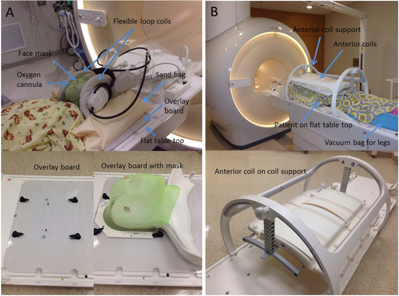
Patients underwent MRI after CT simulation for treatment planning or during the treatment course to monitor changes in the tumor shape and volume. All patients with brain tumors in the posterior fossa or with spinal canal involvement were imaged in flexible loop coils in their masks and treatment positions to maintain the flexion of brainstem and cervical spine (Fig 1A). We constructed an MR-safe, head-positioning overlay board of 5-mm-thick polycarbonate material. The inferior edge of the board, not shown in the photographs, has a three-pin Lok-Bar (CIVCO Radiotherapy, Orange City, IA) that attaches to the indexed flat table top. This board, with four rotating clamps and two pins, provides a fixation platform for the head and shoulder support (AccuCushions, Klarity Medical Products USA, Newark, OH) and the frame of the face mask (U-frame, Klarity Medical Products USA). The overlay board is solid, without a recessed opening; the same type is also used as a positioning device for photon and proton treatments. Two dStream flexible loop coils were placed on either side of the head and secured with MRI-safe sandbags. A posterior receiver coil, integrated into the table beneath the table top, was also used. Based on the signal detected by each coil element in a coil survey pre-scan, the optimal coil elements are automatically selected to enhance the SNR.
Figure 1.
Imaging setups for pediatric patients with (A) brain and (B) body tumors.
Patient setup and RF coil placement for body imaging
The integrated posterior coil beneath the table top and the flexible anterior coil were used together as receiver coils when imaging the abdomen, pelvis, or thoracic or lumbar spines. The maximum longitudinal field of view (FOV) is 50 cm. The system automatically excludes contributions from coil elements receiving signals below a predefined threshold when they are distant from the FOV. The anterior coil was supported by a height-adjustable coil bridge, which was in turn latched to the indexed table top (Fig 1B). The coil bridge was adjusted so that the anterior coil was close to the patient but not touching them. The patients lay directly on the flat table top. Vacuum bean bags, knee sponges, and other supporting/immobilization devices were placed only where they would not be traversed by the proton beams. When imaging small anatomic sites, such as the wrist, ankle, hand, shoulder, or cervical spine, flexible loop coils of three different sizes (10–20 cm coverage) were used with the posterior coil, because anatomy-specific receiver coils designed for diagnostic imaging have curved bottom surfaces and often restrict patient posture.
The breath-hold technique used with older, cooperative patients to reduce respiratory motion artifact on abdominal MRI is difficult to implement with many pediatric patients. Our scanners offer two main techniques for suppressing respiratory motion artifact with free-breathing patients: respiratory compensation with bellows and navigator imaging technique. Because of concerns about pressing against the patient surface and the increased setup time involved, the respiratory bellows approach was used less frequently than the navigator technique. With the latter approach, the navigator window was placed at the right diaphragm, with a clear liver and lung contrast on the survey views. The “trigger and track” option was selected from the acquisition parameters of the protocol to synchronize the data acquisition with the end-expiration phase of the respiratory cycle. The navigator window location was adjusted for optimal motion tracking, and/or the trigger delay was increased when the synchronization was suboptimal, as shown on the navigator display, e.g., when the patient had a very long expiration phase. For patients with thoracic or abdominal tumors, an in-house 4D MRI technique that uses an internal surrogate derived by dimensionality reduction9,10 was performed for margin design in treatment planning. It is essentially slice-wise dynamic 2D imaging with a sampling rate of 3 Hz, using the readily available balanced fast field-echo (bFFE) sequence (in-plane pixel size = 1.8 mm × 1.8 mm; coronal slice thickness = 4–5 mm). The post-processing required to reconstruct 3D image volumes at different respiratory phases was performed in MATLAB (MathWorks, Inc., Natick, MA). For this 4D scan, the patients breathed normally with no external sensors attached.
Site-specific imaging protocols
In contrast to diagnostic imaging sequences, imaging protocols for treatment planning were developed to acquire high-resolution images in all three dimensions with no gaps between the slices. This avoids the possibility of tumor borders being missed because of the partial-volume effect and interslice spacing. The receiver bandwidth was increased to reduce patient-induced image distortion. Three-dimensional acquisition was performed in all patients except for 4D MRI studies, given the benefit of high-resolution multiplanar reformation. Anatomic images were acquired for all sites by using T1-weighted ultrafast gradient-echo and/or T2-weighted fast spin-echo sequences. Post-contrast 3D T1 turbo field-echo (TFE) was selected as it provides better T1 contrast when compared with spin-echo sequences and is less susceptible to pulsatile flow artifacts in the posterior fossa and spine. Spectral pre-saturation with inversion recovery (SPIR) for fat suppression was used for T2 FLAIR MRI of the brain. Spectral attenuated inversion recovery (SPAIR) or the dual-echo modified-Dixon (mDIXON) method was used for body imaging because of the insensitivity of these techniques to RF or static magnetic-field inhomogeneities. The mDIXON technique was used for fat suppression, having been originally designed for application to gradient-echo–based sequences for abdominal breath-hold acquisitions. A new mDIXON turbo spin-echo (TSE) technique for spin-echo–based sequences is being evaluated for imaging the head and neck, pelvis, extremities, and spine. A list of site-specific imaging protocols developed in our department for treatment planning is provided in Table 1. The scan protocol setting provides only general guidance because of the diversity in patient size and tumor location. The FOV, spatial resolution, image orientation, and associated imaging parameters must be adjusted for each patient.
Table 1.
Departmental site-specific imaging protocols
| Site | Receiver coil* | Typical FOV (mm3) | Protocol† | Typical intrinsic resolution‡ (mm3) | Typical band width (Hz/pixel) | Typical scan time (min) | Typical TR/TE (ms) | Typical flip angle (degrees) | Typical SENSE factor | |||
|---|---|---|---|---|---|---|---|---|---|---|---|---|
| Large FOV | Small FOV | Large FOV | Small FOV | Large FOV | Small FOV | |||||||
| Brain w/ immobilization devices | Flex L | Flex M | 250×200×200 | 220×180×180 | 3D T2 TSE | 1.0×1.0×2.0 | 0.9×0.9×1.8 | 936 | 5.2 | 2500/229 | 90 | 2.0 × 1.2 |
| 3D T1 TFE | 455 | 6.3 | 8.0/3.5 | 8 | 1.1 × 1.1 | |||||||
| 3D T2 FLAIR w/ SPIR | 1.2×1.2×2.0 | 1.2×1.2×2.0 | 1092 | 6.4 | 4800/316 | 40 | 2.3 × 1.1 | |||||
| Brain w/o immobilization devices | Standard head or 32-channel head | 250×2 00×200 | 3D T2 TSE | 0.8×0.8×1.7 | 797 | 5.5 | 2500/259 | 90 | 2.9 × 1.1 | |||
| 3D T1 TFE | 0.9×0.9×1.8 | 456 | 3.9 | 8.0/3.5 | 8 | 2.0 × 1.0 | ||||||
| 3D T2 FLAIR w/ SPIR | 1.0×.0×2.0 | 936 | 5.4 | 4800/354 | 90 | 3.0 × 1.1 | ||||||
| 3D TOF MRA | 0.4×0.6×1.2 | 108 | 5.1 | 23/3.5 | 18 | 2.5 × 1.0 | ||||||
| 2D TSE DWI w/ SPIR | 2.0×2.0×4.0 | 704 | 4.9 | 14783/71 | 90 | 2.0 × 1.0 | ||||||
| 2D EPI DTI w/ SPIR | 2.4×2.5×2.5 | 32 | 6 | 2854/84 | 90 | 2.0 × 1.0 | ||||||
| 2D PCASL w/ SPIR | 2.7×2.7×5.0 | 41 | 4.3 | 4120/16 | 90 | 2.3 × 1.0 | ||||||
| 3D SWI | 0.6×0.6×2.0 | 255 | 4.5 | 31/7.2 | 17 | 2.0 × 1.3 | ||||||
| Head and neck | Head-neck or anterior | 260×330×330 | 3D T2 TSE | 1.1×1.1×2.2 | 841 | 6 | 2000/213 | 40 | 3.0 × 1.2 | |||
| 3D T1 TFE | 457 | 5.6 | 6.6/3.2 | 8 | 3.5 × 1.0 | |||||||
| 3D T1 FFE w/ SPAIR | 1.2×1.2×2.4 | 721 | 5.2 | 3.7/1.87 | 10 | 2.8 x 1.0 | ||||||
| 2D T2 w/ mDIXON | 1.2×1.2×4.0 | 461 | 5.3 | 2814/100 | 90 | 2.0 × 1.0 | ||||||
| Cervical spine | Flex L Flex M | 250×320×250 | 200×250×200 | 3D T2 TSE | 1.1×1.1×2.2 | 1.0×1.0×2.0 | 1034 | 5.7 | 2500/227 | 90 | 2.0 × 1.0 | |
| 3D T1 TFE | 455 | 6.4 | 8.0/3.5 | 8 | 2.5 × 1.0 | |||||||
| Thoracic/lumbar spine | Anterior | 250×380×380 | 200×285×285 | 3D T2 TSE | 1.1×1.1×2.2 | 1.0×1.0×2.0 | 870 | 6.6 | 2200/200 | 90 | 3.5 × 1.1 | |
| 3D T1 TFE | 455 | 5.6 | 7.6/4.2 | 8 | 3.2 × 1.0 | |||||||
| Pelvis | Anterior | 280×440×280 | 250×310×250 | 3D T2 TSE w/ or w/o SPAIR or mDIXON | 1.3×1.3×2.6 | 1.2×1.2×2.4 | 804 | 5.5 | 2200/250 | 90 | 3.8 × 1.0 | |
| 3D T1 FFE w/ or w/o SPAIR or mDIXON | 457 | 5 | 7.5/4.2 | 8 | 3.5 × 1.0 | |||||||
| 280×440×250 | 250×310×200 | 2D DWI w/ SPIR | 3.0×3.0×5.0 | 3.0×3.0×4.0 | 38 | 3.4 | 4906/71 | 90 | 2.0 × 1.0 | |||
| Abdomen | Anterior | 310×390×280 | 200×300×270 | 3D T2 TSE NAV | 1.3×1.3×2.6 | 1.1×1.1×2.2 | 792 | 6.1 | 2200/250 | 90 | 3.0 × 1.1 | |
| 3D T1 TFE NAV | 481 | 5.8 | 10/4.6 | 25 | 2.5 × 1.0 | |||||||
| 2D T2 TSE NAV w/ or w/o SPAIR | 1.5×1.7×4.0 | 1.3×1.6×4.0 | 490 | 2.3 | 1000/80 | 90 | 2.5 × 1.0 | |||||
| 340×340×240 | 300×300×200 | 2D T2 MV SPIR w/ or w/o RespTrig | 1.4×1.4×4.0 | 1.4×1.4×4.0 | 1272 | 5.0 | 2725/78 | 90 | 2.0 × 1.0 | |||
| 310×390×200 | 200×300×190 | 2D DWI SPIR w/ NAV or RespTrig | 2.7×2.7×5.0 | 2.7×2.7×4.0 | 32 | 6.3 | 2657/77 | 90 | 2.5 × 1.0 | |||
| 350×350×200 | 300×300×160 | 4D MRI (slicewise dynamic 2D bFFE) | 1.8×1.8×4.0 | 1.8×1.8×4.0 | 1012 | 19.2 | 3.2/1.6 | 70 | 2.0 × 1.0 | |||
| Extremity | Flex S/M/L or anterior | 300×300×350 | 250×250×250 | 3D T2 TSE w/ or w/o SPAIR | 1.3×1.3×2.6 | 1.1×1.1×2.2 | 700 | 5.8 | 2000/250 | 90 | 3.0 × 1.1 | |
| 3D T1 TFE | 454 | 5.6 | 22/2.4 | 30 | 2.5 × 1.0 | |||||||
| 2D T2 w/ or w/o SPAIR | 1.0×1.0×5.0 | 1.0×1.0×5.0 | 296 | 4.3 | 8082/65 | 90 | None | |||||
| 2D T1 mDIXON | 382 | 4.4 | 657/20 | 90 | 2.5 × 1.0 | |||||||
Posterior coil is engaged by default.
Axial acquisition unless otherwise noted.
The intrinsic slice thickness in 3D imaging is reconstructed to half of the acquired value by the “overcontiguous slices” algorithm to give an isotropic voxel size.
2D, 2-dimensional slice-wise imaging; 3D, three-dimensional imaging; bFFE, balanced fast field echo; DTI, diffusion tensor imaging; DWI, diffusion-weighted imaging; EPI, echo planar imaging; FFE, fast field echo; FLAIR, fluid-attenuated inversion recovery; Flex S/M/L, flexible loop coils of small, medium, and large sizes; FOV, field of view; mDIXON, multi-point Dixon method of fat suppression; MV, MultiVane k-space sampling method; NAV, triggering by navigator pulse; PCASL, pseudo-continuous arterial spin labeling; RespTrig, triggering by respiratory bellows; SPAIR, spectral attenuated inversion recovery; SPIR, spectral pre-saturation with inversion recovery; SWI, susceptibility-weighted imaging; T1, T1-weighted imaging; T2, T2-weighted imaging; TFE, turbo field echo; TOF MRA, time-of-flight magnetic resonance angiography; TSE, turbo spin echo; w/, with; w/o, without.
To improve the institutional workflow, two protocols were created for each anatomic site: one with a small FOV for use with young children and one with a large FOV for use with older patients. A B1 calibration pre-scan was added to the 3T protocols for adaptive shimming of the dual-transmit RF pulses to reduce the dielectric effect. The imaging parameters were adjusted based on the RT coils used. Imaged volumes were not angulated to match anatomic landmarks, such as the bicommissural line in the brain.
RESULTS
We performed 542 MRI studies (265 for treatment planning and 277 for monitoring on-treatment tumor changes) on pediatric patients in the first year after system installation. The tumors imaged for treatment planning included ependymoma (N=42), medulloblastoma (N=36), rhabdomyosarcoma (N=29), craniopharyngioma (N=25), Ewing sarcoma (N=19), neuroblastoma (N=16), pilocytic astrocytoma (N=12), Hodgkin disease (N=11), glioblastoma multiforme (N=7), brainstem glioma (N=6), atypical teratoid rhabdoid tumor (N=6), and various other tumors (N=56). For patients with neuroblastoma, Wilms tumor, or Hodgkin disease, the main purpose of the imaging was to acquire 4D MRI data with which to design the internal target volume.
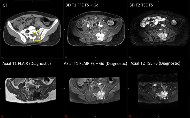
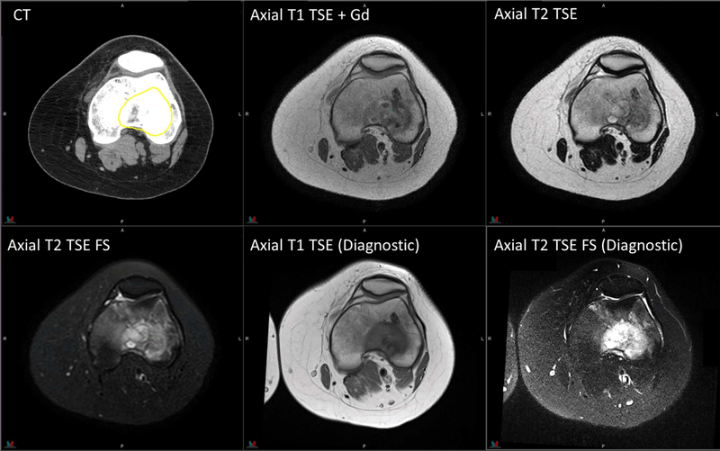
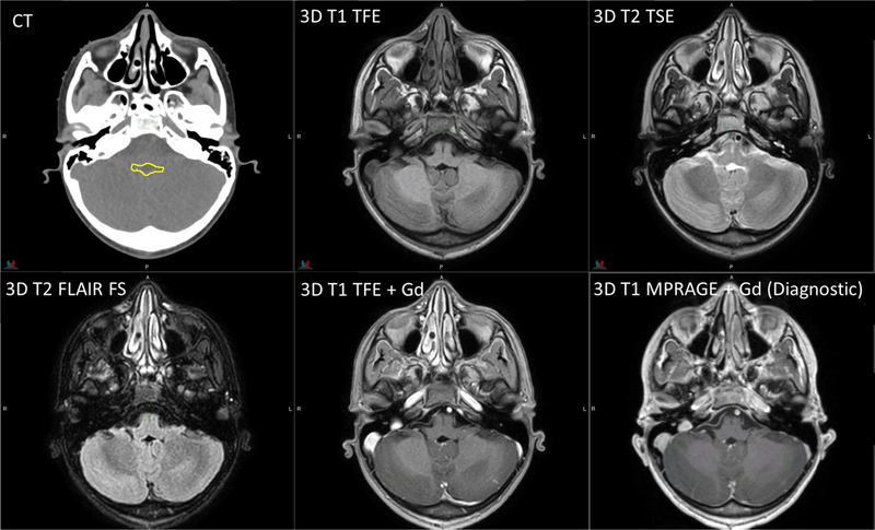
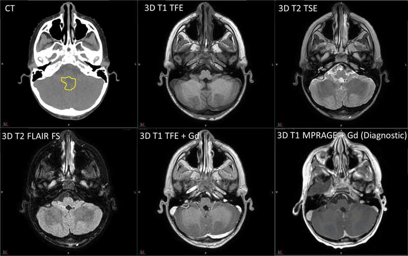
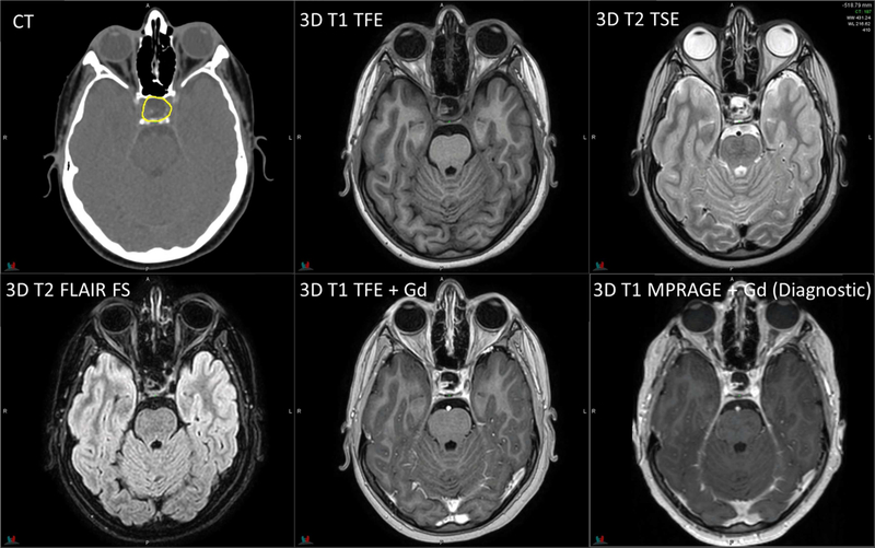
Figures 2 to 6 show multi-sequence planning MR images of representative patients with the five tumor types most commonly imaged in our department. These images were acquired with the patients in their treatment positions on a 1.5T Philips MRI system. For comparison purposes, we also show brain images obtained with a 3D T1 MPRAGE sequence and body images acquired with appropriate sequences in the diagnostic radiology department on Siemens MRI systems with a dedicated head coil or combined body and spine coils. All diagnostic images were acquired with a 3T system (MAGNETOM Prismafit), except for those of Ewing sarcoma in the knee, for which a 1.5T system (MAGNETOM Avantofit) was used. The gross tumor volume contours are overlaid on the CT images. Note that the MRI sequences on the diagnostic radiology systems were optimized for diagnostic purposes; therefore, the scan parameters, slice spacing/thickness and angulation, and FOV differ from those used with the MRI systems in the radiation oncology department, which unfortunately prevents a fair quantitative comparison of the image quality.
Figure 2.
Planning CT and MR images of an 11-year-old patient with infratentorial ependymoma. 3D T1 TFE: TR/TE = 8/3.5 ms, 1 average, flip angle = 8°, 2-mm slice thickness. 3D T2 TSE: TR/TE = 2500/229 ms, flip angle = 90°, 3 averages, 2-mm slice thickness. 3D T2 FLAIR with fat saturation: TR/TE = 4800/316 ms, 2 averages, 2-mm slice thickness. Diagnostic 3D T1 MPRAGE: TR/TE/TI = 1800/2.26/900 ms, flip angle = 9°, 1 average, 1-mm slice thickness. The yellow contour on CT represents the gross tumor volume.
Figure 6.
Planning CT and MR images of a 17-year-old patient with Ewing sarcoma in the knee. Axial T1 TSE: TR/TE = 570/8.5 ms, flip angle = 90°, 1 average, 3-mm slice thickness. Axial T2 TSE without fat saturation: TR/TE = 4178/100 ms, flip angle = 90°, 2 averages, 3-mm slice thickness; with fat saturation: TR/TE = 4433/60 ms. Diagnostic axial T1 TSE: TR/TE = 770/7.7 ms, flip angle = 180°, 2 averages, 5-mm slice thickness. Diagnostic axial T2 TSE with fat saturation: TR/TE = 4500/94 ms, flip angle = 180°, 1 average, 5-mm slice thickness.
We compared the grey-white matter contrast with the 1.5T and 3T Philips MRI systems, using the available RT coils for six pediatric patients with brain tumors (ependymoma, medulloblastoma, pilocytic astrocytoma, optic pathway glioma, germinoma, and glioblastoma multiforme). The contrast was measured on the superior temporal gyrus of T1-weighted images because of the large white-matter bundle. The contrast-to-noise ratio, defined as the difference between the intensities of grey matter and white matter divided by the root mean square of individual standard deviations, was 5%–22% higher for the 3T system. Three radiation oncologists reviewed the 1.5T and 3T T1-weighted, T2-weighted, and FLAIR images of the six patients side by side. Although the 1.5T and 3T images were acquired on different days, the same imaging parameters and imaging extent were used in each case. The physicians reported that the 3T system had superior performance in the following areas: delineation of cranial nerves and dural/meningeal surfaces; delineation of areas of residual disease (most apparent in the case of ependymoma at the cranio-cervical junction) and the margins of gross disease (as in the pilocytic astrocytoma and germinoma cases); and grey-white matter differentiation of cerebellar folia. For tumors that have undergone gross total resection, 3T MRI may provide less of an advantage when compared to 1.5T MRI. The physicians also observed increase in chemical shift, susceptibility, and flow artifacts near the brainstem in the 3T cases. Chemical shifts may exaggerate some structures potentially resulting in a difference in contour location at cerebrospinal fluid-brain interfaces.
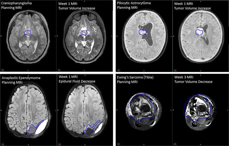
MRI acquired during the treatment course was prescribed based on clinical need by individual treating radiation oncologists. Images were acquired using a subset of planning sequences, >95% without contrast administration. The main purpose of this imaging is to detect changes in the tumor and surgical cavity during the treatment course caused by cyst expansion, tumor progression, cavity volume dynamics after resection, or tumor position shift due to hydrocephalus. Other purposes include monitoring potential early treatment effects on normal tissues and anatomic variations along the proton beam paths that might affect the tumor coverage. Craniopharyngioma, ependymoma, pilocytic astrocytoma, Ewing sarcoma, and rhabdomyosarcoma are top 5 tumor types most imaged during RT courses. The examples in Fig 7 demonstrate that the image quality of on-treatment MRI acquired in the RT configuration is sufficient for the appreciation of anatomic changes.
Figure 7.
Planning and on-treatment MR images of patients replanned during the RT course. Dark-blue contours of original gross tumor volumes are overlaid on registered on-treatment MR images.
DISCUSSION
Having direct access to dedicated MRI systems has facilitated our visualization of both intact tumors and resected tumor cavities at the time of RT. For intact central nervous system tumors and musculoskeletal soft-tissue tumors, we used MRI to delineate the boundary of the gross tumor and peritumoral edema, which is not always discernible on CT images. For patients who underwent tumor resection, MRI was helpful in defining the clinical target volume by enabling clear visualization of the resection cavity. It also provided valuable information on possible tumor spread along white-matter tracts or fascial planes, invasion of bones and joints, and involvement of neuromuscular bundles.11 MRI was also routinely used in our clinic to help identify critical organs to be avoided, such as the optic chiasm and brainstem of patients undergoing intracranial RT and the ovaries of patients undergoing pelvic RT or craniospinal irradiation. MRI during the RT course is helpful for detecting cyst expansion,12–14 which may necessitate replanning. MRI provides a non-ionizing approach to monitoring anatomic changes in the beam path and the inter-treatment consistency of respiration-induced tumor motion.
Several techniques developed for pediatric diagnostic MRI may be applicable for further improving imaging for RT. Ultrafast and k-space oversampling techniques can be used to decrease movement artifacts in pediatric brain imaging,15 and various motion-compensation techniques are available for pediatric abdominal MRI.5 When imaging pediatric body tumors that are weakly enhancing even after gadolinium administration, adjusting the pulse sequence parameters (TR, TE, TI) and completing a fast acquisition in the arterial or porto-venous phase may improve the tumor boundary detection.16 Although 3T systems generally provide a higher SNR than that obtained with 1.5T systems, attention should be paid to altered T1 contrast resulting from T1 lengthening, increased magnetic field heterogeneity, increased susceptibility effects, and the MR safety status of implants.4 Increased specific absorption rate and peripheral nerve stimulation must be considered when manipulating the protocol parameters.
It is well known that changing scan parameters by operators for individual patients could impact the consistency of image quality and how clinicians interpret the images. For example, both decreasing the number of averages and decreasing the matrix size reduce the scan time but the former decreases the SNR while the latter increases the SNR at the expense of resolution. Our clinical practice is to have technologists make only minor adjustments in the field of view and longitudinal scan coverage if needed without “optimizing” the sequence on the fly. Vendor also provided training on effects of changing individual scan parameters. For children who are anxious and less cooperative, child life specialists or parents would accompany and comfort the patient during imaging rather than having technologists reduce the scan time by adjusting parameters.
Because commercially available MRI systems aimed at radiation oncology users are merely adaptations of diagnostic scanners, some improvements are desirable. Increasing the intensity uniformity by redesigning the flexible coils used for head imaging while making accommodation for masks would further improve the image quality. Ideally, high-quality physiologic and metabolic MRI (e.g., spectroscopy imaging) could be acquired along with anatomic imaging using the RT coils, thus avoiding the need for extra time to switch coils and reposition patients. Decreasing the coil-to-patient distance by integrating the posterior coil elements into the flat table top could increase the SNR. The total imaging time for treatment planning (excluding the time for patient setup) is typically 20–30 min, depending on the number of sequences and the FOV. Faster acquisition by using k-space undersampling and compressed sensing reconstruction could reduce the use of anesthetics and/or increase the ability of conscious children to comply with the procedure requirements. We could adapt the imaging positions of our pediatric patients when switching from an open MRI system to the closed and wide-bore systems. However, the 70-cm bore could still be limiting for certain positions and setup devices used with large adolescent patients. Lastly, it is desirable that the daily quality-assurance phantom and the tested coils be used together with the flat table top; avoiding time-consuming swapping of the flat and curved table tops will reduce the staff workload.
MR-only simulation is not currently performed in our department. Instead, patients are transported to the adjacent MR suite after CT simulation and are set up for MRI based on reference surface marks drawn earlier. MRI-based isocenter marking can be accomplished by sending images from the MR console to the MIM software, marking the isocenter point, and exporting the coordinates to the LAP laser computer. Methods for synthesizing CT images from MRI have also been developed for pediatric patients with brain tumors who are receiving photon therapy.17 However, challenges to adopting MR-only simulation remain. Our image guidance software does not support planning MRI or synthetic CT for registration with on-treatment cone-beam CT, and the accuracy of the MRI-based dose calculation in children has not been determined outside the brain. For proton therapy patients, the current priority is to further improve the accuracy of stopping-power estimation with spectral CT, rather than introduce additional uncertainty via MR-based planning.
CONCLUSIONS
We have described the clinical implementation of the MRI systems in our department. Our use of the posterior coil beneath the flat table top in conjunction with the flexible loop coils or the “hanging” anterior coil allows patients to maintain their treatment positions during imaging. MRI of pediatric patients in their treatment positions can yield images of sufficient quality for treatment planning and on-treatment monitoring. We have provided the parameters of our optimized site-specific sequences for the benefit of facilities implementing MR simulation for pediatric patients.
Figure 3.
Planning CT and MR images of a 6-year-old patient with medulloblastoma. RT sequence parameters are identical to those in Figure 2. Diagnostic 3D T1 MPRAGE: TR/TE/TI = 1980/2.26/1100 ms, flip angle = 15°, 1 average, 1-mm slice thickness.
Figure 4.
Planning CT and MR images of a 12-year-old patient with craniopharyngioma. RT sequence parameters are identical to those in Figure 2. Diagnostic 3D T1 MPRAGE: TR/TE/TI = 1560/2.74/900 ms, flip angle = 15°, 1 average, 1-mm slice thickness.
Figure 5.
Planning CT and MR images of a 15-year-old patient with rhabdomyosarcoma. 3D T1 FFE with fat saturation: TR/TE = 4.5/2.2 ms, flip angle = 10°, 4 averages, 2.4-mm slice thickness. 3D T2 TSE with fat saturation: TR/TE = 2000/191 ms, flip angle = 90°, 2 averages, 2.4-mm slice thickness. Diagnostic axial T1 FLAIR with/without fat saturation: TR/TE/TI = 3250/9.4/1000 ms, flip angle = 140°, 1 average, 3-mm slice thickness. Diagnostic axial T2 TSE with fat saturation: TR/TE = 4930/93 ms, flip angle = 150°, 2 averages, 3-mm slice thickness.
ACKNOWLEDGMENTS
This research was partly funded by ALSAC. We thank David Brazzle and Gregory Thomas of Philips Healthcare for acceptance testing, Trey White and Jerry Wyner for support in optimizing pulse sequences, and Keith A. Laycock, PhD, ELS, for scientific editing of the manuscript.
Conflicts of Interest Notification
C.H. acknowledges research collaboration with Philips Healthcare. M.K. is currently employed by Philips Healthcare.
Footnotes
Publisher's Disclaimer: This is a PDF file of an unedited manuscript that has been accepted for publication. As a service to our customers we are providing this early version of the manuscript. The manuscript will undergo copyediting, typesetting, and review of the resulting proof before it is published in its final form. Please note that during the production process errors may be discovered which could affect the content, and all legal disclaimers that apply to the journal pertain.
REFERENCES
- 1.Lagendijk JJ, Raaymakers BW, Van den Berg CA, et al. MR guidance in radiotherapy. Phys Med Biol. 2014;59(21):R349–R369. [DOI] [PubMed] [Google Scholar]
- 2.Acharya S, Fischer-Valuck BW, Kashani R, et al. Online magnetic resonance image guided adaptive radiation therapy: first clinical applications. Int J Radiat Oncol. 2016;94(2):394–403. [DOI] [PubMed] [Google Scholar]
- 3.Tryggestad E, Flammang A, Han-Oh S, et al. Respiration-based sorting of dynamic MRI to derive representative 4D-MRI for radiotherapy planning. Med Phys. 2013;40(5):051909. [DOI] [PubMed] [Google Scholar]
- 4.Dagia C, Ditchfield M. 3T MRI in pediatrics: challenges and clinical applications. Eur J Radiol. 2008;68:309–319. [DOI] [PubMed] [Google Scholar]
- 5.Chavahan GB, Babyn PS, Vasanawala SS. Abdominal MR imaging in children: motion compensation, sequence optimization, and protocol organization. Radiographics. 2013;33:703–719. [DOI] [PubMed] [Google Scholar]
- 6.Tocchio S, Kline-Fath B, Kanal E, et al. MRI evaluation and safety in the developing brain. Semin Perinatol. 2015;39(2):73–104. [DOI] [PMC free article] [PubMed] [Google Scholar]
- 7.Mah D, Steckner M, Palacio E, et al. Characteristics and quality assurance of a dedicated open 0.23 T MRI for radiation therapy simulation. Med Phys. 2002;29(11):2541–2547. [DOI] [PubMed] [Google Scholar]
- 8.Devic S. MRI simulation for radiotherapy treatment planning. Med Phys. 2012;39(11):6701–6711. [DOI] [PubMed] [Google Scholar]
- 9.]Uh J, Khan MA, & Hua C (2016). Four-dimensional MRI using internal respiratory surrogate derived by dimensionality reduction. Phys Med Biol 61(21), 7812–7832 [DOI] [PubMed] [Google Scholar]
- 10.]Uh J, Krasin MJ, & Li Y, et al. (2017). Quantification of pediatric abdominal organ motion with a 4-dimensional magnetic resonance imaging method. Int J Radiat Oncol Biol Phys 99(1), 227–237 [DOI] [PMC free article] [PubMed] [Google Scholar]
- 11.McCarville MB. Imaging techniques used in the diagnosis of pediatric tumors. In: Parham DM, Khoury JD, McCarville MB, eds. Pediatric Malignancies: Pathology and Imaging. New York, NY: Springer Publishing; 2015:7–18. [Google Scholar]
- 12.Winkfield KM, Linsenmeier C, Yock TI, et al. Surveillance of craniopharyngioma cyst growth in children treated with proton radiotherapy. Int J Radiat Oncol Biol Phys. 2009;73(3):716–721. [DOI] [PubMed] [Google Scholar]
- 13.Beltran C, Roca M, Merchant TE. On the benefits and risks of proton therapy in pediatric craniopharyngioma. Int J Radiat Oncol Biol Phys. 2012;82(1):e281–e287. [DOI] [PMC free article] [PubMed] [Google Scholar]
- 14.Lamiman K, Wong KK, Tamrazi B, et al. A quantitative analysis of craniopharyngioma cyst expansion during and after radiation therapy and surgical implications. Neurosurg Focus. 2016;41(6):E15. [DOI] [PubMed] [Google Scholar]
- 15.Woodfield J, Kealey S. Magnetic resonance imaging acquisition techniques intended to decrease movement artefact in paediatric brain imaging: a systematic review. Pediatr Radiol. 2015;45(9):1271–1281. [DOI] [PubMed] [Google Scholar]
- 16.Olson ØE. Practical body MRI—a paediatric perspective. Eur J Radiol. 2008;68:299–308. [DOI] [PubMed] [Google Scholar]
- 17.Uh J, Merchant TE, & Li Y, et al. (2014). MRI-based treatment planning with pseudo CT generated through atlas registration. Med Phys 41(5), 051711, 10.1118/1.4873315. [DOI] [PMC free article] [PubMed] [Google Scholar]


