Abstract
Purpose:
The purpose of this study is to introduce a new antenna element with improved transmit performance, named the non-uniform dielectric substrate (NODES) antenna, for building transmit arrays at ultra-high field (UHF).
Methods:
We optimized a dipole antenna at 10.5 T by maximizing the B1+-SAR efficiency in a phantom for a human spine target. The optimization parameters included permittivity variation in the substrate, substrate thickness, antenna length, and conductor geometry. We conducted EM simulations as well as phantom experiments to compare the transmit and receive performance of the proposed NODES antenna design with existing coil elements from the literature.
Results:
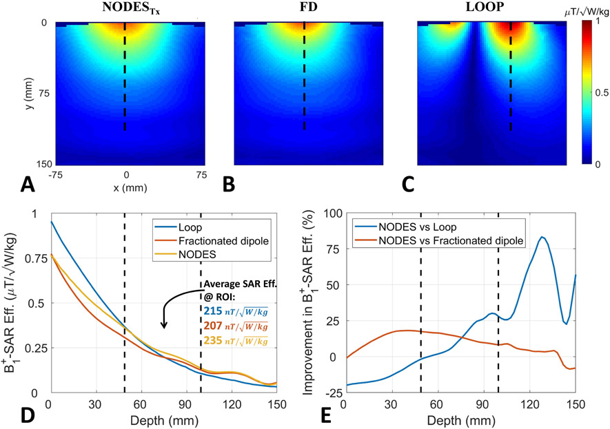
Single NODES element showed up to 18% and 30% higher B1+-SAR efficiency than the fractionated dipole and loop elements, respectively. The new element is substantially shorter than a commonly-used dipole, which enables z-stacked array formation and it is additionally capable of providing a relatively uniform current distribution along its conductors. The nine-channel transmit/receive NODES array achieved 7.5% higher B1+- homogeneity than a loop array with the same number of elements. Excitation with the NODES array resulted in 33% lower peak 10g-averaged SAR (pSAR10g) and required 34% lower input power than the loop array for the target anatomy of the spine.
Conclusion:
In this study, we introduced a new RF coil element, the non-uniform dielectric substrate (NODES) antenna. NODES antenna outperformed the widely-used loop and dipole elements and may provide improved transmit and receive performance for future UHF-MRI applications.
Keywords: MRI, Ultra-high field, 10.5 tesla, NODES, Radiofrequency Safety, Spine Imaging
Introduction
Various advantages of ultrahigh-field (UHF, B0 ≥ 7 T) MRI, including an increase in SNR [1-6] and enhancement in susceptibility contrast (e.g., [7-9]), are drawing significant attention in many clinical and research applications such as anatomical imaging (e.g., [8-14]), functional MRI studies [15-17], etc. Despite the benefits of UHF MRI, a higher magnetic field (B0) requires using radiofrequency (RF) excitations with shorter electromagnetic (EM) wavelengths, results in highly variant excitation profiles, and consequently, degradation in overall image quality. On the other hand, constructive interference of the RF electric field can cause high local specific absorption rate (SAR) levels, which is the predominant safety concern at UHF MRI. Transmit arrays (TxArrays) tackle both these issues (e.g., [18-24]) by providing flexibility on RF magnetic and electric fields. Still, arranging elements of a transmit array in both the transverse and longitudinal directions, which is critical for mitigating the excitation inhomogeneity in some applications (e.g., spine imaging [25-29]), faces some technical difficulties due to the physical size of an RF coil’s elements as well as EM interactions (i.e., coupling) between them [29].
In the literature, different types of coil elements are proposed, including the transmission line (TL) [18 30-33], loop coil [25-27 34-36], and dipole-like structures [3 37-43] which are used to compose TxArrays for UHF MRI applications. For example, Adriany et al. [44] designed and built a single-row 16-channel TL array for head imaging at 7 T. They employed capacitive decoupling for the nearest neighbors and exploited the advantage of a shield for decoupling the next-nearest neighbors. Later, Shajan et al. [35] used inductive decoupling for the nearest neighbors and stacked loop elements in both transverse and longitudinal directions to design a dual-row 16-channel TxArray for 9.4T head imaging. Nevertheless, a few experimental and numerical studies demonstrated that dipole elements could be advantageous over loop and TL elements. For example, a numerical study by Lattanzi et al. [45] suggested that the ideal current distribution at higher field strengths tends to be similar to that of electrical dipoles. In a different study [38] the single-side adapted dipole antenna outperformed the loop and stripline elements in terms of B1+-power and B1+-SAR efficiency in some applications (e.g., organ of interest is in-depth) at 7 T. Another study demonstrated that the dipoles can be inherently decoupled by placing them at a proper distance from each other without using further decoupling methods [3], which is an advantage over conventional loop designs.
Raaijmakers et al. [39] introduced the fractionated dipole, an inductively shortened dipole (~30cm) without sacrificing its transmit performance, for body imaging at 7 T. Later, several studies were performed to improve the B1+-SAR efficiency of the dipole by altering its geometry (e.g., snake antenna [40 46]), spatial positioning [41 47], and resonant nature [48]. Duan et al. [29] used two dipoles (i.e., arranged in transversal direction) along with four loops (arranged in z-direction) as transmitters for spine imaging at 7T. The dipoles were not stacked in z-direction due to their length (~25cm). Erturk et al. combined this structure with loops for 7 T body imaging [49], and also, re-designed the fractionated dipole to have a physical length of ~20cm, and arranged a 10-channel single-row TxArray for 10.5 T torso imaging [3]. It is also shown that adding high-permittivity pads underneath the RF coil can increase its transmit and receive performances [50-52]. Ozerdem et al. [37] proposed to use a short bowtie antenna (~15cm) immersed into a high-permittivity material (de-ionized D2O) and designed a dual-row 16-channel TxArray for cardiac imaging at 7 T. Bowtie antenna had a shorter length compared to other dipole antennas previously proposed for MRI, therefore it allowed distributing Tx elements in the longitudinal direction. Its conductor configuration increased power transmission stability with respect to different loading conditions. However, its impact on B1+-power and B1+-SAR efficiencies was not investigated. In addition, the strategy of using D2O to shorten the effective length of the antenna introduced other potential problems, including increased weight per element and pronounced EM losses at higher frequencies (i.e., > 400 MHz).
In this study, we propose a new dipole-like antenna [53], utilizing NOn-uniform DiElectric Substrate (NODES) placed underneath the element. This modification enables us to effectively decrease the length of a commonly-used dipole while increasing the uniformity of the current distribution on the dipole and reducing local SAR. Due to its short length, NODES antennas can be stacked around the body longitudinally as well as circumferentially in order to cover large anatomies of interest.
In order to design the NODES antenna, we optimized the geometry of a dipole-like element at 10.5 T using EM simulations. The optimization parameters included permittivity variation of the substrate, substrate thickness, antenna length, and conductor geometry. We evaluated the B1+-power efficiency and B1+-SAR efficiency of the proposed design and compared it to the fractionated dipole [3] and loop [54] in EM simulations. We also conducted phantom imaging experiments at 10.5 T and compared the power efficiencies and 10g-averaged SAR distributions of the same elements, thereby validating our EM simulations.
In addition, we compared Tx/Rx arrays consisting of NODES and loop elements for spinal cord imaging, evaluating power requirements and peak local SAR performance. Finally, we acquired human cadaver images using the proposed NODES array at 10.5 T and demonstrated its imaging performance.
Theory
Decreasing the length of a dipole forces the current to rapidly decrease towards the ends (i.e., current vanishes at two ends of the dipole due to the high impedances at these points). To analyze the consequences of this phenomenon, we assume the dipole in Figure 1A as a perfect electric conductor (PEC) in the vicinity of a lossy medium (e.g., human body) and investigate the following Maxwell’s equation and boundary conditions [55]
| (1) |
| (2) |
| (3) |
where is the unit vector normal to the PEC boundary, is the magnetic field intensity, and is the surface current density. For the configuration in Figure 1A, Equation 2 leads to
| (4) |
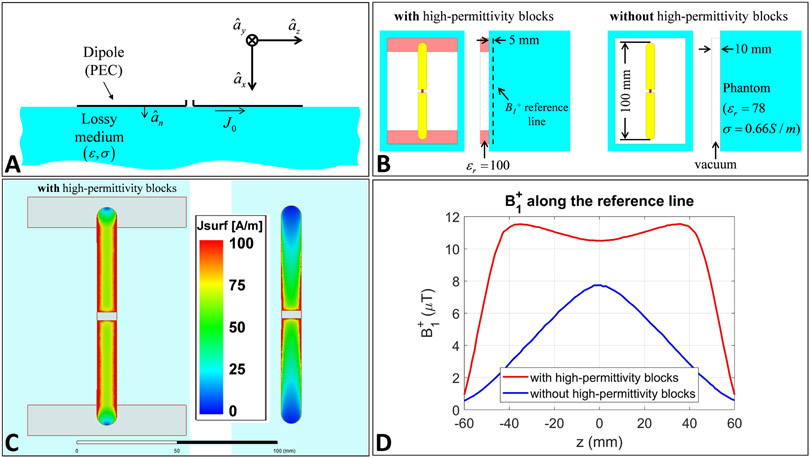
Figure 1.
Adding high-permittivity blocks to a short dipole. (A) Configuration used to solve Equations 1 through 3, (B) Simulation set-ups corresponding to a short dipole with and without the high-permittivity blocks, (C) Distributions of the surface current density on the two dipoles, and (D) B1+ on z-directed reference line, 5mm away from surface of the phantom and 15mm away from the dipole, generated by a unit current distribution.
Elaborating Equation 3 and substituting the corresponding value from Equation 4 result in the following,
| (5) |
The field can be obtained by substituting the field from Equation 5 into Equation 1 as follows
| (6) |
Therefore, based on Maxwell’s equations, when the current rapidly changes along the conductor (z-direction), the transverse electric field and therefore SAR in the tissue are elevated as a result.
Placing high-permittivity blocks at two ends of the dipole can potentially increase the effective capacitance between these points and the body. As a result, the corresponding impedance can be decreased. This effect, in turn, increases the uniformity of the current on the dipole and reduces the electric field. Also, the B1+ generated by this current becomes considerably more uniform in the z-direction. This concept is demonstrated as an example in Figure 1B-D using EM simulations. For this purpose, a finite element method-based frequency domain EM simulator (HFSS, ANSYS, Canonsburg, PA, USA) is used to simulate two short dipoles (10cm) in close proximity (1cm-apart) of a lossy phantom (εr = 78, σ = 66 S/m) at 447 MHz (i.e., the Larmor frequency at 10.5T); one with the high-permittivity blocks (εr = 100), and the other without the blocks (Figure 1B). Both dipoles are excited using unit current sources at the middle. The surface current densities corresponding to the two dipoles are shown in Figure 1C. Figure 1D shows the B1+ fields of the dipoles along a z-directed line, 5mm away from surface of the phantom (dashed line in Figure 1B).
In addition, it has been previously shown that placing a high-permittivity material (HPM) underneath the entire transmitter element can increase the magnetic field’s penetration depth [50 51 56].
To balance these potential benefits, we numerically optimized several design parameters.
Methods
Numerical Optimization of the NODES Antenna's parameters
To determine the optimum design parameters, a relatively deep-body target (e.g., spine imaging) is defined. The dipole is optimized by considering six design parameters including conductor length (l), conductor width at two end-points (w), distance or height between the conductor and sample (h), dielectric constants of the segmented substrate (εr1, εr2, εr3)). We set the following optimization goal to maximize the B1+-SAR efficiency at depths of 50 to 100 mm from the posterior surface of the body.
Where ξ(r) represents the B1+-SAR efficiency at the position r and is defined as
where pSAR10g is the peak local 10g-averaged SAR over the entire load.
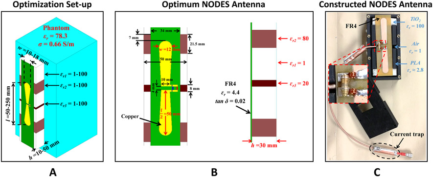
A commercial EM simulator (HFSS) was used to simulate coil elements. We performed an exhaustive search over the results obtained from fast, coarsely meshed EM simulations (i.e., ~2×10⁴ tetrahedrons implemented by the EM solver using an iterative mesh refinement approach with 10−2 ΔS stop criterion). As a result of the optimization, a NOn-uniform DiElectric Substrate (NODES) antenna was designed. Figure 2A shows the structure we used for the optimization purpose as well as the ranges for each parameter. A cubic phantom with relative permittivity of 78.3 and conductivity of 0.66 S/m was used to mimic the human body. Figure 2B shows the optimum values of the investigated parameters (i.e., l, w, h, εr1, εr2, εr3).
Figure 2.
NODES antenna. (A) The structure of the NODES antenna and the ranges assumed for the optimization parameters are shown. (B) The NODES antenna with the optimal parameters. (C) The constructed NODES antenna.
For the experimental set-up, we employed a high-dielectric constant block made of TiO2 (εr=100, σ=1.1 mS/m), designed and manufactured in the Department of Engineering Science and Mechanics at the Pennsylvania State University, to construct the NODES antenna. 30mm-thick housing of the NODES antenna was 3D-printed using polylactic acid (PLA) material with εr≈2.8, σ=0.1 mS/m. Eventually, the element shown in Figure 2C with 420g weight was built, and the simulations were validated experimentally.
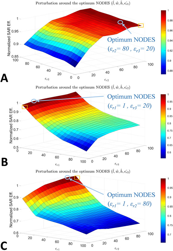
Comparing the optimum values (see Figure 2B) to the values used to build the experimental set-up (see Figure 2C), apparent discrepancies exist in permittivity values (i.e., εr1, εr2, εr3) due to some practical concerns (e.g., availability of the material with the exact permittivity value). To ensure that such deviations from the optimum values do not harm the overall performance of the NODES antenna, we perturbed εr1, εr2, and εr3 as pairs around the optimum point (see Figure 3) and evaluated the SAR performance. In other words, in each case (Figure 3A-C), l, w, h, and one of the εr’s were kept as their optimum values, then two other εr’s were swept within the search interval. The plots in Figure 3 show the alteration of B1+-SAR efficiency with εr’s normalized to its optimal value. In each plot, the blue circle indicates the optimum point and the yellow square points to the experimentally used values. Consequently, deviating from the optimal NODES antenna leads to only a 3% reduction in the B1+-SAR efficiency.
Figure 3.
Spatially varying permittivity impacts B1+-SAR efficiency of the NODES Antenna. For A, B, and C εr1, εr2, and εr3 were assigned their optimal values, respectively, whereas the other two εr’s were swept within the search interval. The blue circle indicates the optimum point, and the yellow square points to the experimentally used values.
Single-Element Comparison
A single-element comparison was performed between the NODES antenna, fractionated dipole (FD) [3], and loop coil [54], as shown in Figure 4A. For this purpose, a torso-sized elliptical body phantom (450 × 180 × 290 mm3) [57] filled with hydroxyethyl cellulose (HEC) and 2.9 g/L NaCl with electrical properties of εr=78 and σ=0.66 S/m was used. The fractionated dipole and loop coil consisted of conductors on an FR4 PCB mounted on a PETG block with a thickness of 20 mm and 10 mm, respectively. Two series hand-wound inductors along with a parallel variable capacitor were used for tuning and matching the NODES element. To match the FD and loop elements, first-order lattice balun networks were utilized. In addition, the loop element was segmented using eight identical fix capacitors to mitigate current nonuniformity along the conductor. All three elements were matched to 50 Ω with a reflection coefficient of less than −15 dB.
Figure 4.
(A) The NODES antenna, a fractionated dipole (FD), and a loop coil were placed on an elliptical uniform phantom and compared to each other in terms of the transmission performance. (B) The NODES antenna and a fractionated dipole (FD) were used in the MRT experiment as well as the 10g-averaged SAR simulation to validate the numerical results.
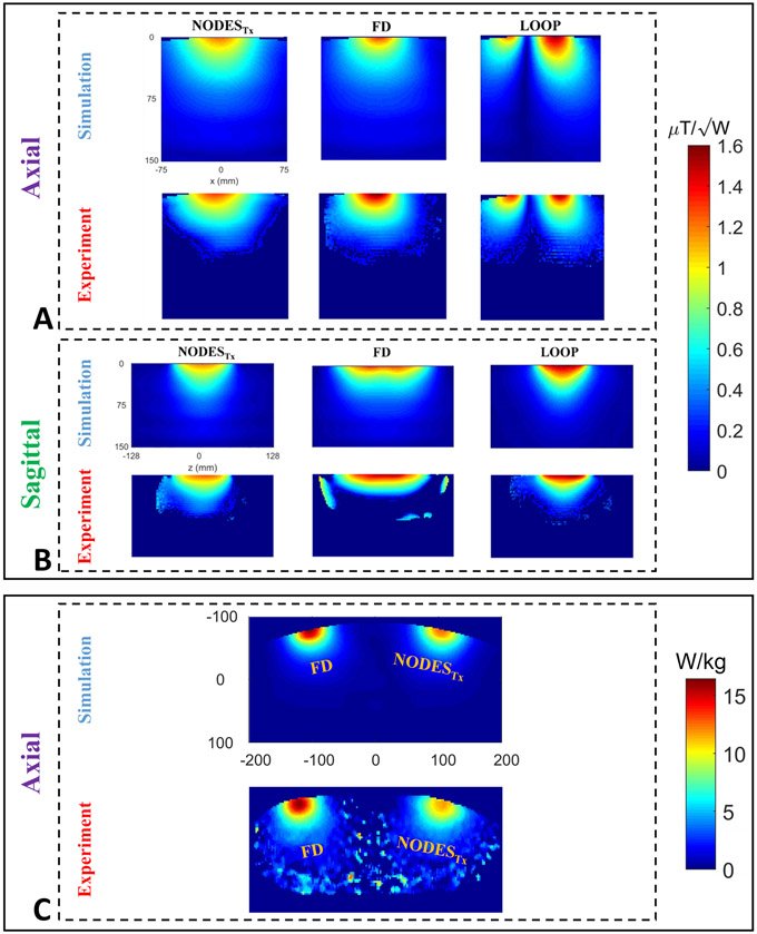
To validate the numerical results, the same three elements in Figure 4A (except the FD was mounted on a 10mm-thick block) were used, and B1+-power efficiency (B1+/√Pin) maps were acquired numerically and experimentally on both axial and sagittal planes. Furthermore, a set-up (see Figure 4B) consists of a NODESTx and an FD placed on the elliptical body phantom was utilized to map the 10g-averaged SAR distributions numerically and experimentally on an axial plane.
All computations and numerical simulations were performed using a commercial EM simulator (HFSS) on a workstation with two quad-core Intel(R) processors with a 3.4 GHz clock rate and 128 GB RAM.
Experimental studies with the above set-up were conducted in a whole-body 10.5 T Magnet (Agilent Technologies, Oxford, UK) and associated imaging system (Siemens Healthineers, Erlangen, Germany). The scanner is equipped with a 16-channel parallel transmit system with each channel driven by a 2-kW RF power amplifier (Stolberg HF-Technik AG, Stolberg, Germany). Transmit B1+ maps were acquired using the actual flip-angle imaging (AFI) technique [58]. Temperature mapping was performed using magnetic resonance thermometry (MRT) [59] based on the proton resonance offset method [60] with a 3D multi-echo gradient-echo sequence. 10g-averaged SAR values were calculated by finding the slope of the initial part of the heating curve and multiplying with the heat capacity of the HEC gel (4386 J/kg/°C).
To show the improved local SAR performance of the NODES antenna compared to the FD and the loop coil, the peak 10g-SAR efficiencies of the three structures were numerically computed using EM simulations of the validated models. Furthermore, we slightly modified the NODES antenna by reducing patient-coil-separation (20 mm) to enhance its reception performance.
TxArray Comparison
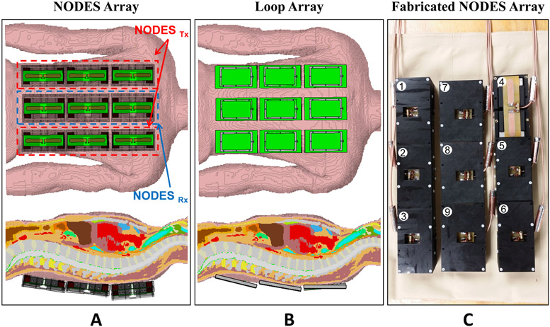
Nine-channel spine arrays consisting of NODES antennas and loops were compared through EM simulations (Figure 5). For both arrays, elements were conformed to the posterior surface of a realistic human body model (Duke, voxel size 2×2×2 mm3). The NODES array consisted of six NODES antennas with the 30mm-thick block (i.e., NODESTx, optimized for local SAR efficiency) and three NODES antenna with the 20mm-thick block (i.e., NODESRx, improved SNR performance). The loop array consisted of the loop elements shown in Figure 4A. For both arrays, all elements served as transceiver elements.
Figure 5.
Numerical and experimental evaluation of a nine-channel Tx/Rx NODES spine array. EM simulation set-up of the nine-channel Tx/Rx (A) NODES and (B) loop spine array in the presence of a realistic human body model (Duke). (C) The custom-made nine-channel Tx/Rx NODES spine array. The columns at right and left are composed of NODESTx elements, whereas the middle column is composed of NODESRx.
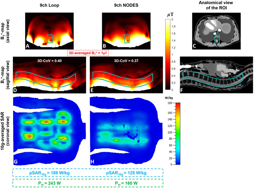
An FIT (finite integration technique)-based time-domain solver of an EM simulator, CST Studio Suite 2019 (CST, Darmstadt, Germany), was used for the simulations. Employing the EM field solutions from the two arrays (Figure 5), we performed phase-only RF shimming to achieve maximum excitation homogeneity for an average B1+ of 1 μT over the spine. Then the coefficient of variation (CoV) of the resulting B1+ distribution, average B1+ value, and pSAR10g were calculated.
The nine-channel NODES antenna array, shown in Figure 5C, was built to be used for spine imaging at 10.5 T. All elements were matched to better than −9.5 dB, and the highest coupling between the elements was −12.5 dB. Two floating current traps were used on each coaxial cable connected to feed-points to prevent the unbalanced current flow on the outer conductors.
Human Cadaver Spine Imaging
Human cadaver images were collected following guidelines from Anatomy Bequest Program (ABP) review committee. We performed phase-only RF shimming [19] with the goal of maximum B1+ homogeneity over the spine (defined by user-drawn ROI) in both the simulation environment and the cadaver experiment.
We acquired sagittal images using the FLASH pulse sequence with FA = 20°, TR/TE = 168 ms/3.69 ms, in-plane resolution = 0.5 mm, slice thickness = 2 mm, acquisition matrix = 576×432, # of averages = 2, and pixel bandwidth = 212 Hz/pixel. In addition, T2*-weighted axial images were acquired using a multi-echo data image combination (MEDIC) pulse sequence with FA = 30°, echo train length = 4, TR/TE = 500 ms/19 ms, in-plane resolution = 0.24 mm, slice thickness = 2 mm, acquisition matrix = 640×640, # of averages = 4, and pixel bandwidth = 244 Hz/pixel. We also acquired turbo spin-echo (TSE) images with refocusing FA = 120°, TR/TE = 5000 ms/56 ms, in-plane resolution = 0.5 mm, slice thickness = 2 mm, acquisition matrix = 640 × 480, TSE-factor 9, # of averages = 1, and pixel bandwidth = 313 Hz/pixel.
Results
Single-Element Comparison
Figures 6A and 6B show the B1+-power efficiency of the three transmit elements (i.e., NODESTx antenna, FD, and loop coil) on axial and sagittal planes. Figure 6A represents the axial view of the numerical and experimental results, whereas Figure 6B corresponds to the sagittal view of the B1+-power efficiency maps. In addition, numerically simulated and experimentally measured 10g-averaged SAR maps are given in Figure 6C. A good agreement between the simulation and experimental results is achieved.
Figure 6.
Validation of the numerical results. (A-B) Axial and sagittal B1+-power efficiency maps, and (C) axial 10g-averaged SAR maps of the three transmit elements were obtained numerically and experimentally.
Figure 7A-C show the axial B1+-SAR efficiency maps of the three transmit elements obtained using the EM simulations. Comparing the SAR performance of these elements with increasing distance, Figure 7D demonstrates the corresponding B1+-SAR efficiencies plotted over the dashed lines shown in Figure 7A-C Improvement in B1+-SAR efficiency of the NODESTx antenna with respect to the fractionated dipole and loop coil is shown in Figure 7E. According to Figures 7D and 7E, the NODESTx antenna outperforms both the fractionated dipole and loop coil up to 18% and 30%, respectively, at the depth range between 50 and 100 mm (i.e., the depth-of-interest in the optimization problem). Similarly, the three elements' reception performance is compared through their ISNR plots and presented in the Supporting Information Figure S1.
Figure 7.
B1+-SAR efficiency comparison. Axial B1+-SAR efficiency map of (A) NODESTx antenna, (B) fractionated dipole, and (C) loop coil. The vertical dashed lines in (A-C) show the location of the profiles used in (D-E). (D) B1+-SAR efficiencies of the three structures with increasing distance from the element. (E) Improvement of B1+-SAR efficiency with increasing distance achieved by the NODESTx compared to the fractionated dipole and loop. The vertical dashed lines in (D-E) indicate the start and end ranges over which the NODESTx were optimized and represent the approximate depth of the anatomy of interest (i.e. the spine).
TxArray Comparison
Performing phase-only shimming over a fraction of the lumbar and thoracic spine (see Figures 8C and 8F) as the region-of-interest (ROI), Figures 8A-B and 8D-E show the B1+-maps obtained with the two arrays on an axial and a sagittal plane, respectively. The CoV of B1+ distribution in the ROI achieved by the NODES and Loop arrays were 0.37 and 0.4, respectively. The improvement in the excitation homogeneity by the NODES array was also accompanied by 33% lower pSAR10g compared to the loop array for a given average B1+ value (1 μT) in the ROI. Note that the pSAR10g corresponding to the phase-only shimming solutions has occurred at the surface of the human body model for both arrays as shown in Figures 8G and 8H. On the other hand, comparing the two arrays in terms of power efficiency, the NODES array generated same average B1+ value (1 μT) in the ROI using 34% lower input power (Pin). Evaluating the reception performance of the two arrays, Supporting Information Figure S2 shows the axial and sagittal maps of the relative SNR over the ROI, obtained using the sum-of-square (SoS) technique.
Figure 8.
Comparison of the transmit performance between the nine-channel Tx/Rx loop and NODES spine arrays. A phase-only shimming was performed over a fraction of the lumbar and thoracic spine.
Human Cadaver Spine Imaging
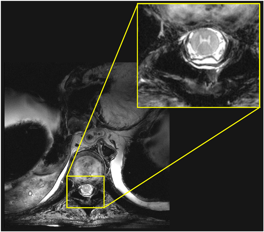
We acquired MR images from a human cadaver at 10.5 T using the NODES antenna spine array. We focused on two basic pulse sequences for these preliminary studies, namely, FLASH and T2*-weighted MEDIC. Figure 9 shows the sagittal view of consecutive cadaver spine images at 10.5 T acquired using the FLASH pulse sequence. Figure 10 shows an axial view of the T2*-weighted cadaver spine image at 10.5 T acquired using the MEDIC pulse sequence. Phase-only shimming [19] was performed to maximize the excitation homogeneity in the spine.
Figure 9.
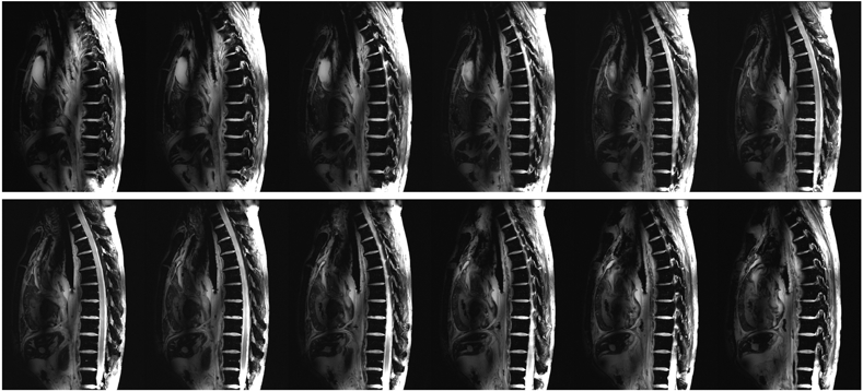
Consecutive sagittal cadaver spine images at 10.5 T acquired using the FLASH pulse sequence with FA = 20°, TR/TE = 168 ms/3.69 ms, Matrix = 576×432, in-plane resolution = 0.5 mm, slice thickness = 2 mm, # of averages = 2, and pixel bandwidth = 212 Hz/pixel.
Figure 10.
A T2*-weighted cadaver spine image at 10.5 T acquired using the MEDIC pulse sequence with FA = 30°, echo train length = 4, TR/TE = 500 ms/19 ms, matrix = 640×640, in-plane resolution = 0.24 mm, slice thickness = 2 mm, # of averages = 4, and pixel bandwidth = 244 Hz/pixel.
Figure 9 shows the sagittal FLASH images, which provided a good tissue contrast between cerebrospinal fluid (CSF) and the spinal cord. Phase-only shimming provided a uniform image intensity over the entire thoracic and lumbar spinal cord. Figure 10 shows an axial MEDIC image acquired at the lumbar spine, which reveals the motor nerve pathway in the spinal cord, including the ventral and dorsal horns. A sagittal view of eight consecutive TSE images is presented in Supporting Information Figure S8.
Discussion and Conclusions
In this study, we introduced the NODES antenna, a short dipole with improved SAR performance mounted on a block with a non-uniform dielectric constant. The design of the NODES antenna enables us to stack the coil elements around the body longitudinally as well as circumferentially in order to cover large anatomies of interest. To prove the concept, we constructed a NODES antenna and compared its transmission performance with the fractionated dipole [3] and loop coil [54] at 10.5 T, numerically and experimentally. Results show that B1+-SAR efficiency can be significantly improved. We built a nine-channel Tx/Rx NODES array and acquired the first cadaver spine MR images at 10.5 T.
Although the impact of placing HPM blocks between the RF coil and imaging object on transmit efficiency, B1 inhomogeneity, SAR, and SNR performance has been previously investigated by optimizing the block’s thickness [50] as well as its permittivity value [56], the idea of altering the permittivity within the HPM block has not been studied. In this work, we considered the permittivity values of a non-uniform block as design parameters.
We performed the optimization process over the pre-defined parameters with the goal of maximum SAR efficiency in deep-body imaging. Consequently, we used the determined values for both Tx and Rx elements. However, they are not necessarily the optimal values for the reception elements. Investigating the optimum Rx elements is beyond the scope of this work and can be considered in future studies as we have partially investigated in [61] for 7T cardiac imaging. The optimum NODESRx for 7T cardiac imaging is shown in Supporting Information Figure S3 and is compared to the FD and loop elements used in the combined loop-dipole block [49]. The results of this comparison in terms of transmission and reception performance in both single-element and TxArray regimes are presented in Supporting Information Figure S3-7.
In this study, both NODESRx and NODESTx elements were used as transceiver elements in spite of their names, which are chosen to discriminate between two elements. In fact, the NODESRx elements have the same design parameters as the NODESTx elements except for the block thickness (h). We decreased the distance between the conductor and sample in NODESRx elements to enhance the SNR. As a result of this modification, single element NODESRx achieves up to 35% and 36% higher SNR in the ROI than single FD and loop elements, respectively (see Supporting Information Figure S1). Also, the array of NODES antennas promises 45% and 4% improvement in average and peak SNR values, respectively, compared to the array of loops (see Supporting Information Figure S2). Furthermore, evaluation of the pSAR10g performance of the nine-channel NODES array shows that NODESRx elements, with a closer conductor to the body, do not significantly impact the peak local SAR (see Figure 8H).
The NODES antenna built in this study is a prototype, proof-of-concept study. Therefore for ease of fabrication due to the availability of the HPM blocks, the exact outcomes of the optimization problem were not utilized to construct the high-dielectric materials.
Similar to other types of a dipole, the NODES element’s matching is highly sensitive to the antenna-body separation. On the other hand, the idea of placing high-permittivity blocks at two ends of the NODES element is based on increasing the capacitance between the antenna’s conductor and tissue, so introducing an air gap between the antenna and the body can significantly lower its performance. These matters make the NODES element a better candidate for surface arrays (i.e., mostly body applications) rather than volume arrays.
Despite the single-element comparison of the NODES antenna with both fractionated dipole and loop, we excluded the fractionated dipole from the numerical comparison between the Tx/Rx arrays. The main reason for this exclusion is the relatively large size of the FD (~20cm) in z-direction, which unfits the FD elements for a three-row array in the limited range of the human spine.
A short and novel Tx/Rx dipole-like element, a non-uniform dielectric substrate (NODES) antenna, with significantly improved SAR performance is introduced as a candidate for designing a highly dense Tx/Rx array for the MR imaging at 10.5 T. To prove the concept, a nine-channel Tx/Rx NODES array was constructed and utilized for the cadaver spine imaging at 10.5 T. In the next step, we will validate the numerical model for the nine-channel NODES array [62 63] to obtain FDA approval for in vivo human studies. The future studies will focus on designing and building denser array coils for in vivo human head and spine MR imaging.
Supplementary Material
Supporting Information Figure S1. ISNR comparison. Axial relative ISNR map of (A) NODESRx antenna, (B) fractionated dipole, and (C) loop coil. (D) Relative ISNR of the three structures in-depth. (E) Improvement of ISNR in-depth achieved by the NODESRx compared to the fractionated dipole and loop.
Supporting Information Figure S2. Comparison of the reception performance between the nine-channel Tx/Rx loop and NODES spine arrays.
Supporting Information Figure S3. The EM simulation models of the (A) fractionated dipole, (B) loop, and (C) NODES antenna optimized for SNR. A rectangular 200×200×400mm2 uniform phantom with εr=78.3 and σ=0.66 S/m was used to mimic the human body electrical properties.
Supporting Information Figure S4. Coronal and sagittal views from the formation of 16-channel 1D loop-dipole and 2D NODESRx over the anterior and posterior sides of a realistic human body model in the EM simulation environment. These EM simulations were used for evaluation of the transmit and receive performances of the three arrays in cardiac imaging at 7T.
Supporting Information Figure S5. Comparison of Transmit and receive performances of the single elements shown in Supporting Information Figure S2. SAR efficiency maps on an axial plane passing through the middle of the (A) fractionated dipole, (B) loop, and (C) NODESRx. Relative ISNR maps on an axial plane passing through the middle of the (D) fractionated dipole, (E) loop, and (F) NODESRx. (G) The SAR efficiency of the single elements over the dashed line shown in Supporting Information Figure S5A-C. (H) The relative ISNR of the single elements over the dashed line shown in Supporting Information Figure S5D-F. The depth of interest, where the optimizations have been performed, is shown by the vertical lines. The average SAR efficiency and ISNR in the depth of interest are given for all elements.
Supporting Information Figure S6. Transmit performance of the two arrays. First row: An axial view of B1+-maps obtained by 3D phase-only shimming over the heart with maximum homogeneity constraint. Second row: A coronal view of the B1+-maps obtained by the same shimming solution. Third row: Anterior and posterior views of the 10g-averaged SAR caused by the same shimming solution. The input power level was adjusted to achieve the average 1μT B1+ over the heart.
Supporting Information Figure S7. Relative SNR comparison between the two arrays.
Supporting Information Figure S8. Consecutive sagittal cadaver spine images at 10.5 T acquired using the TSE pulse sequence with refocusing FA = 120°, TR/TE = 5000 ms/56 ms, in-plane resolution = 0.5 mm, slice thickness = 2 mm, acquisition matrix = 640 × 480, TSE-factor 9, # of averages = 1, and pixel bandwidth = 313 Hz/pixel.
Acknowledgment:
This study was supported by the following grants: NIBIB P41 EB027061, U01 EB025144. Also, the authors wish to thank the individuals who donated their bodies to the University of Minnesota’s Anatomy Bequest Program (ABP) for the advancement of education and research.
Reference
- 1.Vaughan JT, Garwood M, Collins CM, et al. 7T vs. 4T: RF power, homogeneity, and signal-to-noise comparison in head images. Magnetic Resonance in Medicine 2001;46(1):24–30 [DOI] [PubMed] [Google Scholar]
- 2.Pohmann R, Speck O, Scheffler K. Signal-to-noise ratio and MR tissue parameters in human brain imaging at 3, 7, and 9.4 tesla using current receive coil arrays. Magnetic resonance in medicine 2016;75(2):801–09 [DOI] [PubMed] [Google Scholar]
- 3.Ertürk MA, Wu X, Eryaman Y, et al. Toward imaging the body at 10.5 tesla. Magnetic resonance in medicine 2017;77(1):434–43 [DOI] [PMC free article] [PubMed] [Google Scholar]
- 4.Ocali O, Atalar E. Ultimate intrinsic signal-to-noise ratio in MRI. Magnetic resonance in medicine 1998;39(3):462–73 [DOI] [PubMed] [Google Scholar]
- 5.Wiesinger F, Boesiger P, Pruessmann KP. Electrodynamics and ultimate SNR in parallel MR imaging. Magnetic Resonance in Medicine 2004;52(2):376–90 [DOI] [PubMed] [Google Scholar]
- 6.Guérin B, Villena JF, Polimeridis AG, et al. The ultimate signal-to-noise ratio in realistic body models. Magnetic resonance in medicine 2017;78(5):1969–80 [DOI] [PMC free article] [PubMed] [Google Scholar]
- 7.Abduljalil AM, Schmalbrock P, Novak V, Chakeres DW. Enhanced gray and white matter contrast of phase susceptibility-weighted images in ultra-high-field magnetic resonance imaging. Journal of Magnetic Resonance Imaging 2003;18(3):284–90 [DOI] [PubMed] [Google Scholar]
- 8.Duyn JH, van Gelderen P, Li T-Q, de Zwart JA, Koretsky AP, Fukunaga M. High-field MRI of brain cortical substructure based on signal phase. Proceedings of the National Academy of Sciences 2007;104(28):11796–801 [DOI] [PMC free article] [PubMed] [Google Scholar]
- 9.Budde J, Shajan G, Hoffmann J, Uğurbil K, Pohmann R. Human imaging at 9.4 T using T2*-, phase-, and susceptibility-weighted contrast. Magnetic resonance in medicine 2011;65(2):544–50 [DOI] [PubMed] [Google Scholar]
- 10.Obusez EC, Lowe M, Oh S-H, et al. 7T MR of intracranial pathology: Preliminary observations and comparisons to 3T and 1.5 T. Neuroimage 2018;168:459–76 [DOI] [PubMed] [Google Scholar]
- 11.Sati P. Diagnosis of multiple sclerosis through the lens of ultra-high-field MRI. Journal of Magnetic Resonance 2018;291:101–09 [DOI] [PMC free article] [PubMed] [Google Scholar]
- 12.Erturk MA, Li X, Van de Moortele P-F, Ugurbil K, Metzger GJ. Evolution of UHF Body imaging in the human torso at 7T: Technology, applications, and future directions. Topics in Magnetic Resonance Imaging 2019;28(3):101. [DOI] [PMC free article] [PubMed] [Google Scholar]
- 13.Uğurbil K, Van de Moortele P-F, Grant A, et al. Progress in Imaging the Human Torso at the Ultrahigh Fields of 7 and 10.5 T. Magnetic Resonance Imaging Clinics 2021;29(1):e1–e19 [DOI] [PMC free article] [PubMed] [Google Scholar]
- 14.He X, Ertürk MA, Grant A, et al. First in-vivo human imaging at 10.5 T: Imaging the body at 447 MHz. Magnetic resonance in medicine 2020;84(1):289–303 [DOI] [PMC free article] [PubMed] [Google Scholar]
- 15.Uğurbil K. Imaging at ultrahigh magnetic fields: History, challenges, and solutions. Neuroimage 2018;168:7–32 [DOI] [PMC free article] [PubMed] [Google Scholar]
- 16.Dumoulin SO, Fracasso A, van der Zwaag W, Siero JCW, Petridou N. Ultra-high field MRI: Advancing systems neuroscience towards mesoscopic human brain function. Neuroimage 2018;168:345–57 [DOI] [PubMed] [Google Scholar]
- 17.De Martino F, Yacoub E, Kemper V, et al. The impact of ultra-high field MRI on cognitive and computational neuroimaging. Neuroimage 2018;168:366–82 [DOI] [PubMed] [Google Scholar]
- 18.Adriany G, Van de Moortele PF, Wiesinger F, et al. Transmit and receive transmission line arrays for 7 Tesla parallel imaging. Magnetic Resonance in Medicine 2005;53(2):434–45 [DOI] [PubMed] [Google Scholar]
- 19.Metzger GJ, Snyder C, Akgun C, Vaughan T, Ugurbil K, Van de Moortele PF. Local B1+ shimming for prostate imaging with transceiver arrays at 7T based on subject-dependent transmit phase measurements. Magnetic Resonance in Medicine 2008;59(2):396–409 [DOI] [PMC free article] [PubMed] [Google Scholar]
- 20.Guérin B, Gebhardt M, Cauley S, Adalsteinsson E, Wald LL. Local specific absorption rate (SAR), global SAR, transmitter power, and excitation accuracy trade-offs in low flip-angle parallel transmit pulse design. Magnetic resonance in medicine 2014;71(4):1446–57 [DOI] [PMC free article] [PubMed] [Google Scholar]
- 21.Guérin B, Gebhardt M, Serano P, et al. Comparison of simulated parallel transmit body arrays at 3 T using excitation uniformity, global SAR, local SAR, and power efficiency metrics. Magnetic resonance in medicine 2015;73(3):1137–50 [DOI] [PMC free article] [PubMed] [Google Scholar]
- 22.Zhang Z, Yip CY, Grissom W, Noll DC, Boada FE, Stenger VA. Reduction of transmitter B1 inhomogeneity with transmit SENSE slice-select pulses. Magnetic Resonance in Medicine 2007;57(5):842–47 [DOI] [PMC free article] [PubMed] [Google Scholar]
- 23.Wu X, Tian J, Schmitter S, Vaughan JT, Uğurbil K, Van de Moortele PF. Distributing coil elements in three dimensions enhances parallel transmission multiband RF performance: A simulation study in the human brain at 7 Tesla. Magnetic resonance in medicine 2016;75(6):2464–72 [DOI] [PMC free article] [PubMed] [Google Scholar]
- 24.Zhu Y. Parallel excitation with an array of transmit coils. Magnetic Resonance in Medicine 2004;51(4):775–84 [DOI] [PubMed] [Google Scholar]
- 25.Zhao W, Cohen-Adad J, Polimeni JR, et al. Nineteen-channel receive array and four-channel transmit array coil for cervical spinal cord imaging at 7T. Magnetic resonance in medicine 2014;72(1):291–300 [DOI] [PMC free article] [PubMed] [Google Scholar]
- 26.Wu B, Wang C, Krug R, et al. 7T human spine imaging arrays with adjustable inductive decoupling. IEEE Transactions on Biomedical Engineering 2009;57(2):397–403 [DOI] [PMC free article] [PubMed] [Google Scholar]
- 27.Kraff O, Bitz AK, Kruszona S, et al. An eight-channel phased array RF coil for spine MR imaging at 7 T. Investigative radiology 2009;44(11):734–40 [DOI] [PubMed] [Google Scholar]
- 28.Hernandez D, Han Y, Son S, Kim K-N. Design of microstrip transmission line array for magnetic resonance imaging at 300 MHz for spinal cord examination. Journal of Electromagnetic Waves and Applications 2021:1–15 [Google Scholar]
- 29.Duan Q, Nair G, Gudino N, et al. A 7T spine array based on electric dipole transmitters. Magnetic resonance in medicine 2015;74(4):1189–97 [DOI] [PMC free article] [PubMed] [Google Scholar]
- 30.Vaughan T, DelaBarre L, Snyder C, et al. 9.4 T human MRI: preliminary results. Magnetic Resonance in Medicine 2006;56(6):1274–82 [DOI] [PMC free article] [PubMed] [Google Scholar]
- 31.Adriany G, Auerbach EJ, Snyder CJ, et al. A 32-channel lattice transmission line array for parallel transmit and receive MRI at 7 tesla. Magnetic Resonance in Medicine 2010;63(6):1478–85 [DOI] [PMC free article] [PubMed] [Google Scholar]
- 32.Vaughan JT, Snyder CJ, DelaBarre LJ, et al. Whole-body imaging at 7T: preliminary results. Magnetic Resonance in Medicine 2009;61(1):244–48 [DOI] [PMC free article] [PubMed] [Google Scholar]
- 33.Snyder CJ, DelaBarre L, Metzger GJ, et al. Initial results of cardiac imaging at 7 Tesla. Magnetic Resonance in Medicine 2009;61(3):517–24 [DOI] [PMC free article] [PubMed] [Google Scholar]
- 34.Thalhammer C, Renz W, Winter L, et al. Two-dimensional sixteen channel transmit/receive coil array for cardiac MRI at 7.0 T: design, evaluation, and application. Journal of Magnetic Resonance Imaging 2012;36(4):847–57 [DOI] [PMC free article] [PubMed] [Google Scholar]
- 35.Shajan G, Kozlov M, Hoffmann J, Turner R, Scheffler K, Pohmann R. A 16-channel dual-row transmit array in combination with a 31-element receive array for human brain imaging at 9.4 T. Magnetic resonance in medicine 2014;71(2):870–79 [DOI] [PubMed] [Google Scholar]
- 36.Avdievich NI, Giapitzakis IA, Pfrommer A, Borbath T, Henning A. Combination of surface and ‘vertical’loop elements improves receive performance of a human head transceiver array at 9.4 T. NMR in Biomedicine 2018;31(2):e3878. [DOI] [PubMed] [Google Scholar]
- 37.Oezerdem C, Winter L, Graessl A, et al. 16-channel bow tie antenna transceiver array for cardiac MR at 7.0 tesla. Magnetic resonance in medicine 2016;75(6):2553–65 [DOI] [PubMed] [Google Scholar]
- 38.Raaijmakers AJE, Ipek O, Klomp DWJ, et al. Design of a radiative surface coil array element at 7 T: the single-side adapted dipole antenna. Magnetic resonance in medicine 2011;66(5):1488–97 [DOI] [PubMed] [Google Scholar]
- 39.Raaijmakers AJE, Italiaander M, Voogt IJ, et al. The fractionated dipole antenna: A new antenna for body imaging at 7 T esla. Magnetic resonance in medicine 2016;75(3):1366–74 [DOI] [PubMed] [Google Scholar]
- 40.Steensma B, van de Moortele PF, Ertürk A, et al. Introduction of the snake antenna array: Geometry optimization of a sinusoidal dipole antenna for 10.5 T body imaging with lower peak SAR. Magnetic resonance in medicine 2020;84(5):2885–96 [DOI] [PMC free article] [PubMed] [Google Scholar]
- 41.Sadeghi-Tarakameh A, Adriany G, Metzger GJ, et al. Improving radiofrequency power and specific absorption rate management with bumped transmit elements in ultra-high field MRI. Magnetic resonance in medicine 2020;84(6):3485–93 [DOI] [PMC free article] [PubMed] [Google Scholar]
- 42.Sadeghi-Tarakameh A, Torrado-Carvajal A, Ariyurek C, et al. Optimizing the topography of transmit coils for SAR management. In: Proceedings of the 26th Joint Annual Meeting of ISMRM-ESMRMB, Paris, France, 2018. p 0297. [Google Scholar]
- 43.Woo MK, Barre LD, Waks M, et al. Comparison of 16-channel asymmetric sleeve antenna and dipole antenna transceiver arrays at 10.5 Tesla MRI. IEEE Transactions on Medical Imaging 2020 [DOI] [PMC free article] [PubMed] [Google Scholar]
- 44.Adriany G, Van de Moortele PF, Ritter J, et al. A geometrically adjustable 16-channel transmit/receive transmission line array for improved RF efficiency and parallel imaging performance at 7 Tesla. Magnetic Resonance in Medicine 2008;59(3):590–97 [DOI] [PubMed] [Google Scholar]
- 45.Lattanzi R, Sodickson DK. Ideal current patterns yielding optimal signal-to-noise ratio and specific absorption rate in magnetic resonance imaging: computational methods and physical insights. Magnetic resonance in medicine 2012;68(1):286–304 [DOI] [PMC free article] [PubMed] [Google Scholar]
- 46.Steensma B, Andrade AV, Klomp DW, Van den Berg CA, Luijten PR, Raaijmakers AJ. Body imaging at 7 Tesla with much lower SAR levels: an introduction of the Snake Antenna array. In: Proceedings of the 24th Annual Meeting of ISMRM, Singapore, 2016. p 0395. [Google Scholar]
- 47.Hurshkainen AA, Steensma B, Glybovski SB, et al. A parametric study of radiative dipole body array coil for 7 tesla MRI. Photonics and Nanostructures-Fundamentals and Applications 2020;39:100764 [Google Scholar]
- 48.Solomakha G, Svejda JT, van Leeuwen C, et al. A self-matched leaky-wave antenna for ultrahigh-field magnetic resonance imaging with low specific absorption rate. Nature Communications 2021;12(1):1–11 [DOI] [PMC free article] [PubMed] [Google Scholar]
- 49.Ertürk MA, Raaijmakers AJE, Adriany G, Uğurbil K, Metzger GJ. A 16-channel combined loop-dipole transceiver array for 7 T esla body MRI. Magnetic resonance in medicine 2017;77(2):884–94 [DOI] [PMC free article] [PubMed] [Google Scholar]
- 50.Brink WM, Webb AG. High permittivity pads reduce specific absorption rate, improve B1 homogeneity, and increase contrast-to-noise ratio for functional cardiac MRI at 3 T. Magnetic resonance in medicine 2014;71(4):1632–40 [DOI] [PubMed] [Google Scholar]
- 51.Vaidya MV, Lazar M, Deniz CM, et al. Improved detection of fMRI activation in the cerebellum at 7T with dielectric pads extending the imaging region of a commercial head coil. Journal of Magnetic Resonance Imaging 2018;48(2):431–40 [DOI] [PMC free article] [PubMed] [Google Scholar]
- 52.Ruytenberg T, O'Reilly TP, Webb AG. Design and characterization of receive-only surface coil arrays at 3T with integrated solid high permittivity materials. Journal of Magnetic Resonance 2020;311:106681. [DOI] [PubMed] [Google Scholar]
- 53.Sadeghi-Tarakameh A, Jungst S, Wu X, et al. A new coil element for highly-dense transmit arrays: An introduction to non-uniform dielectric substrate (NODES) antenna. In: Proceedings of the 27th Annual Meeting of ISMRM, Montreal, QC, Canada, 2019. p 0732. [Google Scholar]
- 54.Woo MK, Delabarre L, Lee B-Y, et al. Evaluation of a 16-Channel Transceiver Loop+ Dipole Antenna Array for Human Head Imaging at 10.5 Tesla. IEEE Access 2020;8:203555–63 [DOI] [PMC free article] [PubMed] [Google Scholar]
- 55.Pozar DM. Microwave engineering: John wiley & sons, 2011. [Google Scholar]
- 56.Brink WM, Remis RF, Webb AG. A theoretical approach based on electromagnetic scattering for analysing dielectric shimming in high-field MRI. Magnetic resonance in medicine 2016;75(5):2185–94 [DOI] [PubMed] [Google Scholar]
- 57.Ertürk MA, Tian J, Van de Moortele PF, Adriany G, Metzger GJ. Development and evaluation of a multichannel endorectal RF coil for prostate MRI at 7T in combination with an external surface array. Journal of Magnetic Resonance Imaging 2016;43(6):1279–87 [DOI] [PMC free article] [PubMed] [Google Scholar]
- 58.Yarnykh VL. Actual flip-angle imaging in the pulsed steady state: a method for rapid three-dimensional mapping of the transmitted radiofrequency field. Magnetic Resonance in Medicine 2007;57(1):192–200 [DOI] [PubMed] [Google Scholar]
- 59.Kuroda K, Oshio K, Chung AH, Hynynen K, Jolesz FA. Temperature mapping using the water proton chemical shift: a chemical shift selective phase mapping method. Magnetic resonance in medicine 1997;38(5):845–51 [DOI] [PubMed] [Google Scholar]
- 60.Poorter JD, Wagter CD, Deene YD, Thomsen C, Ståhlberg F, Achten E. Noninvasive MRI thermometry with the proton resonance frequency (PRF) method: in vivo results in human muscle. Magnetic resonance in medicine 1995;33(1):74–81 [DOI] [PubMed] [Google Scholar]
- 61.Sadeghi-Tarakameh A, Khalichi B, Wu X, Metzger GJ, Eryaman Y. Non-Uniform Dielectric Substrate (NODES) Antenna Design for Cardiac Imaging at 7T. In: Proceedings of the 2021 ISMRM & SMRT Annual Meeting & Exhibition, 2021. p 1398. [Google Scholar]
- 62.Sadeghi-Tarakameh A, DelaBarre L, Lagore RL, et al. In vivo human head MRI at 10.5 T: A radiofrequency safety study and preliminary imaging results. Magnetic resonance in medicine 2020;84(1):484–96 [DOI] [PMC free article] [PubMed] [Google Scholar]
- 63.Sadeghi-Tarakameh A, Torrado-Carvajal A, Lagore RL, et al. Toward human head imaging at 10.5 T using an eight-channel transmit/receive array of bumped fractionated dipoles. In: Proceedings of the 27th Annual Meeting of ISMRM, Montreal, QC, Canada, 2019. p 0430. [Google Scholar]
Associated Data
This section collects any data citations, data availability statements, or supplementary materials included in this article.
Supplementary Materials
Supporting Information Figure S1. ISNR comparison. Axial relative ISNR map of (A) NODESRx antenna, (B) fractionated dipole, and (C) loop coil. (D) Relative ISNR of the three structures in-depth. (E) Improvement of ISNR in-depth achieved by the NODESRx compared to the fractionated dipole and loop.
Supporting Information Figure S2. Comparison of the reception performance between the nine-channel Tx/Rx loop and NODES spine arrays.
Supporting Information Figure S3. The EM simulation models of the (A) fractionated dipole, (B) loop, and (C) NODES antenna optimized for SNR. A rectangular 200×200×400mm2 uniform phantom with εr=78.3 and σ=0.66 S/m was used to mimic the human body electrical properties.
Supporting Information Figure S4. Coronal and sagittal views from the formation of 16-channel 1D loop-dipole and 2D NODESRx over the anterior and posterior sides of a realistic human body model in the EM simulation environment. These EM simulations were used for evaluation of the transmit and receive performances of the three arrays in cardiac imaging at 7T.
Supporting Information Figure S5. Comparison of Transmit and receive performances of the single elements shown in Supporting Information Figure S2. SAR efficiency maps on an axial plane passing through the middle of the (A) fractionated dipole, (B) loop, and (C) NODESRx. Relative ISNR maps on an axial plane passing through the middle of the (D) fractionated dipole, (E) loop, and (F) NODESRx. (G) The SAR efficiency of the single elements over the dashed line shown in Supporting Information Figure S5A-C. (H) The relative ISNR of the single elements over the dashed line shown in Supporting Information Figure S5D-F. The depth of interest, where the optimizations have been performed, is shown by the vertical lines. The average SAR efficiency and ISNR in the depth of interest are given for all elements.
Supporting Information Figure S6. Transmit performance of the two arrays. First row: An axial view of B1+-maps obtained by 3D phase-only shimming over the heart with maximum homogeneity constraint. Second row: A coronal view of the B1+-maps obtained by the same shimming solution. Third row: Anterior and posterior views of the 10g-averaged SAR caused by the same shimming solution. The input power level was adjusted to achieve the average 1μT B1+ over the heart.
Supporting Information Figure S7. Relative SNR comparison between the two arrays.
Supporting Information Figure S8. Consecutive sagittal cadaver spine images at 10.5 T acquired using the TSE pulse sequence with refocusing FA = 120°, TR/TE = 5000 ms/56 ms, in-plane resolution = 0.5 mm, slice thickness = 2 mm, acquisition matrix = 640 × 480, TSE-factor 9, # of averages = 1, and pixel bandwidth = 313 Hz/pixel.


