Abstract
We present an image-based navigation solution for a surgical robotic system with a Continuum Manipulator (CM). Our navigation system uses only fluoroscopic images from a mobile C-arm to estimate the CM shape and pose with respect to the bone anatomy. The CM pose and shape estimation is achieved using image intensity-based 2D/3D registration. A learning-based framework is used to automatically detect the CM in X-ray images, identifying landmark features that are used to initialize and regularize image registration. We also propose a modified hand-eye calibration method that numerically optimizes the hand-eye matrix during image registration. The proposed navigation system for CM positioning was tested in simulation and cadaveric studies. In simulation, the proposed registration achieved a mean error of 1.10 ± 0.72 mm between the CM tip and a target entry point on the femur. In cadaveric experiments, the mean CM tip position error was 2.86 ± 0.80 mm after registration and repositioning of the CM. The results suggest that our proposed fluoroscopic navigation is feasible to guide the CM in orthopedic applications.
Keywords: Continuum manipulators, X-ray, 2D/3D registration, image-based navigation
I. Introduction
CONTINUUM manipulators (CMs) have the potential to advance minimally-invasive surgical procedures due to their high dexterity and enhanced accessibility [2]. Robotic systems equipped with CMs have been studied in the context of soft environment surgical applications such as percutaneous intracardiac surgery [3], fetoscopic interventions [4], laryngeal surgery [5], gastroscopy [6] and endoscopic orifice surgery [7], [8], [9]. The application of CMs for soft tissue surgery has attracted a great amount of research energy. However, similar applications in orthopedic surgery have been limited. The stiffness needed for cutting and debriding harder tissues such as bone contrasts with the shape-compliance inherent to CMs, presenting design challenges and further complicating the shape sensing and control of CMs. Despite these challenges, CMs may be very useful in the surgical treatment of bone defects, such as femoroacetabular impingement (FAI), metastatic bone disease, severe osteoporosis in areas including the pelvis/acetabulum, femoral neck, peri- and sub-trochanteric regions, and traumatic fracture repair. For example, osteonecrosis in the femoral head is treated with a procedure called core decompression, which consists of using a drill to remove the 8-10 mm cylindrical core from an osteonecrotic lesion [10]. Complete removal of a lesion in the femoral head requires access by drilling through the narrow femoral neck, and then debriding a larger volume of necrotic bone beyond this access point. High accuracy is needed to remove minimal healthy bone so as to maintain structural integrity and stability, especially in the narrowest regions of the femoral neck. However, to debride a larger volume once having passed through the narrow femoral neck, significant dexterity of the tool is required. CMs with embedded shape sensing have been demonstrated to meet these requirements [11], [12]. Further, registration and navigation of a robotic system with rigid tools for treatment of femoroplasty has been demonstrated [13]. We extend these works to demonstrate registration and navigation of a CM relative to the femoral bony anatomy.
We present a fluoroscopic image-based navigation solution for a surgical robotic system including a CM for orthopedic applications. The CM is mounted on a 6-Degree-Of-Freedom (DOF) positioning rigid-link robot, resulting in a redundant robotic system. Due to its dexterity, it remains a challenging task to control and steer the CM inside the patient body. An effective navigation system is essential to assist robotic interventions including CMs. The key challenge is the estimation of the CM-to-bone relationship.
Optical tracking systems are commonly used for navigation in orthopedic surgeries [14], [15]. In our previous implementation, we used optical tracking in the control of the CM [16]. However, optical tracker based navigation systems require external markers pinned or screwed into the patient’s bone to track the real-time pose of the bone relative to the CM, introducing additional invasiveness to the procedure. Furthermore, optical tracking systems require a clear line-of-sight, adding complexity to surgical workflow.
Fluoroscopy is an effective way to monitor both CMs and tissue intraoperatively, which has been applied to intracardiac navigation [17], percutaneous interventions [18], and orthopedic surgeries [19]. Fluoroscopic imaging has the following advantages in orthopedic procedures: 1) C-arm X-ray machines are widely used in orthopedic rooms; 2) it is low-cost, fast, and supplies accurate imaging of deep-seated structures with high resolution; 3) unlike optical tracking, it can show changes in bones during surgical operations, for example in fracture reduction in trauma surgery. A general disadvantage of fluoroscopy is that it adds to the radiation exposure of the patient and surgeon. However, in current practice, orthopaedic surgeons always use fluoroscopy for verification, whether navigation with optical tracking is used or not, to gain “direct” visualization of the anatomy. As such, the use of fluroroscopy for navigation is intended to replace its use for these manual verification images, resulting in similar radiation exposure compared to a traditional procedure.
Fluoroscopic 2D/3D registration of the femur has been studied by Gao et al. in the application of femoroplasty [20]. In cadaver studies, a mean error of 2.64±1.10 mm was achieved between the target point and a rigid drilling/injection device attached to the robot [13]. This demonstrates the feasibility to guide a surgical robotic device with a fixed tool using this registration approach with respect to the femur. In this paper, we investigate the further challenge of using a CM. Estimating the CM shape and pose from fluoroscopic images, which is essentially a 2D/3D registration problem, is challenging. This is because the CM is dexterous and its size is small relative to the C-arm X-ray projection geometry. This leads to severe ambiguities in 2D/3D registration.
The addition of internal sensing units have been studied for estimating the CM shape to assist navigation, such as the Fiber optic technologies like FBGs [21], [22], [1]. As shown in Fig. 1, our CM has embedded FBG units, which provides real-time curvature sensing of the CM. However, external forces, such as those occurring when the CM interacts with hard tissues, can make shape estimates from the FBG signal unreliable [1]. In addition, the relative pose from the CM to the patient anatomy cannot be bridged by internal sensing units. This motivates the use of external imaging to close the loop of navigation. In this work, the FBG signals serve as an initial curvature estimation of the CM for image-based registration.
Fig. 1.
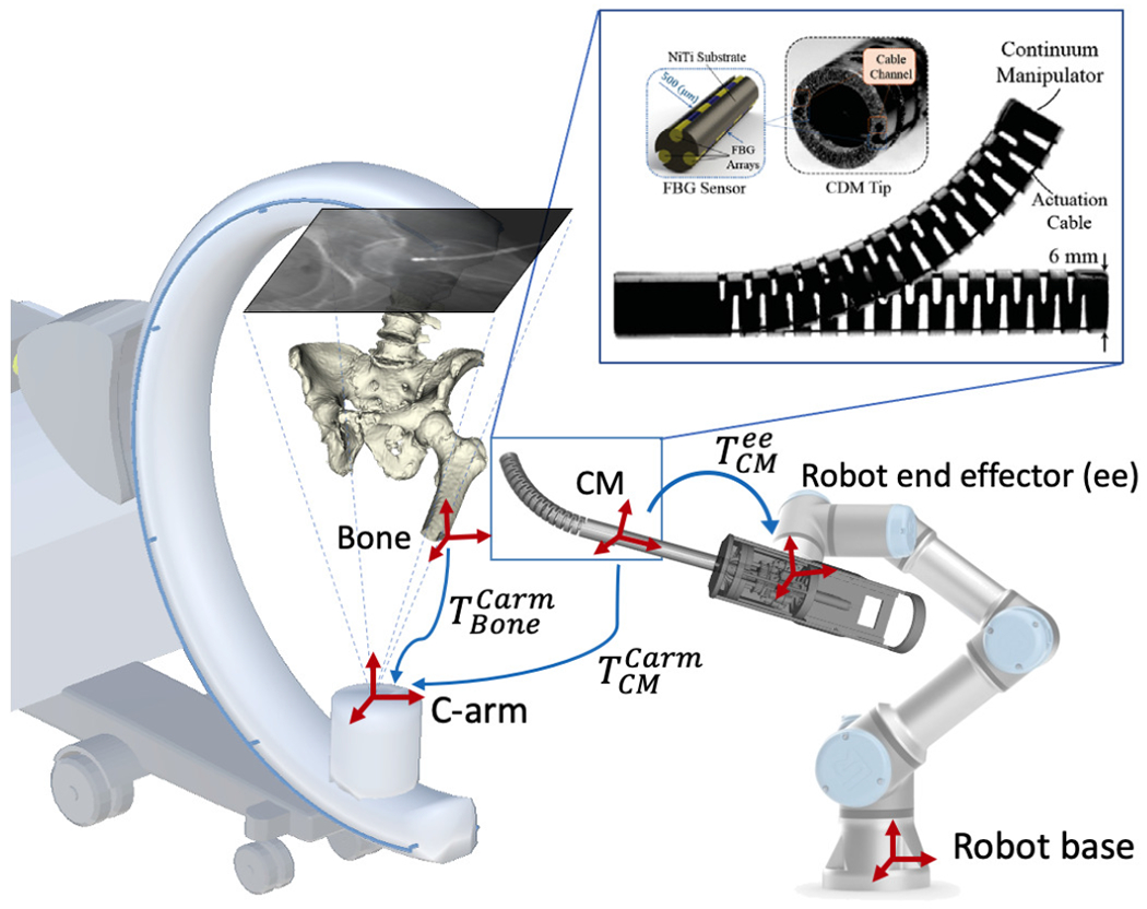
Concept of the proposed fluoroscopic image-based navigation for the CM. Key frames are illustrated as red cross arrows. The blue arrows illustrate the transformations. and are rigid pose estimations of the CM and the bone anatomy in the C-arm coordinate frame. is the hand-eye matrix. Top right: Continuum manipulator and the integrated FBG with triangulation configuration [1].
Otake et al. first applied fluoroscopic image-based 2D/3D registration to estimate the CM pose and shape [23]. However, there were several major limitations: 1) the algorithm was only tested with simulation and camera images instead of real fluoroscopic images; 2) the registration was manually initialized close to the global optima; 3) the method only used a single-view image method, which leads to large ambiguity.
In this paper, we integrate C-arm x-ray image-based navigation into a surgical robotic system with a CM (Fig. 1). The contributions are summarized as follows: 1) learning-based CM detection and localization for CM pose initialization; 2) image-based 2D/3D registration methods for CM shape and pose estimation; 3) a modified hand-eye calibration method that numerically optimizes the hand-eye matrix during the multiple CM 2D/3D registration.
II. Methodology
Fig. 2 presents the overall concepts of the proposed navigation system. It consists of three stages: 1) Pre-operative calibration: The transformation from the CM model reference frame to the rigid-link robot end-effector frame is calibrated using X-ray image-based hand-eye calibration (Fig. 2a). 2) Detection and Initialization: Distinct features of the CM are automatically detected in 2D X-ray images. An initial 3D pose of the CM is estimated using centerline-based 2D/3D registration (Fig. 2b). 3) Registration and Navigation: An accurate 3D pose and shape estimation of the CM is achieved by intensity-based 2D/3D registration using X-ray images and 3D CM model. The pose of the bone anatomy is also estimated using intensity-based 2D/3D registration. The patient is anaesthetized and remains stationary during the pre-operative registration phase. After registration, the rigid-link robot performs navigation, moving the CM according to patient-specific planning (Fig. 2c).
Fig. 2.
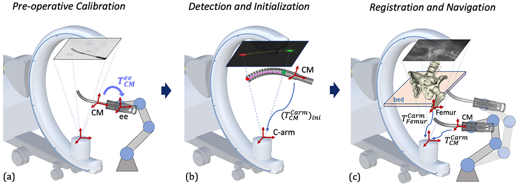
Illustration of the proposed image-based navigation for the CM. Key frames are shown with red cross arrows. (a) Pre-operative hand-eye calibration of the CM. The hand-eye matrix is represented by the curved arrow. (b) CM feature detection and centerline-based initialization. 2D landmark heatmaps and corresponding 3D landmarks are shown in red and green. 2D and 3D centerlines are shown in yellow and pink, respectively. The CM initial pose estimation is marked with a blue arrow. (c) Scheme of 2D/3D registration of the CM and the femur bone anatomy. The registration transformations are described in Section II-C in detail. An example navigation position after registration is illustrated with transparency.
A. CM Model
The CM used in the surgical robotic system is constructed from a hollow superelastic nitinol tube with 27 alternating notches on two sides, using a 4 mm diameter lumen as a flexible instrument channel, with an outside diameter of 6 mm and a total length of 35 mm. It achieves flexibility and compliance in the direction of bending while preserving high stiffness in the perpendicular direction to the bending plane [24], [25], [26]. Two stainless steel cables are embedded through channels on two opposing sides of the CM wall to provide bidirectional planar motion [24], [25]. FBG fibers are integrated into the CM wall channels. The 3D shape of the CM can be inferred in real-time from FBG readings [27], [28].
The CM kinematics configuration is determined by the notch joint angles. Following previous work on kinematic modeling of this CM [23], we assume that the joint angle changes smoothly from one joint to the next. Angles are parameterized as a cubic spline of n equally distributed control points, τi, along the central axis of the CM (n = 5). The model of the CM used in the simulation is built from component volumetric models that are aligned according to the CM kinematic model. The origin of the CM model base reference frame is at the center of the structure between the first notch and the base. The y-z plane defines the CM bending plane and the x axis is perpendicular to the bending plane. Fig. 3 illustrates how the CM model is built and defines the reference frame.
Fig. 3.
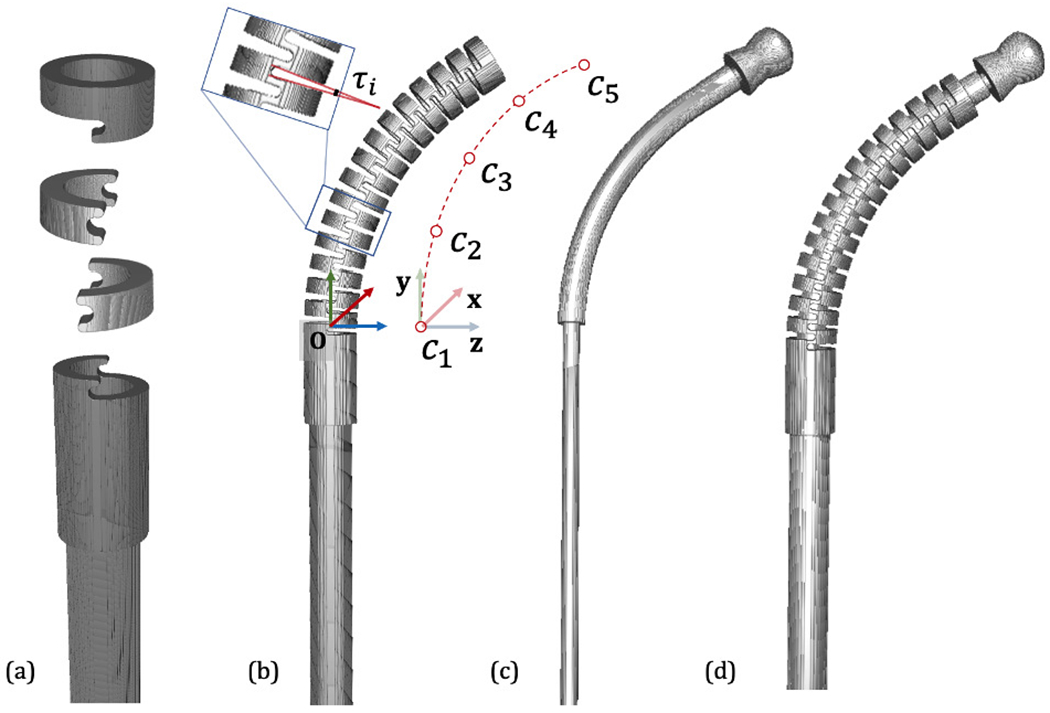
CM Model. (a) Basic model components including base, notch and top segments. (b) An example CM configuration. The notch joint angle is illustrated as τi. The cubic spline control points are shown aside as c1, c2, …, c5. The CM base reference frame is shown in RGB cross arrows. (c) An example flexible tool model. (d) Integrated CM with flexible tool inside.
B. CM Detection and Pose Initialization
The small size, symmetric structure, and dexterity of the CM make it particularly challenging to estimate its pose and shape using a fluoroscopic image. To this end, we propose to exploit semantic prior information on the imaged object, i. e. the CM, to heavily constrain rigid initialization and the deformable registration. We train a convolutional neural network (ConvNet) to segment the CM in X-ray images and simultaneously detect its start and end point using multi-task learning [29], [30], [31], yielding an estimate of the projection domain centerline of the CM. Our segmentation target region covers the 27 alternating notches which discern the CM from other surgical tools (Fig. 4a). The two landmarks are defined as 1) the origin of the CM base reference frame and 2) the center of the distal plane of the last notch, i. e. start and end point of CM centerline (Fig. 4c). Inspired by [32], the 2D centerline is extracted using morphological processing of the segmentation mask (Fig. 4d). Fig. 4 illustrates these features in an example 2D image and 3D model.
Fig. 4.
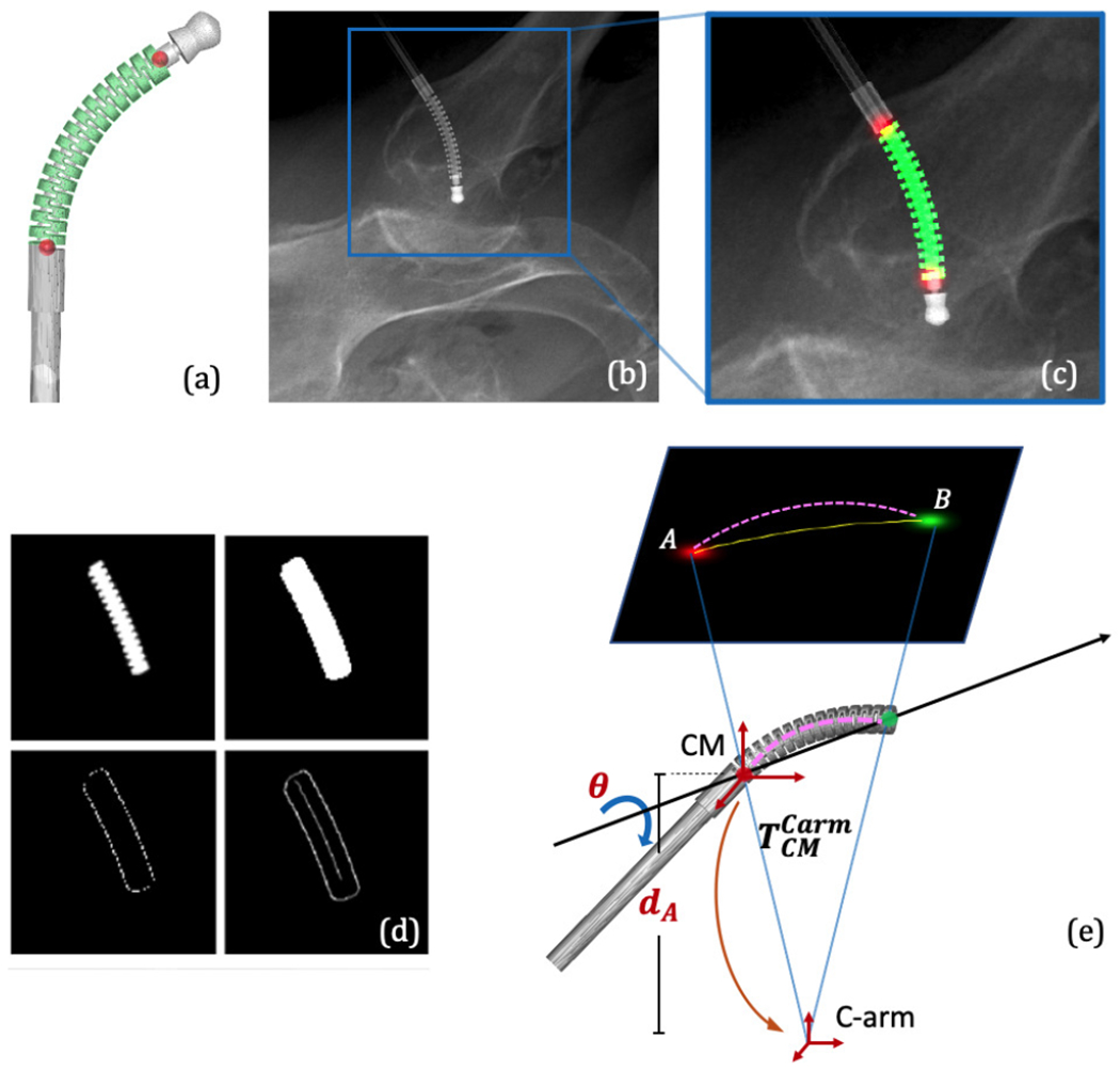
(a) 3D segmentation label and landmark positions on an example CM model. (b) An example simulation image using DeepDRR. (c) Overlay of the 2D segmentation mask and landmark heatmaps on the cropped image in (b). (d) Extraction of the 2D centerline from a segmentation mask consists of dilation, edge and distance map computation, and finally, shortest path extraction. (e) A simplified illustration of the centerline-based 2D/3D registration geometry.
Due to the unavailability of annotated real X-ray images to train ConvNets, we rely on DeepDRR [33], a framework for the physics-based rendering of Digitally Reconstructed Radiographs (DRRs) from 3D CT, to generate simulation images for network training [34]. DeepDRR uses voxel representation, so the CM surface model is voxelized with high resolution to preserve details of the notches. The ConvNet architecture is a U-Net inspired encoder-decoder structure with concurrent segmentation and landmark heatmap network paths [30]. We chose Dice loss to train the segmentation task and the standard l2 loss for the localization task.
The detected semantic features combined with the known C-arm projection geometry and the CM curvature estimation from FBG readings enable an initial 3D pose estimation of the CM using centerline-based 2D/3D registration. Since two 2D landmarks only determine 4 of the required 6 DOF of the CM base rigid transformation, the other two DOFs can be decomposed as the depth distance of the 3D CM base landmark (dA) and the rotation angle (θ) about the axis passing through the two 3D CM landmarks (Fig. 4e). We then perform an optimization search of these two variables (dA, θ) by minimizing the distance between the extracted centerline and the reprojection of the 3D model centerline. Once the global optimal (dA, θ) is found, the rigid CM pose in the C-arm frame can be determined, which is used as the initialization of the intensity-based registration. Since the centerline feature is approximate, we expect to see some ambiguity in depth and rotation which is going to be resolved using intensity-based registration.
C. Image-based 2D/3D Registration
Pose estimation of both the bone anatomy and the CM is achieved using purely image-based 2D/3D registration. Image-based 2D/3D registration of the CM estimates both the rigid pose of the CM relative to the C-arm source frame and the deformable kinematics configuration (τi, i ∈ {1..5}). The initial estimation of is from the centerline-based registration, and the initial τi are from the FBG readings. Our proposed intensity-based registration of the CM is performed by optimizing an image similarity score, combined with a landmark reprojection penalty. DRRs are created by calculating ray casting line integrals through the CM model onto a 2D image plane following the C-arm projection geometry. The similarity score is calculated between each DRR and the intraoperative image I. The landmark reprojection penalty is defined as the sum of l2 distance between each detected landmark position from image I and the projected landmark position from the 3D model.
Given K images (Ik) as input, using J CM model segment volumes (Vj, j ∈ {1..J}, J = 27), a DRR operator (), similarity metric (), and regularizer over plausible poses (), the registration recovers the CM rigid pose and deformation control points (τi) by solving the following optimization problem:
| (1) |
We use patch-based normalized gradient cross correlation (Grad-NCC) as similarity score [35]. The 2D image is first cropped to a 500 × 500 region of interest (ROI) using the two landmark locations and downsampled 4 times in each dimension. The optimization strategy is selected as “Covariance Matrix Adaptation: Evolutionary Search” (CMA-ES) due to its robustness to local minima [36]. The two detected landmarks are incorporated into a reprojection regularizer defined as
| (2) |
The registration produces the rigid pose of the CM in the C-arm frame and the deformation control point values (τi).
Depending on the number of images being used, image-based 2D/3D registration can be classified as single-view (K = 1) or multi-view registration (K > 1). Single-view intensity-based 2D/3D registration suffers from depth ambiguity as 3D features are condensed along the ray-casting line during projection. Since our CM object is deformable and symmetric, it also has the problem of axial rotation ambiguity. Multiple view 2D/3D registration, however, jointly registers several images in which the relative orientation of objects and the imaging device varies, which is effective to remedy the single-view ambiguity [37].
There are two different ways to introduce multiple projection geometries: One is moving the C-arm to multiple views to register a static CM pose, which we phrase as multi-view registration (Fig. 5a). The other one is moving the CM to multiple poses under a single C-arm view, which we phrase as multiple CM registration (Fig. 5b). One key challenge of using multiple images is the relative geometry estimation among these poses, which is essentially a calibration problem. Grupp et al. used the pelvis as a “fiducial” to estimate the multi-view C-arm geometries in the application of osteotomy, and achieved accurate pose estimation of the pelvis fragment with an average fragment pose error of 2.2°/2.2 mm [37]. Thus, we chose to use the pelvis registration to estimate the relative C-arm view geometry for multi-view CM registration.
Fig. 5.
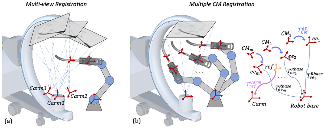
(a): Illustration of multi-view registration. Three example C-arm view source frames are noted with red cross arrows. (b): Illustration of multiple CM registration. The transformations are marked separately on the right and described in Section II-C.
To keep the pelvis as a fiducial and the femur in the field of view, the multiple C-arm view geometries need to be close in rotation, limiting the differences in image appearance. In multiple CM registration, however, the CM poses can be more diverse by moving the rigid-link robot. Relative CM pose geometries can be calculated using the rigid-link robot forward kinematics and the hand-eye matrix . Calibration of the hand-eye matrix is discussed in the following Section II-D.
As shown in Fig. 5b, given M static rigid-link robot forward kinematics and a hand-eye matrix , the CM poses in the static rigid-link robot base frame are with the fact that all configurations share the same hand-eye matrix. We then define a central reference frame with respect to the robot base frame. The reference frame is chosen to be the average position of multiple CM base origins. Its orientation is identity and its translation is the mean translation of all CM poses. The transformation from the reference frame to the C-arm frame is noted as . Each CM pose with respect to the reference frame can be derived by the reference frame definition. We assume the CM shape is fixed during registration. Since the C-arm frame is static, determines all the CM rigid poses in the C-arm frame. Following the formulation of (1), the multiple CM registration can be defined using:
| (3) |
The similarity score, image cropping and downsampling, and optimization strategy are the same as multi-view registration. The landmarks of all CMs are reprojected and incorporated to the regularizer, which can be described as
| (4) |
The registration produces the pose of the reference frame . Each individual pose of the CM in the C-arm frame can be calculated using .
D. Hand-eye Calibration
In order to navigate the CM using the surgical robotic system, the transformation from the CM model frame to the rigid-link robot end effector frame, , needs to be calibrated, which is essentially a hand-eye calibration problem. Fig. 6 illustrates the hand-eye calibration transformations. The conventional hand-eye calibration method collects the calibration data at each individual frame, building matrices A from the robot kinematics and B from sensor readings. If A system of linear equations AX = XB can be defined where X is the hand-eye matrix. However, in this application, X will be inaccurate because B is ambiguous due to severe single-view 2D/3D registration ambiguity. Following the multiple CM registration method as described in Section II-C, we propose a modified hand-eye calibration method that numerically optimizes the hand-eye matrix during the multiple CM registration. Specifically, the hand-eye matrix is now included as a target variable in the optimization problem defined in (3). The intuition is that the collection of multiple calibration CM poses can be regarded as a CM object group, then controls the central pose of the group and controls the relative poses between the CM objects within the group. and are sufficient to determine all the CM rigid poses in the static C-arm frame. The hand-eye calibration can be formulated as
| (5) |
and the regularizer is defined as
| (6) |
Fig. 6.
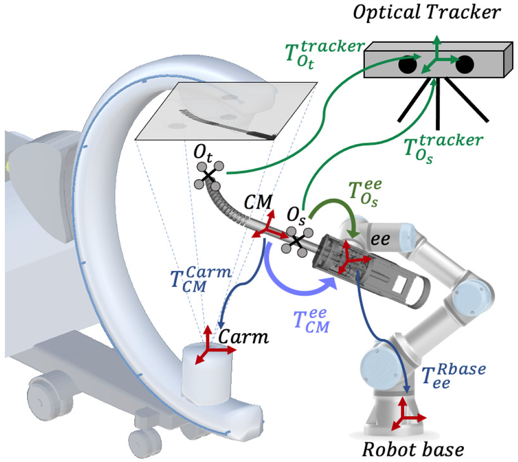
Illustration of the hand-eye calibration transformations. The image-based hand-eye calibration loop is shown in blue. The purple arrow shows the image-based hand-eye transformation . The optical tracker-based hand-eye calibration loop is shown in green, and is the optical tracker-based hand-eye matrix.
The registration directly produces the hand-eye matrix , which integrates the CM model frame to the rigid-link robot end effector frame. There is no need for a fiducial marker in the system as the CM itself is functioning as a fiducial via the model-to-image registration that connects the C-arm camera frame to the robot kinematics.
We move the rigid-link robot to various static configurations within its workspace and the C-arm capture range to collect the calibration data. The C-arm is static during the calibration data collection procedure. At each static configuration, we take an X-ray image of the CM and the rigid-link robot kinematics. The CM curvature is kept constant during the calibration data collection.
In order to validate the accuracy of the hand-eye calibration, we put two rigid bodies with reflective markers on the CM tip segment and shaft. The optical tracker simultaneously tracks these two rigid bodies for validation. At each static configuration, we also take the optical tracker readings. Thus, we can perform an additional standard hand-eye calibration using the accurate optical tracking result. In this case as shown in Fig. 6, the shaft marker pose in the optical tracker frame, , is used to define the A matrix, and the robot kinematics is used to define the B matrix.
E. CM Navigation
Given the registration pose estimation of the femur () and the CM (), the relative transformation of the registration CM frame with respect to the femur anatomy is
| (7) |
Given a target CM pose relative to the femur, , we can calculate a target rigid-link robot forward kinematics using:
| (8) |
where is the rigid-link robot forward kinematics during registration, and is the hand-eye matrix. The CM can be navigated to patient-specific planned positions/trajectories by the rigid-link robot according to the target kinematics.
III. Experiments and Results
We verified our navigation system with a series of simulation studies and cadaveric experiments, including CM detection, 2D/3D registration, hand-eye calibration, and robot navigation. Lower torso CT scan images of a female cadaveric specimen were acquired for fluoroscopic simulation and anatomy registration. The CT voxel spacing is 1.0 × 1.0 × 0.5 mm with dimensions 512 × 512 × 1056. Pelvis and femur volumes were segmented and pelvis anatomical landmarks were annotated using the method described in [13]. We manually annotated a drilling/injection entry point on the greater trochanter surface based on the biomechanical analysis. The simulation environment was set up to approximate a siemens CIOs Fusion C-Arm, which has image dimensions of 1536 × 1536, isotropic pixel spacing of 0.194 mm/pixel, a source-to-detector distance of 1020 mm, and a principal point at the center of the image.
A. CM Detection
Given the CT scan image, we manually defined a rigid transformation such that the CM model was enclosed in the femur, simulating applications in core decompression and fracture repair [11], [38]. Projection using DeepDRR was based on voxel representations of the CT and CM. The CM surface model was voxelized with high resolution to preserve details of the notches. The CM model voxel HU value was set to 2,000 to match measurements from real fluoroscopic acquisition. At positions where the CT volume exhibited overlap with the CM, CT values were ignored to simulate drilling. We used DeepDRR to generate 1) realistic X-ray images, 2) 2D segmentation masks of the CM end-effector, and 3) 2D locations of two key landmarks. 3D CM segmentations and landmark locations were determined by the simulated CM rigid transformation and joint angles, which were then projected to 2D as training labels following the C-arm projection geometry. We generated in total 300 CM models for training and testing. We uniformly sampled the control point values in [−7.9°, 7.9°], source-to-isocenter distance in [400 mm, 500 mm], rotation angle of LAO/RAO in [0°, 360°]; CRAN/CUAD in [75°, 105°], and the volume translation of ±20 mm in x, y and z axis. We included 5 half-body CT scans (512 × 512 × 2590 voxel, 0.853 mm3/voxel) in the experiment. We used 4 CTs for training and the other one for testing. 10,000 images were generated for training and validation with a split of 10:1. 4,000 images were generated for testing. We also tested the performance on 100 real Xray images, where we manually labeled the groundtruth mask and landmarks to compare. These real X-ray images covered three different CM application scenarios: 1) clean background images during hand-eye calibration; 2) the CM above cadaver with soft tissue as background during registration; 3) the CM inserted to a drilled femur. The learning rate was initialized with 0.001 and decayed by 0.1 every 10 epochs.
The segmentation accuracy was calculated using the DICE score of the prediction mask and the groundtruth mask. Landmark detection accuracy was reported with the pixel l2 distance norm. We first tested the network output on the simulation dataset using groundtruth projection. The mean DICE score was 0.993 ± 0.002 and the mean l2 distance error was 0.449 ± 0.525 mm. The mean DICE score on real X-ray was 0.920 ± 0.068 and the mean l2 distance error was 2.62 ± 1.05 mm. Fig. 7 presents the qualitative results. The performance on real data is sufficient to initialize the registration. Thus, we did not consider using the real X-rays to retrain the network for improved accuracy.
Fig. 7.
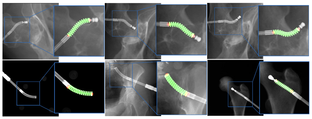
Representative examples of segmentation and landmark detection performance on synthetic and real ex vivo data in the top and bottom rows, respectively. The predicted segmentation mask is shown as green overlay while the estimated landmark locations appear as red blobs.
B. 2D/3D Registration Simulation Study
We tested a series of CM 2D/3D registration workflows, including centerline-based 2D/3D registration, single-view 2D/3D registration, multi-view 2D/3D registration and multiple CM 2D/3D registration. We performed 1,000 simulation studies with randomized geometries for each registration workflow and report the registration accuracy based on our simulated “groundtruth ” poses of the objects and the registration results.
The single-view image is approximately anterior/posterior (AP). Multi-view images included a perturbed AP view and two views at random rotations about the C-arm orbit with a mean and STD of +20 ± 3° and −15 ± 3°. Random movements of the pelvis were sampled uniformly to simulate patient pose variations, including translations from 0 to 10 mm and rotations from −10 to 10 in degrees with respect to a randomly assigned unit vector in pelvis volume center. Rotations of femur were sampled from random rotations with respect to the center of femoral head (FH). The axis of rotation was sampled uniformly between −15 and 15 degrees. The CM was simulated at random positions above the specimen femur head. Perturbed movements of the CM with respect to the C-arm included translations from −30 to 30 mm and rotations from −30 to 30 in degrees with respect to a randomly assigned unit vector in the CM base reference frame (Fig. 8). To test the joint registration of multiple CM poses using a static C-arm view, we randomly sampled four CM poses with constant curvature in the AP view including translations from −10 to 10 mm and rotations between −30 and 30 degrees with respect to randomly assigned unit vector in the CM reference frame for each registration. Fig. 8 shows example simulation images for each registration workflow.
Fig. 8.
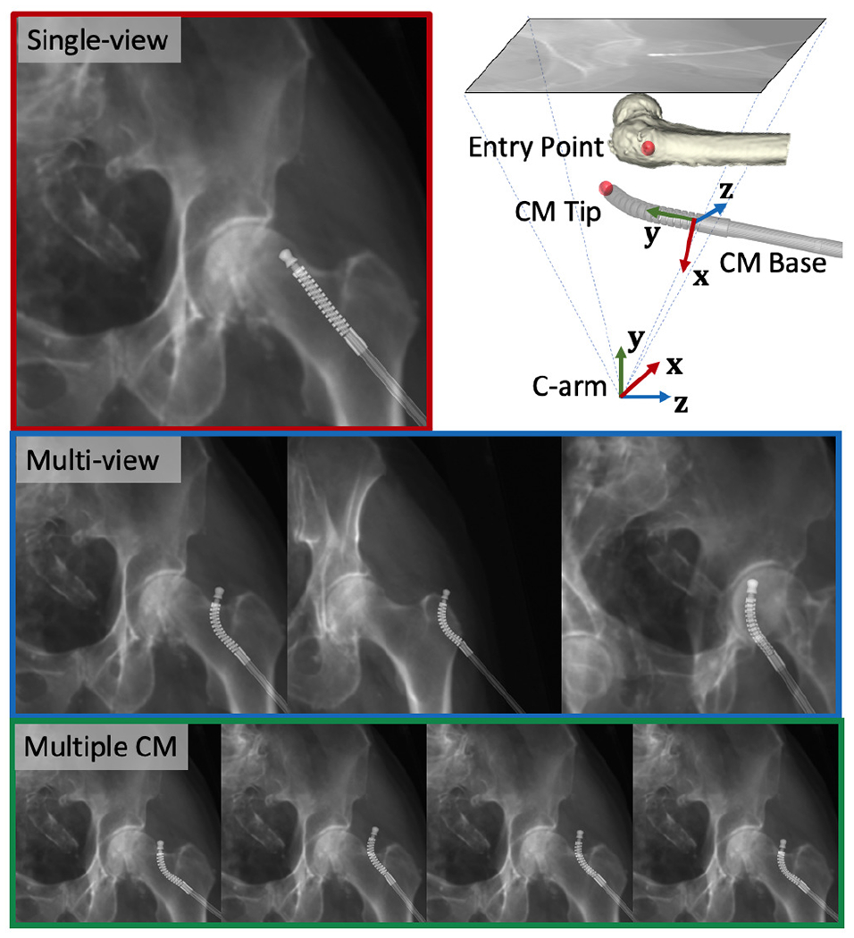
Example of simulation images. Red: single-view image. Blue: multi-view images. Green: Multiple CM pose images. Upper right: CM base and C-arm coordinate frames used to report the registration error are marked with RGB cross arrows using an example projection geometry. The femur entry point and the CM tip point are marked using red spheres.
Registration accuracy was assessed based on the the following metrics: 1) CM tip position in the C-arm frame ; 2) entry point position in the C-arm frame ; relative distance between the CM tip and the entry point in the C-arm frame ; 3) CM base rigid registration transformation in the C-arm frame . We computed the l2 distance error for items 1-3 above compared to the groundtruth point position in the C-arm frame. CM base registration error was reported in the CM base reference frame using . We also computed the CM notch (joint) rotation error compared to groundtruth notch rotation angles. The femur entry point annotation is shown in Fig. 8.
1). Centerline-based Initialization:
We used the CM detection results to test our centerline-based 2D/3D registration algorithm on the AP view simulation images. We assumed the initial curvature readings were added with a uniformly distributed random noise of [−0.5°, 0.5°] to the groundtruth control point values. We uniformly sampled 1,000 points in the search space of dA and θ, and chose the lowest point as global minimum for CM pose estimation. We compared the output with the groundtruth values. dA had a mean error of 29.27 ± 21.02 mm, and θ with 30.78° ± 22.13°.
2). Single-view Registration:
We first performed a single-view pelvis registration and then the femur registration was initialized using the pelvis registration outcome as described in [20]. We used the centerline-based registration result in the above section to initialize the intensity-based 2D/3D registration of the CM. The CM curvature noise model is the same with the centerline-based registration settings. Thus the registration started at a deflected shape estimation and optimized the n + 6 (n = 5) DoF until convergence. We achieved a mean error of 1.17 ± 0.98 mm for the CM tip position and 1.88±1.39 for the relative distance between CM tip and femur bone entry point.
3). Multi-view Registration:
Multiple C-arm pose geometry was estimated using the pelvis registration result of each individual view. The femur registration was initialized by pelvis registration and jointly optimized using multi-view images. The CM registration was initialized using the AP view centerline-based registration result and also jointly optimized with multi-view images. The mean CM tip position error was 0.64 ± 0.45 mm and the mean relative error was 0.62 ± 0.39 mm.
4). Multiple CM Registration:
The femur registration was performed using the same method as in multi-view registration. However, the CM registration was performed using multiple CM pose configurations with the static AP view. We assumed that the relative CM poses were known and the CM curvature was constant among multiple poses. We set the reference frame of multiple CM poses using the method described in Section II-E. The registration optimized the reference frame pose and the CM control points resulting in n+6 (n = 5) DoF until convergence. We achieved a mean CM tip position error of 0.99±0.55 mm and a mean relative error of 1.29 ± 0.78 mm.
Registration errors are presented in Table I. A histogram of the error metrics is shown in Fig. 10. These results are further discussed in the discussion section.
TABLE I.
Simulation Results of Registration Errors
| CM tip (mm) | Bone entry point (mm) | Relative (mm) | CM base translation (mm) | CM base rotation (degrees) | CM notch rotation (degrees) | ||
|---|---|---|---|---|---|---|---|
| Single-view | mean | 1.32 ± 1.21 | 1.65 ± 1.13 | 2.07 ± 1.52 | 1.24 ± 1.05 | 3.32 ± 4.17 | 0.23 ± 0.26 |
| median | 1.04 | 1.33 | 1.73 | 1.03 | 1.68 | 0.16 | |
| Multi-view | mean | 0.54 ± 0.42 | 0.59 ± 0.37 | 0.63 ± 0.39 | 0.52 ± 0.43 | 1.38 ± 1.32 | 0.22 ± 0.23 |
| median | 0.42 | 0.55 | 0.55 | 0.40 | 0.88 | 0.15 | |
| Multiple CM | mean | 0.99 ± 0.59 | 0.63 ± 0.43 | 1.10 ± 0.72 | 1.00 ± 0.60 | 0.14 ± 0.10 | 0.18 ± 0.21 |
| median | 0.94 | 0.51 | 0.95 | 0.95 | 0.12 | 0.12 |
Fig. 10.
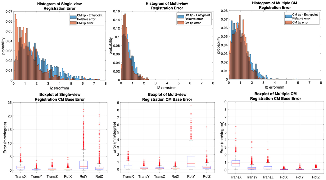
Top: Histogram plot of CM tip error (in orange) and CM tip to femur entry point relative error (in blue) in the AP view C-arm frame. Bottom: Box plot of CM base registration error in translation and rotation of all axes.
C. Hand-eye Calibration
We collected X-ray images using the surgical robotic system for hand-eye calibration. Fig. 9 shows our data collection setup. Two rigid bodies with 4 optical markers each were used for validation. Marker (Os) was fixed rigidly to the shaft of the CM. Marker (Ot) was rigidly attached to the last segment of CM. The two rigid bodies were simultaneously tracked by an NDI Polaris (Northern Digital Inc., Waterloo, Ontario, Canada) system. We used a 6-DOF UR-10 (Universal Robots, Odense, Denmark) as the rigid-link robot. We manually commanded the UR-10 to 60 different configurations. At each configuration, we took an X-ray image using a 30 cm flat panel detector Siemens CIOS Fusion C-Arm, recorded the UR-10 forward kinematics and two polaris marker positions .
Fig. 9.
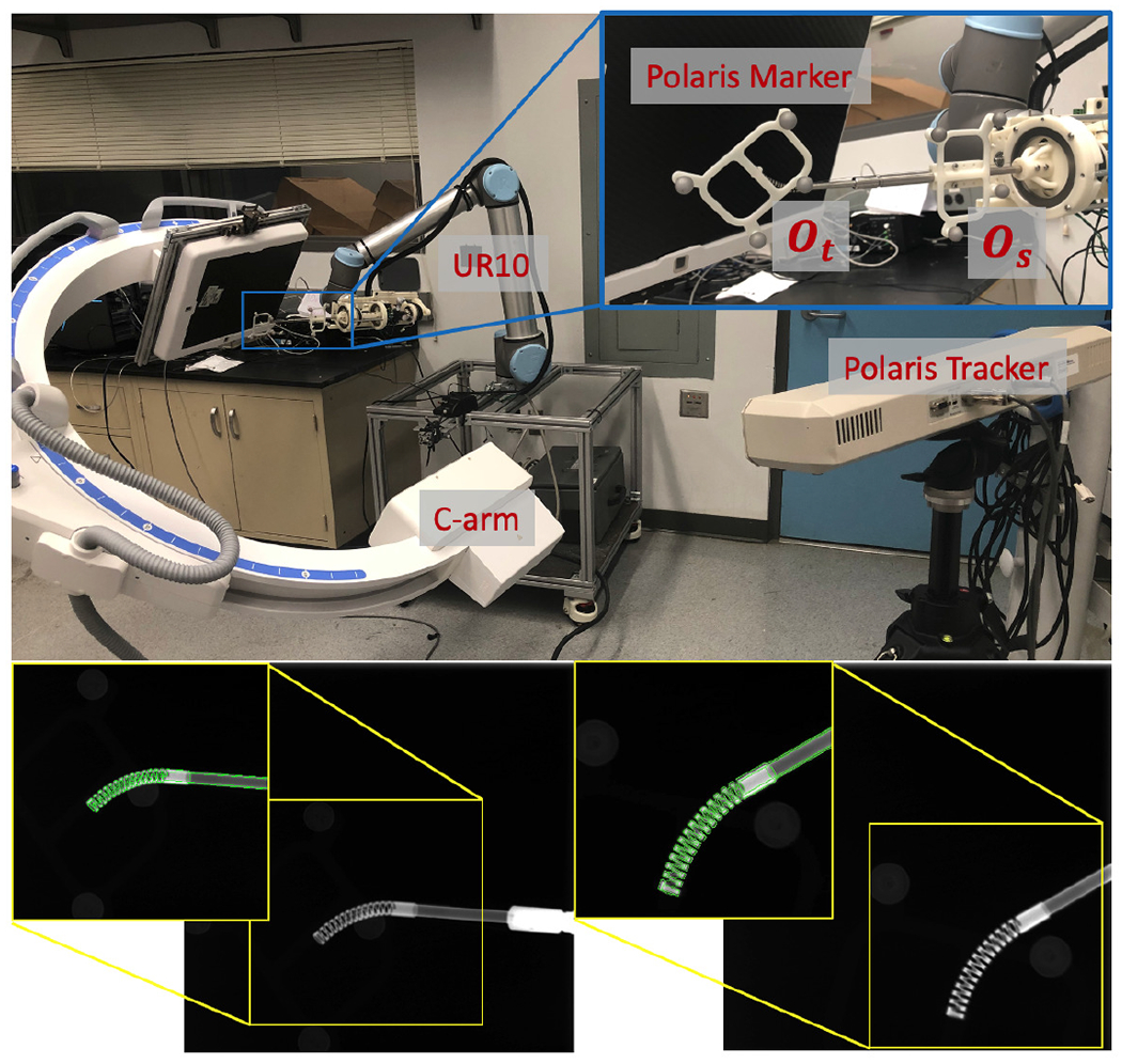
Upper: Hand-eye calibration setup with UR-10, C-arm polaris tracker and markers. Lower: Two example calibration X-ray images. 2D overlay of cropped X-ray (back-ground) and DRR-derived CM edges in green.
We performed the proposed multi-view hand-eye calibration method and found . In order to validate its accuracy, we solved another hand-eye calibration using the optical tracking data of marker (Os). The relative frame transformations and are the A and B matrices of the hand-eye equation AX = Y B, and is the X hand-eye matrix. We then transformed the CM tip position into the robot base frame using both the optical tracking and image-based registration hand-eye results. This can be formulated as:
| (9) |
| (10) |
where pOt is the origin point of the Ot marker and pCMt is the tip point of the CM model. We then computed the l2 distance error between and . We achieved a mean error of 2.15 ± 0.50 mm.
D. Cadaveric Study
We used two cadaveric specimens for our study (Fig. 11). A female Specimen1, including lower torso, pelvis, and femurs, was used for testing registration and robot positioning. A right femur of Specimen2 was used for testing registration when the CM was inserted to the femoral head. To obtain the groundtruth poses for the femur anatomy, metallic BBs were implanted into the femoral head as shown in Fig. 11. For Specimen1, the BBs were implanted closer to the trochanter and the femoral head center region in order to accurately estimate the femoral head pose. For Specimen2, the BBs were evenly distributed around the femoral head. We took CT scans of both Specimen1 and Specimen2. The 3D locations of the BBs were manually labeled in the CT scans of the specimens. The 2D BB locations were manually annotated in the X-ray images.
Fig. 11.
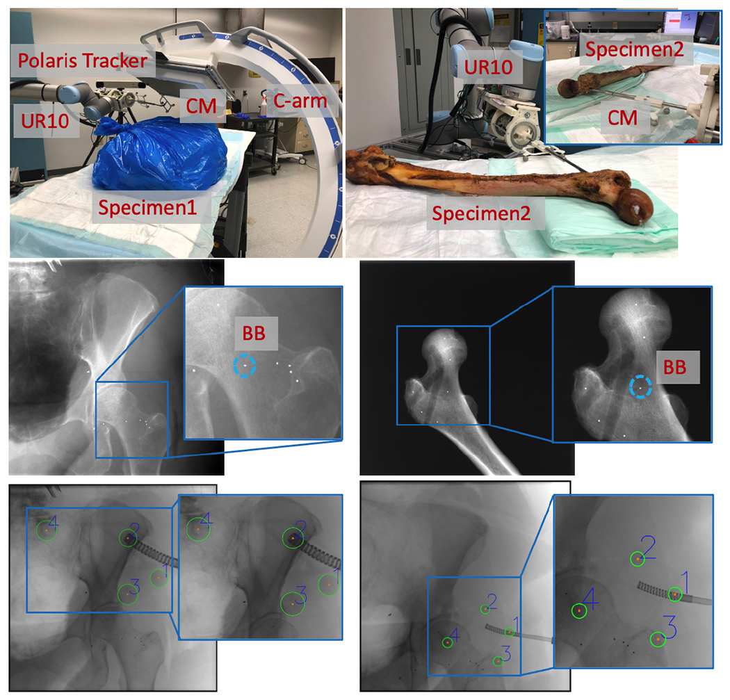
Upper Left: Specimen1 experiment setup with C-arm, UR-10, polaris tracker and CM. Upper Right: Specimen2 experiment setup with UR10 and CM inserted to the femur head. Middle: Examples of BB locations. Bottom: Examples of Polaris fiducial detection results.
We performed the registration workflow five times using Specimen1 with varying C-arm geometries and specimen poses. Each registration workflow had three images for femur registration and four images for CM registration. An example set of images is shown in Fig. 12. After each registration, we commanded the UR-10 to another configuration and took another X-ray image to check the CM reposition accuracy. The optical fiducials were detected in the X-ray image using Hough transform circle detection. The optcial marker (Ot) was attached to the tip segment of the CM. Thus, the groundtruth CM tip position, , in the C-arm frame was calculated by solving the PnP problem using corresponding fiducials in X-ray and marker configurations. The CM tip position error was reported using the l2 distance between estimated tip position from registration and . Groundtruth femur entry point position, , was calculated from the PnP solution using the corresponding BBs. l2 distance between estimated and groundtruth femur entry point was reported as femur entry point error. We also calculated the relative error between the entry point and the CM tip using
| (11) |
Fig. 12.
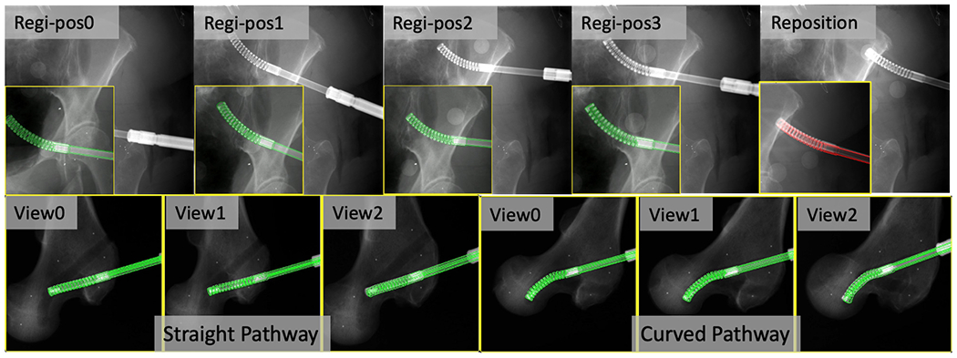
2D overlay examples of fluoroscopic images (background) and DRR-derived edges in green when registration is converged. Top: Cadaveric Specimen1 CM registration results and position overlay after reposition (in red). The original full size image is placed at background and the cropped CM registration image is placed at foreground lower left corner. Bottom: Cadaveric Specimen2 CM registration results of each C-arm view for the straight and curved pathway insertions.
We achieved a mean CM tip position error of 2.86±0.80 mm and a mean relative error between CM tip and femur entry point of 3.17 ± 0.86 mm. Table. II presents the error metrics of each individual trial.
TABLE II.
Cadaver Specimen1 Results of Error Metrics
| Trial ID | I | II | III | IV | V |
|---|---|---|---|---|---|
|
| |||||
| CM Tip Position (mm) | 2.73 | 2.44 | 2.77 | 4.20 | 2.09 |
| Femur Entry Point (mm) | 1.21 | 2.23 | 1.91 | 2.35 | 2.04 |
| Relative (mm) | 2.95 | 3.31 | 3.65 | 4.10 | 1.83 |
For Specimen2, we drilled two pathways inside the femoral head using the CM. One pathway was curved and the other one was straight. The CT scan was taken after the pathways were drilled. Three multiple view X-ray images were taken at several positions along the insertion of the CM into the end of the bone pathways (Fig. 12). We then performed registration of the CM and the femur. We manually annotated both the straight and the curved pathway endpoints in the CT scan. The registration accuracy was reported using the l2 distance between CM tip positions and the CT pathway end points in the CT coordinate frame. We achieved a tip position error of 2.88 mm of the curved pathway registration and 2.65 mm of the straight pathway registration. Fig. 12 illustrates overlay images of the registration convergence stage on Specimen2.
IV. Discussion
Our studies suggest the feasibility of applying purely fluoroscopic image-based registration for the CM navigation. This is of interest because fluoroscopy is the most common imaging modality for orthopedic applications. Our navigation system automates the detection of distinct CM features in fluoroscopic images, which provides an initial CM pose estimation in 3D. Accurate pose estimation is achieved using intensity-based 2D/3D registration of the fluoroscopic image to the CM model. To navigate robotic interventions, the model-based registration result is integrated into the rigid-link robot kinematics configuration using a modified hand-eye calibration method. The proposed navigation system performs single-view or multi-view registrations for both the CM and the bone. Our simulation study shows sub-millimeter accuracy in determining the relative translation error between the CM tip position and the femur entry point. The mean CM base rotation error and the mean CM notch rotation error are less than 0.2 degrees. The cadaver study results suggest a mean translation error of 3.17 mm and a maximum error of 4.10 mm between the two points, which is sufficient for osteonecrosis lesion removal (less than 1 cm), and is feasible to guide the CM for orthopedic applications.
Estimating CM pose and curvature using 2D/3D registration is a challenging problem. Our centerline feature-based registration yields large mean error of 30.78° ± 22.13° in θ (Fig. 4e), because the centerline feature has strong symmetric property which leads to ambiguity when doing rotations. Due to its dexterity, the CM projection image itself has distinct appearance, which is suitable for intensity-based 2D/3D registration. However, the problem of ambiguity along the projection line direction still exists in single-view intensity-based 2D/3D registration, which has large TransX (depth translation) and RotY (axial rotation) errors in simulation studies (Fig. 10).
Multi-view 2D/3D registration, however, combines the information of CM appearance under multiple projection geometries, which fundamentally improves single-view ambiguity. We compared two different methods of introducing multiple views: multi-view registration and multiple CM registration. In simulation, although the mean translation error of multiple CM registration (1.00 mm) is higher than multi-view registration (0.52 mm), the mean axial rotation error is significantly smaller (0.12° compared to 0.88°) and the mean CM notch (joint) rotation error is also smaller (0.18° compared to 0.22°). Thus, multiple CM registration is preferable over multi-view registration for the CM because the rotation accuracy is more important to navigate the positioning robot. Another advantage of the multiple CM registration is that motion of the CM can be automated as opposed to the C-arm motion. Multi-view registration is useful when the CM is inserted inside the bone and cannot move freely (Fig. 12). Multi-view registration can provide an accurate CM tip position estimation with respect to the bone, which is essential for orthopedic applications.
To further demonstrate the relationship between the CM tip error and the registration ambiguity, we create correlation plots of the CM tip position error, , and the CM base origin depth error in the C-arm frame, . All three methods show strong correlation between the CM tip error and the CM base depth error (correlation coefficient > 0.8) (Fig. 13). Single-view registration has the lowest correlation of 0.82, which suggests part of the CM tip error comes from the rotation ambiguity. Multiple CM registration has the highest correlation coefficient of 0.99. This is because the joint registration of multiple CM poses balances the rotational ambiguity of registering a single CM, but the depth ambiguity still arises from using a single view.
Fig. 13.
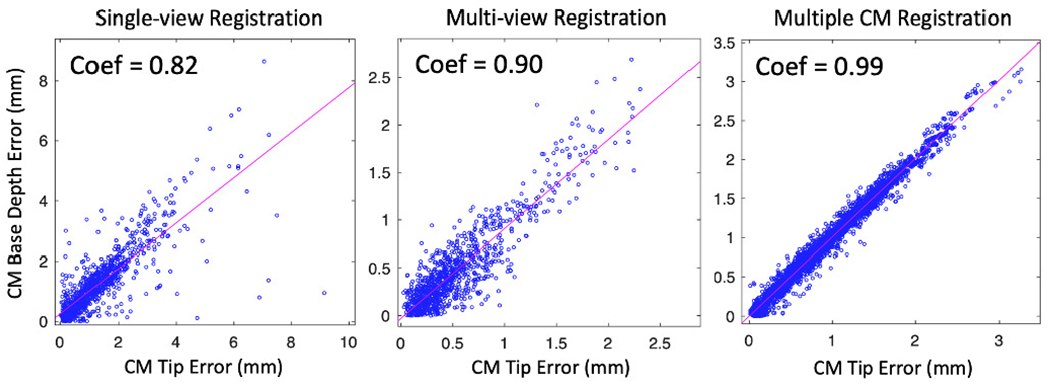
Scatter plots of the correlation matrix between CM tip position error and CM base TransX error of three registration methods. Correlation coefficients are marked on the upper left of each plot.
The accuracy of the cadaveric experiments is less than the simulation study. There are several potential reasons: 1) the CM appearance in real fluoroscopic images is different from simulated DRR images due to spectrum and exposure; 2) the UR kinematics introduces joint configuration errors due to robot going out of calibration; 3) the gravity parameter of the CM and the actuation unit not compensated in the UR kinematics; 4) the BB injection, Polaris fiducial detection, manual annotation and segmentation are likely to introduce errors.
One drawback of the fluoroscopic navigation is the radiation exposure to the patient. Our approach requires six to seven X-rays to register the patient and the CM. This is usually not excessive as compared to other orthopedic applications. However, the pose of patient anatomy can be different after registration due to tool/bone interactions, such as drilling/milling or injection. In this case, additional X-rays are required to correct the registration and update the robot navigation planning. If needed, additional registrations can keep track of the tool pose during surgical operation, which can account for movement of the anatomy, or unmodeled interaction behavior. The process of re-registration will require only 2-3 additional X-ray shots. Unlike other navigation systems which can perform real-time tracking (e.g. optical tracking), fluoroscopic images cannot be acquired at high frequency in real-time for safety reasons. The internal sensing units, like the FBG sensors, can provide real-time CM curvature sensing with high frequency (100 Hz) [1], but the measurements may be inaccurate, and the tool to tissue relationship can not be directly visualized. Thus, to better control the CM, the image-based navigation needs to be combined with the use of internal sensing units.
The feasibility of fusing data from FBG sensors and overhead camera to control the CM motion was previously investigated [39]. The future work includes the study of combining the FBG sensor data with our fluoroscopic image-based registration to perform intra-operative CM control.
V. Conclusion
We present a fluoroscopic navigation system for a surgical robotic system including a continuum manipulator, which automatically detects the CM in fluoroscopic image and uses purely image-based 2D/3D registration to estimate the poses of CM and bone anatomy. The registration is integrated into the robot kinematics to guide CM navigation. Our navigation system was evaluated through intensive simulation and cadaveric specimen studies. The results showed the feasibility to apply the proposed navigation system for CM navigation in robot assisted orthopedic applications. In the future, we will conduct individual calibration experiments to further locate the sources of errors.
VI. Acknowledgement
This research has been finacially supported by NIH R01EB016703, NIH R01EB023939, NIH R21EB020113 and NSF Grant No. DGE-1746891. The funding agency had no role in the study design, data collection, analysis of the data, writing of the manuscript, or the decision to submit the manuscript for publication.
We thank Dr. Liuhong Ma for his help with the cadaveric experiments.
Contributor Information
Cong Gao, Department of Computer Science, Johns Hopkins University, Baltimore, MD, USA 21211.
Henry Phalen, Department of Mechanical Engineering, Johns Hopkins University, Baltimore, MD, USA 21211.
Shahriar Sefati, Department of Mechanical Engineering, Johns Hopkins University, Baltimore, MD, USA 21211.
Justin H. Ma, Department of Mechanical Engineering, Johns Hopkins University, Baltimore, MD, USA 21211
Russell H. Taylor, Department of Computer Science, Johns Hopkins University, Baltimore, MD, USA 21211.
Mathias Unberath, Department of Computer Science, Johns Hopkins University, Baltimore, MD, USA 21211.
Mehran Armand, Department of Mechanical Engineering, Johns Hopkins University, Baltimore, MD, USA 21211; Department of Computer Science, Johns Hopkins University, Baltimore, MD, USA 21211; Department of Orthopaedic Surgery and Johns Hopkins Applied Physics Laboratory, Baltimore, MD, USA 21224.
References
- [1].Sefati S, Hegeman R, Alambeigi F, Iordachita I, and Armand M, “Fbg-based position estimation of highly deformable continuum manipulators: Model-dependent vs. data-driven approaches,” in 2019 International Symposium on Medical Robotics (ISMR). IEEE, 2019, pp. 1–6. [Google Scholar]
- [2].Burgner-Kahrs J, Rucker DC, and Choset H, “Continuum robots for medical applications: A survey,” IEEE Transactions on Robotics, vol. 31, no. 6, pp. 1261–1280, 2015. [Google Scholar]
- [3].Gosline AH, Vasilyev NV, Butler EJ, Folk C, Cohen A, Chen R, Lang N, Del Nido PJ, and Dupont PE, “Percutaneous intracardiac beating-heart surgery using metal mems tissue approximation tools,” The International journal of robotics research, vol. 31, no. 9, pp. 1081–1093, 2012. [DOI] [PMC free article] [PubMed] [Google Scholar]
- [4].Dwyer G, Chadebecq F, Amo MT, Bergeles C, Maneas E, Pawar V, Vander Poorten E, Deprest J, Ourselin S, De Coppi P et al. , “A continuum robot and control interface for surgical assist in fetoscopic interventions,” IEEE robotics and automation letters, vol. 2, no. 3, pp. 1656–1663, 2017. [DOI] [PMC free article] [PubMed] [Google Scholar]
- [5].Wang H, Wang X, Yang W, and Du Z, “Design and kinematic modeling of a notch continuum manipulator for laryngeal surgery,” INTERNATIONAL JOURNAL OF CONTROL AUTOMATION AND SYSTEMS, 2020. [Google Scholar]
- [6].Campisano F, Remirez AA, Landewee CA, Caló S, Obstein KL, Webster RJ III, and Valdastri P, “Teleoperation and contact detection of a waterjet-actuated soft continuum manipulator for low-cost gastroscopy,” IEEE Robotics and Automation Letters, vol. 5, no. 4, pp. 6427–6434, 2020. [DOI] [PMC free article] [PubMed] [Google Scholar]
- [7].Simaan N, Yasin RM, and Wang L, “Medical technologies and challenges of robot-assisted minimally invasive intervention and diagnostics,” Annual Review of Control, Robotics, and Autonomous Systems, vol. 1, pp. 465–490, 2018. [Google Scholar]
- [8].Hwang M and Kwon D-S, “Strong continuum manipulator for flexible endoscopic surgery,” IEEE/ASME Transactions on Mechatronics, vol. 24, no. 5, pp. 2193–2203, 2019. [Google Scholar]
- [9].Ma X, Song C, Chiu PW, and Li Z, “Autonomous flexible endoscope for minimally invasive surgery with enhanced safety,” IEEE Robotics and Automation Letters, vol. 4, no. 3, pp. 2607–2613, 2019. [Google Scholar]
- [10].Johnson AJ, Mont MA, Tsao AK, and Jones LC, “Treatment of femoral head osteonecrosis in the united states: 16-year analysis of the nationwide inpatient sample,” Clinical Orthopaedics and Related Research®, vol. 472, no. 2, pp. 617–623, 2014. [DOI] [PMC free article] [PubMed] [Google Scholar]
- [11].Alambeigi F, Wang Y, Sefati S, Gao C, Murphy RJ, Iordachita I, Taylor RH, Khanuja H, and Armand M, “A curved-drilling approach in core decompression of the femoral head osteonecrosis using a continuum manipulator,” IEEE Robotics and Automation Letters, vol. 2, no. 3, pp. 1480–1487, 2017. [Google Scholar]
- [12].Bakhtiarinejad M, Alambeigi F, Chamani A, Unberath M, Khanuja H, and Armand M, “A biomechanical study on the use of curved drilling technique for treatment of osteonecrosis of femoral head,” in Computational Biomechanics for Medicine. Springer, 2020, pp. 87–97. [Google Scholar]
- [13].Gao C, Farvardin A, Grupp RB, Bakhtiarinejad M, Ma L, Thies M, Unberath M, Taylor RH, and Armand M, “Fiducial-free 2d/3d registration for robot-assisted femoroplasty,” IEEE Transactions on Medical Robotics and Bionics, vol. 2, no. 3, pp. 437–446, 2020. [DOI] [PMC free article] [PubMed] [Google Scholar]
- [14].Otake Y, Armand M, Sadowsky O, Armiger RS, Kutzer MD, Mears SC, Kazanzides P, and Taylor RH, “An image-guided femoroplasty system: development and initial cadaver studies,” in Medical Imaging 2010: Visualization, Image-Guided Procedures, and Modeling, vol. 7625. International Society for Optics and Photonics, 2010, p. 76250P. [Google Scholar]
- [15].de Preux M, Klopfenstein Bregger MD, Brünisholz HP, Van der Vekens E, Schweizer-Gorgas D, and Koch C, “Clinical use of computer-assisted orthopedic surgery in horses,” Veterinary Surgery, vol. 49, no. 6, pp. 1075–1087, 2020. [DOI] [PubMed] [Google Scholar]
- [16].Sefati S, Hegeman R, Alambeigi F, Iordachita I, Kazanzides P, Khanuja H, Taylor R, and Armand M, “A surgical robotic system for treatment of pelvic osteolysis using an fbg-equipped continuum manipulator and flexible instruments,” IEEE/ASME Transactions on Mechatronics, 2020. [DOI] [PMC free article] [PubMed] [Google Scholar]
- [17].Ganji Y, Janabi-Sharifi F, and Cheema AN, “Robot-assisted catheter manipulation for intracardiac navigation,” International journal of computer assisted radiology and surgery, vol. 4, no. 4, pp. 307–315, 2009. [DOI] [PubMed] [Google Scholar]
- [18].Loser MH and Navab N, “A new robotic system for visually controlled percutaneous interventions under ct fluoroscopy,” in International Conference on Medical Image Computing and Computer-Assisted Intervention. Springer, 2000, pp. 887–896. [Google Scholar]
- [19].Zixiang W, Hongxun S, Zhou Y, and Zhang H, “Robot-assisted orthopedic surgery,” in Digital Orthopedics. Springer, 2018, pp. 425–447. [Google Scholar]
- [20].Gao C, Grupp RB, Unberath M, Taylor RH, and Armand M, “Fiducial-free 2d/3d registration of the proximal femur for robot-assisted femoroplasty,” in Medical Imaging 2020: Image-Guided Procedures, Robotic Interventions, and Modeling, vol. 11315. International Society for Optics and Photonics, 2020, p. 113151C. [Google Scholar]
- [21].Mishra V, Singh N, Tiwari U, and Kapur P, “Fiber grating sensors in medicine: Current and emerging applications,” Sensors and Actuators A: Physical, vol. 167, no. 2, pp. 279–290, 2011. [Google Scholar]
- [22].Sefati S, Sefati S, Iordachita I, Taylor RH, and Armand M, “Learning to detect collisions for continuum manipulators without a prior model,” in International Conference on Medical Image Computing and Computer-Assisted Intervention. Springer, 2019, pp. 182–190. [Google Scholar]
- [23].Otake Y, Murphy RJ, Kutzer M, Taylor RH, and Armand M, “Piecewise-rigid 2d-3d registration for pose estimation of snake-like manipulator using an intraoperative x-ray projection,” in Medical Imaging 2014: Image-Guided Procedures, Robotic Interventions, and Modeling, vol. 9036. International Society for Optics and Photonics, 2014, p. 90360Q. [Google Scholar]
- [24].Kutzer MD, Segreti SM, Brown CY, Armand M, Taylor RH, and Mears SC, “Design of a new cable-driven manipulator with a large open lumen: Preliminary applications in the minimally-invasive removal of osteolysis,” in 2011 IEEE International Conference on Robotics and Automation. IEEE, 2011, pp. 2913–2920. [Google Scholar]
- [25].Murphy RJ, Kutzer MD, Segreti SM, Lucas BC, and Armand M, “Design and kinematic characterization of a surgical manipulator with a focus on treating osteolysis,” Robotica, vol. 32, no. 6, p. 835, 2014. [Google Scholar]
- [26].Armand M, Kutzer MD, Brown CY, Taylor RH, and Basafa E, “Cable-driven morphable manipulator,” Aug. 22 2017, uS Patent 9,737,687.
- [27].Sefati S, Alambeigi F, Iordachita I, Armand M, and Murphy RJ, “Fbg-based large deflection shape sensing of a continuum manipulator: Manufacturing optimization,” in 2016 IEEE SENSORS. IEEE, 2016, pp. 1–3. [Google Scholar]
- [28].Sefati S, Gao C, Iordachita I, Taylor RH, and Armand M, “Data-driven shape sensing of a surgical continuum manipulator using an uncalibrated fiber bragg grating sensor,” IEEE Sensors Journal, 2020. [DOI] [PMC free article] [PubMed] [Google Scholar]
- [29].Laina I, Rieke N, Rupprecht C, Vizcaíno JP, Eslami A, Tombari F, and Navab N, “Concurrent segmentation and localization for tracking of surgical instruments,” in International conference on medical image computing and computer-assisted intervention. Springer, 2017, pp. 664–672. [Google Scholar]
- [30].Gao C, Unberath M, Taylor R, and Armand M, “Localizing dexterous surgical tools in x-ray for image-based navigation,” arXiv preprint arXiv:1901.06672, 2019. [Google Scholar]
- [31].Grupp RB, Unberath M, Gao C, Hegeman RA, Murphy RJ, Alexander CP, Otake Y, McArthur BA, Armand M, and Taylor RH, “Automatic annotation of hip anatomy in fluoroscopy for robust and efficient 2d/3d registration,” International Journal of Computer Assisted Radiology and Surgery, pp. 1–11, 2020. [DOI] [PMC free article] [PubMed] [Google Scholar]
- [32].Unberath M, Taubmann O, Hell M, Achenbach S, and Maier A, “Symmetry, outliers, and geodesics in coronary artery centerline reconstruction from rotational angiography,” Medical physics, vol. 44, no. 11, pp. 5672–5685, 2017. [DOI] [PubMed] [Google Scholar]
- [33].Unberath M, Zaech J-N, Lee SC, Bier B, Fotouhi J, Armand M, and Navab N, “Deepdrr—a catalyst for machine learning in fluoroscopy-guided procedures,” in International Conference on Medical Image Computing and Computer-Assisted Intervention. Springer, 2018, pp. 98–106. [Google Scholar]
- [34].Unberath M, Zaech J-N, Gao C, Bier B, Goldmann F, Lee SC, Fotouhi J, Taylor R, Armand M, and Navab N, “Enabling machine learning in x-ray-based procedures via realistic simulation of image formation,” International journal of computer assisted radiology and surgery, vol. 14, no. 9, pp. 1517–1528, 2019. [DOI] [PMC free article] [PubMed] [Google Scholar]
- [35].Grupp RB, Armand M, and Taylor RH, “Patch-based image similarity for intraoperative 2d/3d pelvis registration during periacetabular osteotomy,” in OR 2.0 Context-Aware Operating Theaters, Computer Assisted Robotic Endoscopy, Clinical Image-Based Procedures, and Skin Image Analysis. Springer, 2018, pp. 153–163. [Google Scholar]
- [36].Hansen N and Ostermeier A, “Completely derandomized self-adaptation in evolution strategies,” Evolutionary computation, vol. 9, no. 2, pp. 159–195, 2001. [DOI] [PubMed] [Google Scholar]
- [37].Grupp RB, Hegeman RA, Murphy RJ, Alexander CP, Otake Y, McArthur BA, Armand M, and Taylor RH, “Pose estimation of periacetabular osteotomy fragments with intraoperative x-ray navigation,” IEEE Transactions on Biomedical Engineering, vol. 67, no. 2, pp. 441–452, 2019. [DOI] [PMC free article] [PubMed] [Google Scholar]
- [38].Alambeigi F, Bakhtiarinejad M, Azizi A, Hegeman R, Iordachita I, Khanuja H, and Armand M, “Inroads toward robot-assisted internal fixation of bone fractures using a bendable medical screw and the curved drilling technique,” in 2018 7th IEEE International Conference on Biomedical Robotics and Biomechatronics (Biorob). IEEE, 2018, pp. 595–600. [DOI] [PMC free article] [PubMed] [Google Scholar]
- [39].Alambeigi F, Pedram SA, Speyer JL, Rosen J, Iordachita I, Taylor RH, and Armand M, “Scade: Simultaneous sensor calibration and deformation estimation of fbg-equipped unmodeled continuum manipulators,” IEEE Transactions on Robotics, vol. 36, no. 1, pp. 222–239, 2019. [DOI] [PMC free article] [PubMed] [Google Scholar]


