Abstract
Objective:
To determine the effect of labiolingual inclination of a maxillary central incisor on the magnitude and distribution of stresses within the periodontal space.
Materials and Methods:
Five three-dimensional finite element models of a right maxillary central incisor were created with 0°, 10°, 20°, 30°, and 40° inclination. Each incisor model was subjected to a 1 N lingual-directed force and 6–12 N·mm countertipping moment on the labial surface. The stress level within the periodontal ligament was calculated in terms of maximum principal stresses.
Results:
With increased inclination, compressive stresses tended to increase whereas tensile stresses tended to decrease. The location where compressive stress was prevalent changed from the midroot area to the apical area on the lingual side, while the area where tensile stresses were predominant changed from the midroot area to the cervical area on the labial side.
Conclusion:
There are more compressive stresses concentrated at the apex of incisors with a high degree of inclination than in incisors that are more upright. This may be associated with the higher clinical incidence of apical root resorption found in inclined maxillary central incisors.
Keywords: Inclination, Principal stress, Finite element analysis, Periodontal ligament, Orthodontics
INTRODUCTION
Stress-strain distribution within the periodontal ligament (PDL), resulting from orthodontic loading, is an initiating factor for orthodontic tooth movement. Excessive periodontal stress is a major cause for external apical root resorption (EARR).1,2 EARR incidences due to orthodontic tooth movement are most common in maxillary incisors.1,3–5
Many studies have investigated periodontal stresses caused by orthodontic loading. These stresses are often determined with finite element analysis (FEA). FEA is an engineering tool for calculating stresses and strains within complex structures and has been widely adopted in biomedical research. The principle of FEA is based on dividing a complex structure into small, simple sections, called elements. These elements are given properties (such as the Young's modulus) to account for their physical response to an external load (such as orthodontic forces) or displacement (such as bending). All individual physical elements are bound together by nodes, forming a cohesive mesh. Using computer-solved numerical algorithms, the stress-strain response to a load can be calculated within each element.6,7
Studies that analyzed stresses in the PDL with FEA suggest that tipping movement causes higher-stress concentrations at the cervical area than in the apical area.7–12 Other studies reported that bodily movement concentrates stresses at the midroot area with an almost uniform distribution and that the stress level from bodily movement is lower than that from the tipping movement.11–14 However, clinically maxillary central incisors have the highest incidence of root resorption in the apical area,1,3–5 suggesting that PDL stresses should be the highest in the apical region.
The finite element studies that found higher stresses in other areas than the apical region were conducted for teeth in an upright position, with the forces applied perpendicular to the occlusal plane. Clinically, however, upper central incisors are approximately 30° inclined to the line perpendicular to the occlusal plane.15,16 Moreover, the force vector is rarely perpendicular to the long axis of an incisor. The purpose of this study was therefore to determine the effect of labiolingual inclination on the magnitude and distribution of stresses within the PDL for a maxillary central incisor.
MATERIALS AND METHODS
Stresses in the PDL were investigated using FEA (Marc/Mentat, MSC Software Corporation, Santa Ana, Calif). Finite element models consist of (1) geometry, (2) mechanical properties of materials involved, and (3) applied loading and constraints.
Five three-dimensional geometrical models were created, representing a right maxillary central incisor. The long axis of each incisor model was 0°, 10°, 20°, 30°, or 40° inclined to the line perpendicular to the occlusal plane. Each of the five models consisted of an incisor, PDL, and a section of alveolar bone. Each model was subdivided into 2400 eight-node isoparametric hexahedral solid elements and 2896 nodes (Figure 1).
Figure 1.
Dimensions of the three-dimensional finite element model of a right maxillary central incisor, shown in midsagittal view. The model consisted of the incisor, periodontal ligament (PDL), and surrounding bone. Five inclinations were simulated: 0°, 10°, 20°, 30°, and 40°.
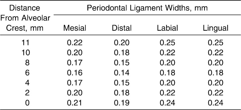
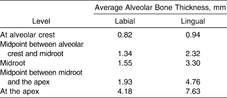
The incisor geometry was based on average anatomical dimensions from Wheeler's Dental Anatomy textbook.17 Tooth length, measured from incisal edge to root apex, was 23.5 mm; the crown was 10.5 mm and the root 13 mm. The mesiodistal width of the crown was 8 mm and the labiolingual width 7 mm. The width of the PDL was adjusted at different cervicoapical levels according to data from Coolidge (Table 1).18 The PDL covered 11 mm of the root surface, measured from the apex. Average alveolar bone thickness at five height levels on the labial and lingual sides was determined from 30 cephalometric radiographs (Table 2) and applied in the models. Cervical height of alveolar bone was the same level as the height of the PDL. The base of the model was 4-mm thick, measured from the apical PDL.
Table 1.
The Geometry of the Periodontal Ligament Widths18
Table 2.
Average Alveolar Bone Thickness at Five Levels
Material properties were assigned to the elements. All materials were assumed to be homogeneous, isotropic, and linear-elastic. Table 3 lists the applied properties for the tooth, PDL, and alveolar bone. These values were compiled from published data.8,11,13,19–24
Table 3.
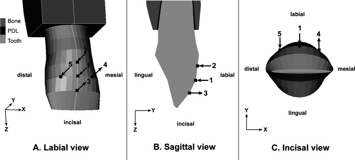
Each of the five inclination models was subjected to three loads on the crown (Figure 2):
Figure 2.
(A) Labial aspect of incisor, showing locations of the applied forces and moments. Arrow 1 is a lingual-directed force (F) of 1 N. Arrows 2 and 3 represent the countertipping moment (Mt) that produces labial crown movement. Arrows 4 and 5 represent the counter-rotation moment (Mr) that produces distolingual rotation. (B) Sagittal aspect of crown, showing the lingual-directed force and Mt. (C) Incisal aspect, showing the lingual-directed force and Mr.
Lingual-directed force (F) of 1 N, placed at the midpoint of mesiodistal width, 4.5 mm apical to the incisal edge, parallel to the occlusal plane. This load did not change with inclination.
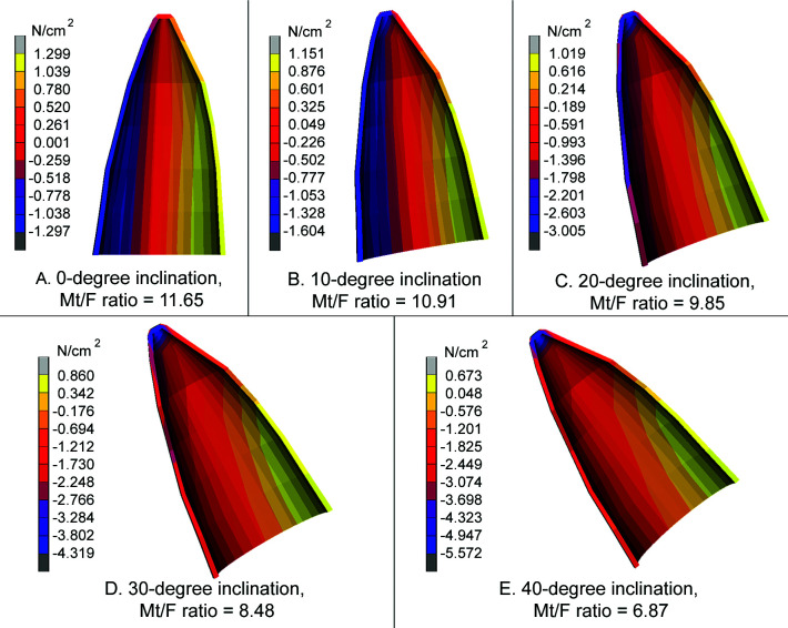
Countertipping moment (Mt) caused labial crown movement. The Mt magnitude generating Mt/F ratios, which varied from 6 to 12, and ratios that created bodily movement were applied. These ratios were 11.65, 10.91, 9.85, 8.48, and 6.87 for the 0°, 10°, 20°, 30°, and 40° inclination, respectively.25 Bodily movement happened when nodes at the center of the incisal edge and apex moved the same distance in the same direction.
Counter-rotation moment (Mr) that resulted in distolingual rotation counteracted the confounding moment. Mr was calibrated to make the mesial and distal ends of the incisal edge move an equal distance in the same direction. The horizontal distance of this couple was 4.87 mm.
Free body motion for the model was constrained by fixing all nodes at the base of the model (bone) in all directions. Nodes on mesial and distal surfaces of the bone section were fixed only in mesiodistal and incisoapical directions, which allowed bending of the bone in labiolingual directions.21
The stress level within the PDL was calculated in terms of principal stresses. Principal stresses are independent of the orientation of the coordinate system and represent the highest normal stress components. In a three-dimensional stress field, there are three principal stress components, ranked in descending order. From all principal stresses calculated in the entire PDL, the maximum value of the first principal stress and the minimum value of the third principal stress were recorded for each model and each Mt/F ratio. In this study, these were named the maximum principal stress and the minimum principal stress, respectively.
RESULTS
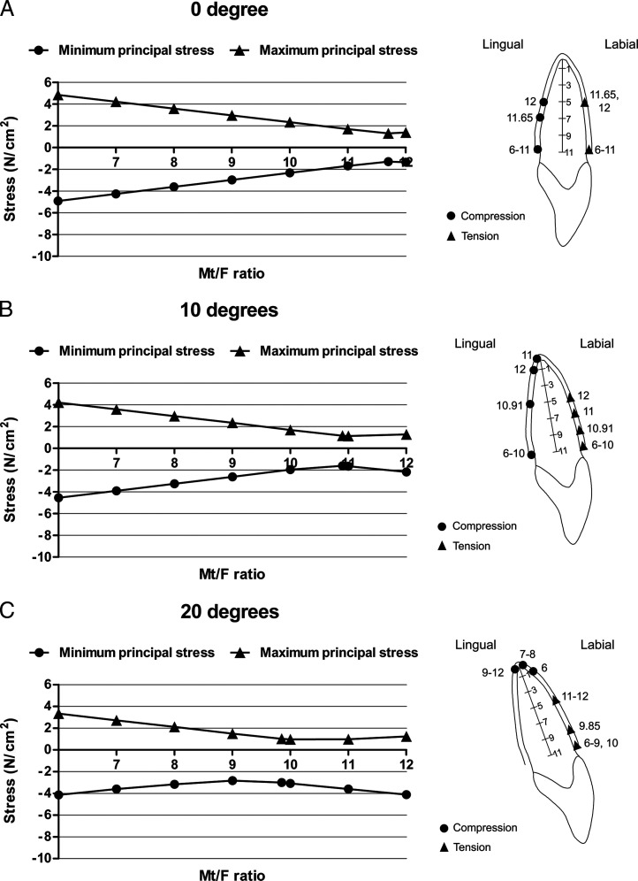
For each inclination, the relationships between the Mt/F ratio and the maximum and minimum principal stresses are plotted in Figure 3. The locations of the principal stresses extremes in the PDL for each Mt/F ratio and for the Mt/F ratio that produced bodily movement are shown in an accompanying midsagittal view. It was found that all values of the minimum principal stress in the PDL were negative, so they could be called maximum compressive stress. All values of the maximum principal stress were positive, so they were called maximum tensile stress. The lowest magnitudes of the maximum compressive and tensile stress at each inclination are summarized in Table 4.
Figure 3.
Relationships between the countertipping moment/lingual-directed force (Mt/F ratio) and principal stress for 0°, 10°, 20°, 30°, or 40° tooth inclination. Diagrams on the right show locations of maximum compressive and tensile stress. (A) 0° inclination, (B) 10° inclination, (C) 20° inclination, (D) 30° inclination, (E) 40° inclination.
Table 4.
The Lowest Magnitude of Maximum Compressive and Tensile Stress (N/cm2) at Each Inclination
At 0° inclination, the lowest magnitude of both maximum compressive and tensile stress occurred at midroot on lingual and labial sides, respectively, when the Mt/F ratio was the ratio that produced bodily movement (11.65). When the Mt/F ratio decreased, both the maximum compressive and tensile stress concentrations moved to the cervical area on the lingual and labial sides, respectively (Figure 3A).
When the inclination increased to 10°, the lowest magnitude of maximum compressive and tensile stress still occurred close to the Mt/F ratio that produced bodily movement (10.91) and also occurred at midroot. When the Mt/F ratio decreased, maximum compressive and tensile stress appeared at the cervical area on the lingual and labial sides, respectively. Conversely, at an Mt/F ratio of 12, maximum compressive stress was produced at the apex on the lingual side, whereas maximum tensile stress was at the labial midroot area (Figure 3B).
For the 20° inclination model, the maximum compressive stress occurred in the apical region for all Mt/F ratios, while maximum tensile stress occurred on the labial side, moving from cervical to the midroot with increasing Mt/F ratios (Figure 3C).
In the normal and proclination models (30° and 40°), the lowest magnitude of the maximum compressive stress still occurred at Mt/F ratios (6) close to the ratios that produced bodily movement (6.87). However, for the maximum tensile stresses, the lowest values were found for higher Mt/F ratios (8). All Mt/F ratios produced their maximum compressive stress at the apex on the lingual side. Maximum tensile stresses were found at the labial side; increasing Mt/F ratios moved the maximum tensile stress location from the cervical to apical region (Figure 3D,E).
Figure 3.
Continued.
For each inclination and Mt/F ratio that produced bodily movement, the magnitude and location of the maximum compressive and tensile stress are summarized in Table 5, while Figure 4 shows their stress distribution patterns according to a linear color scale (positive is tensile, negative is compressive). The major principal stress in Figure 4 is the maximum principal stress component with the highest absolute value. The table and figure show that with increasing inclination, compressive stresses that dominate in the lingual area move from the midroot to the apical region while increasing in magnitude. Meanwhile, tensile stresses dominate in the labial area and move from the midroot toward the cervical area while decreasing in magnitude.
Table 5.
Maximum Compressive and Tensile Stress (N/cm2) for the Countertipping/Lingual-Directed Force Ratio (Mt/F) That Produced Bodily Movement at Each Inclination
Figure 4.
Stress distributions (major principal stresses) when Mt/F was the ratio that produced bodily movement. Note the differences in stress ranges.
DISCUSSION
Most finite element studies that investigated stress distributions due to orthodontic forces modeled teeth in the upright position and applied forces perpendicular to the occlusal plane.7–12,26 Since central incisors have an approximately 30° inclination and orthodontic forces are usually also angled with respect to the occlusal plane, this study evaluated how inclination affects the stresses.
First, the current results for an upright incisor were compared with previous studies to validate the analysis. For the 0° inclination model, when controlled tipping movement was simulated (Mt/F ratio < 11.65), this study found that both maximum compressive and tensile stress occurred at the cervical part of the PDL. This corresponds with previous studies.8,10 During bodily movement (Mt/F ratio = 11.65), stress in the PDL was almost uniform along the root surface. Maximum compressive and tensile stress occurred at midroot areas on the lingual and labial sides, respectively. This is also confirmed by previous publications.13 Bodily movement produced the lowest magnitudes of the compressive and tensile stress compared with controlled tipping and root movement. These magnitudes were 1.297 and 1.299 N/cm2 (129.7 and 129.9 g/cm2), respectively (Table 5). The classic concept of the optimal force proposed by Schwarz27 states that optimal force should approximate the capillary vessels' blood pressure, which is 20–26 g/cm2. Bioprogressive therapy by Ricketts et al.28 suggested an optimal force of 100 g/cm2, whereas Lee29 reported 197 g/cm2 as optimal for tooth movement. While there is thus no consensus about the precise value for the optimal stress level, our stress magnitudes were within the range of reported values.
When the incisor was modeled at increasing inclination, a controlled tipping movement resulted in the maximum compressive stress to migrate to the apex, while the maximum tensile stress was in the cervical area. The finding about the compressive stress corresponds with the study of Field et al.,30 but the response of the tensile stress is different. They found that both compressive and tensile stress coincided with the apical site. The occurrence of the maximum compressive stress in the apical area and the maximum tensile stress in the cervical area for the inclined incisor may be explained by the force direction. Inclination results in an increased intrusive force component parallel to the long axis that thus creates increased compressive stress conditions at the apex and also tension in the PDL in the longitudinal direction. Meanwhile, the perpendicular component that caused the high tension in the cervical area for the 0° inclination model decreases. For bodily movement, when inclination increased, the location of the maximum compressive stress not only moved to the apical area but also increased in magnitude. This observation correlates with root resorption observations in clinical practice and studies. Maxillary central incisors have been reported to be the most vulnerable for root resorption after orthodontic treatment.1,3–5 Taner et al.31 reported that Class II division 1 subjects with more improved incisor inclination had higher root resorption than Class I subjects, following extraction therapy. Weiland32 found resorption lacunae distributed mainly around compression areas. Many studies have confirmed that increased inclination and overjet is a risk factor for root resorption.4,5,33
The results of this study generally correlated well with clinical observations and other studies, despite the various assumptions and simplifications that were required in the analysis. In reality, PDL properties are nonlinear and anisotropic,34,35 but because their precise response is still not well defined, this study assumed homogeneous, isotropic, and linear-elastic properties. This simplified PDL response should still provide useful general insight because displacements were relatively small. To ensure that a specific elastic modulus choice would not predetermine the general conclusions, a range of modulus values was tested as part of the preparation for this analysis. Anatomy also plays a significant role in distribution of stresses. The maxillary central incisor geometry was established for average anatomical dimensions. The results of this analysis are thus not for one specific clinical case but apply to an average among individuals.21,23 Therefore, our findings can show how inclination may generally affect the mechanical response of teeth. Future studies could further refine the loading and approximations of material properties to further improve our understanding of stresses within the PDL.
CONCLUSIONS
With increased inclination, compressive stress tends to increase, whereas tensile stress tends to decrease.
For low degrees of inclination, both compressive and tensile stress distribution are uniformly distributed along the lingual and labial root surface, respectively. For high degrees of inclination, compressive stress dominates at the root apex, while the highest tensile stresses are found along the root surface on the labial side.
With bodily movement and increased inclination, the area of maximum compressive stress changes from midroot to the apical area and increases in magnitude. The area of maximum tensile stress changes from midroot to the cervical area and decreases in magnitude.
Acknowledgment
The authors express their deep appreciation to the Chulalongkorn University Centenary Academic Development Project and Associate Dean for Research, Dr Suchit Poolthong, for facilitating this study.
REFERENCES
- 1.Harris E. F. Root resorption during orthodontic therapy. Semin Orthod. 2000;6:183–194. [Google Scholar]
- 2.Weltman B, Vig K. W, Fields H. W, Shanker S, Kaizar E. E. Root resorption associated with orthodontic tooth movement: a systematic review. Am J Orthod Dentofacial Orthop. 2010;137:462–476. doi: 10.1016/j.ajodo.2009.06.021. [DOI] [PubMed] [Google Scholar]
- 3.Apajalahti S, Peltola J. S. Apical root resorption after orthodontic treatment—a retrospective study. Eur J Orthod. 2007;29:408–412. doi: 10.1093/ejo/cjm016. [DOI] [PubMed] [Google Scholar]
- 4.Parker R. J, Harris E. F. Directions of orthodontic tooth movements associated with external apical root resorption of the maxillary central incisor. Am J Orthod Dentofacial Orthop. 1998;114:677–683. doi: 10.1016/s0889-5406(98)70200-8. [DOI] [PubMed] [Google Scholar]
- 5.Sameshima G. T, Sinclair P. M. Predicting and preventing root resorption: part I. Diagnostic factors. Am J Orthod Dentofacial Orthop. 2001;119:505–510. doi: 10.1067/mod.2001.113409. [DOI] [PubMed] [Google Scholar]
- 6.Dechaumpai P. Finite Element Method in Engineering. Bangkok, Thailand: Chulalongkorn University Press; 1999. [Google Scholar]
- 7.Shaw A. M, Sameshima G. T, Vu H. V. Mechanical stress generated by orthodontic forces on apical root cementum: a finite element model. Orthod Craniofac Res. 2004;7:98–107. doi: 10.1111/j.1601-6343.2004.00285.x. [DOI] [PubMed] [Google Scholar]
- 8.Geramy A. Initial stress produced in the periodontal membrane by orthodontic loads in the presence of varying loss of alveolar bone: a three-dimensional finite element analysis. Eur J Orthod. 2002;24:21–33. doi: 10.1093/ejo/24.1.21. [DOI] [PubMed] [Google Scholar]
- 9.McGuinness N. J, Wilson A. N, Jones M. L, Middleton J. A stress analysis of the periodontal ligament under various orthodontic loadings. Eur J Orthod. 1991;13:231–242. doi: 10.1093/ejo/13.3.231. [DOI] [PubMed] [Google Scholar]
- 10.Rudolph D. J, Willes P. M. G, Sameshima G. T. A finite element model of apical force distribution from orthodontic tooth movement. Angle Orthod. 2001;71:127–131. doi: 10.1043/0003-3219(2001)071<0127:AFEMOA>2.0.CO;2. [DOI] [PubMed] [Google Scholar]
- 11.Tanne K, Sakuda M, Burstone C. J. Three-dimensional finite element analysis for stress in the periodontal tissue by orthodontic forces. Am J Orthod Dentofacial Orthop. 1987;92:499–505. doi: 10.1016/0889-5406(87)90232-0. [DOI] [PubMed] [Google Scholar]
- 12.Zhao Z, Fan Y, Bai D, Wang J, Li Y. The adaptive response of periodontal ligament to orthodontic force loading—a combined biomechanical and biological study. Clin Biomech. 2008;23(suppl 1):S59–S66. doi: 10.1016/j.clinbiomech.2007.10.016. [DOI] [PubMed] [Google Scholar]
- 13.Cobo J, Arguelles J, Puente M, Vijande M. Dentoalveolar stress from bodily tooth movement at different levels of bone loss. Am J Orthod Dentofacial Orthop. 1996;110:256–262. doi: 10.1016/s0889-5406(96)80008-4. [DOI] [PubMed] [Google Scholar]
- 14.Andersen K. L, Pedersen E. H, Melsen B. Material parameters and stress profiles within the periodontal ligament. Am J Orthod Dentofacial Orthop. 1991;99:427–440. doi: 10.1016/S0889-5406(05)81576-8. [DOI] [PubMed] [Google Scholar]
- 15.Jacobson A, Caufield P. W. Introduction to Radiographic Cephalometry. Philadelphia, Pa: Lea & Febiger; 1985. [Google Scholar]
- 16.Rakosi T. An Atlas and Manual of Cephalometric Radiography. Lea & Febiger; Philadelphia, Pa: 1982. [Google Scholar]
- 17.Ash M. M, Nelson S. J. Wheeler's Dental Anatomy Physiology and Occlusion. St Louis, Mo: Saunders; 2003. [Google Scholar]
- 18.Coolidge E. D. The thickness of the human periodontal membrane. J Am Dent Assoc. 1937;24:1960–1970. [Google Scholar]
- 19.Cobo J, Sicilia A, Arguelles J, Suarez D, Vijande M. Initial stress induced in periodontal tissue with diverse degrees of bone loss by an orthodontic force: tridimensional analysis by means of the finite element method. Am J Orthod Dentofacial Orthop. 1993;104:448–454. doi: 10.1016/0889-5406(93)70071-U. [DOI] [PubMed] [Google Scholar]
- 20.Geramy A. Alveolar bone resorption and the center of resistance modification (3-D analysis by means of the finite element method) Am J Orthod Dentofacial Orthop. 2000;117:399–405. doi: 10.1016/s0889-5406(00)70159-4. [DOI] [PubMed] [Google Scholar]
- 21.Jeon P. D, Turley P. K, Moon H. B, Ting K. Analysis of stress in the periodontium of the maxillary first molar with a three-dimensional finite element model. Am J Orthod Dentofacial Orthop. 1999;115:267–274. doi: 10.1016/s0889-5406(99)70328-8. [DOI] [PubMed] [Google Scholar]
- 22.Jeon P. D, Turley P. K, Ting K. Three-dimensional finite element analysis of stress in the periodontal ligament of the maxillary first molar with simulated bone loss. Am J Orthod Dentofacial Orthop. 2001;119:498–504. doi: 10.1067/mod.2001.112999. [DOI] [PubMed] [Google Scholar]
- 23.Tanne K, Koenig H. A, Burstone C. J. Moment to force ratios and the center of rotation. Am J Orthod Dentofacial Orthop. 1988;94:426–431. doi: 10.1016/0889-5406(88)90133-3. [DOI] [PubMed] [Google Scholar]
- 24.Tanne K, Nagataki T, Inoue Y, Sakuda M, Burstone C. J. Patterns of initial tooth displacements associated with various root lengths and alveolar bone heights. Am J Orthod Dentofacial Orthop. 1991;100:66–71. doi: 10.1016/0889-5406(91)70051-W. [DOI] [PubMed] [Google Scholar]
- 25.Kanjanaouthai A, Mahatumarat K, Techalertpaisarn P, Versluis A. The effect of inclination of a maxillary central incisor on the moment to force ratio: finite element method. J Thai Assoc Orthod. 2010;9:24–32. [Google Scholar]
- 26.Puente M. I, Galban L, Cobo J. M. Initial stress differences between tipping and torque movements: a three-dimensional finite element analysis. Eur J Orthod. 1996;18:329–339. doi: 10.1093/ejo/18.4.329. [DOI] [PubMed] [Google Scholar]
- 27.Schwarz A. M. Tissue changes incident to orthodontic tooth movement. Int J Orthod. 1932;18:331–332. [Google Scholar]
- 28.Ricketts R. M, Bench R. W, Gugino C. F, Hilgers J. J, Schulhof R. J. Bioprogressive Therapy Book 1. Denver, CO: Rocky Mountain/Orthodontics; 1980. [Google Scholar]
- 29.Lee B. W. The force requirements for tooth movement. Part III: the pressure hypothesis tested. Aust Orthod J. 1996;14:93–97. [PubMed] [Google Scholar]
- 30.Field C, Ichim I, Swain M. V, et al. Mechanical responses to orthodontic loading: a 3-dimensional finite element multi-tooth model. Am J Orthod Dentofacial Orthop. 2009;135:174–181. doi: 10.1016/j.ajodo.2007.03.032. [DOI] [PubMed] [Google Scholar]
- 31.Taner T, Ciger S, Sencift Y. Evaluation of apical root resorption following extraction therapy in subjects with Class I and Class II malocclusions. Eur J Orthod. 1999;21:491–496. doi: 10.1093/ejo/21.5.491. [DOI] [PubMed] [Google Scholar]
- 32.Weiland F. Constant versus dissipating forces in orthodontics: the effect on initial tooth movement and root resorption. Eur J Orthod. 2003;25:335–342. doi: 10.1093/ejo/25.4.335. [DOI] [PubMed] [Google Scholar]
- 33.de Freitas M. R, Beltrao R. T, Janson G, Henriques J. F, Chiqueto K. Evaluation of root resorption after open bite treatment with and without extractions. Am J Orthod Dentofacial Orthop. 2007;132:143e115–122. doi: 10.1016/j.ajodo.2006.10.018. [DOI] [PubMed] [Google Scholar]
- 34.Cattaneo P. M, Dalstra M, Melsen B. The finite element method: a tool to study orthodontic tooth movement. J Dent Res. 2005;84:428–433. doi: 10.1177/154405910508400506. [DOI] [PubMed] [Google Scholar]
- 35.Toms S. R, Eberhardt A. W. A nonlinear finite element analysis of the periodontal ligament under orthodontic tooth loading. Am J Orthod Dentofacial Orthop. 2003;123:657–665. doi: 10.1016/s0889-5406(03)00164-1. [DOI] [PubMed] [Google Scholar]


