Abstract
Objective:
To characterize symmetrical features of patients with facial asymmetry and thus to find the most reliable horizontal reference lines easily used in three-dimensional images. The hypothesis was that there is a difference in the location of bilateral landmarks of the upper skull between the normal occlusion sample and skeletal Class III patients with asymmetry.
Materials and Methods:
Group 1 (normal occlusion sample) was composed of 20 Korean adults with normal occlusion and no noticeable asymmetry. Groups 2 through 4 were selected from patients who were diagnosed as skeletal Class III malocclusion and grouped according to the extent of asymmetry (group 2: symmetric mandible, no maxillary cant; group 3: asymmetric mandible, no maxillary cant; group 4: asymmetric mandible, more than 4 mm maxillary cant measured at maxillary first molars). Three-dimensional cone beam computed tomography images were taken before treatment, and bilateral landmarks of the skull were located and their vertical and horizontal differences compared.
Results:
No statistically significant difference was noted in the position of bilateral landmarks between groups, except for AG (P < .05). AG showed significant differences in vertical dimension (P < .001) and in horizontal dimension (P < .0001) between groups. The mean of the difference was clearly greatest at FM.
Conclusions:
The hypothesis is rejected. All groups had a similar pattern of asymmetry in the upper third of the face. Therefore, the transverse reference line of the bilateral Z or orbitale may be used even in patients with severe asymmetry of the maxilla with reference to the clinical photos.
Keywords: Transverse reference line, Asymmetry, Normal occlusion sample, Skeletal Class III, 3D CBCT
INTRODUCTION
Just as beauty is in the eye of the beholder, asymmetry depends on the beholder's viewpoint, closely correlating with head position and the resultant determination of the facial midline.1 Traditionally, facial asymmetry has been diagnosed primarily with postero-anterior (PA) cephalometric images and clinical photos. The reliability of PA cephalometric measurement for the evaluation of facial asymmetry, however, is limited because some landmarks are difficult to identify because of the overlapping of the complex anatomical structures in the skull.2–4 Therefore, it may be difficult to determine whether hidden asymmetries in the posterior regions are caused by dental factors, skeletal factors, or both. Also, head positioning, which is usually determined by the position of the external auditory meatus, may modify the symmetric features of some landmarks,5,6 and natural head position (NHP) cannot be always ensured, especially in these asymmetric patients.1 For more accurate and thorough evaluation of asymmetry in the three-dimensional (3D) manner, 3D images should therefore be reoriented.
Comparisons using bilateral differences or indices7 and using mirror images8 have been reported recently. Both methods are critically based on which planes are to be used in assessment. In the era of the soft tissue paradigm, the assessment of asymmetry with the midsagittal plane based only on skeletal landmarks may not be well suited for establishing treatment objectives. A previous report by our group had proposed a practical strategy for evaluating facial asymmetry that involves a new method of setting a transverse reference plane in cone beam computed tomography (CBCT) scans.9 In the 3D imaging, although accurate enough for craniofacial analysis, landmark location is problematic because there are no generally accepted 3D definitions of the conventional 2D landmarks.10–12 Rather than connecting two anatomic landmarks, our new reference plane used a tangent line in maximum contact with the bilateral orbital floors, where the contact point can be called orbitale in 3D (Or-3D). This reduces the time needed for landmark identification. However, it was not established that bilateral Or-3Ds are symmetric in patients with varying degrees of asymmetry and can then be used as a horizontal reference plane in asymmetric patients.
Therefore, the purpose of this study was to compare the horizontal and vertical differences of the bilateral landmarks in normal occlusion samples with no asymmetry and skeletal Class III patients with varying degrees of asymmetry and thus to find the most reliable and stable transverse reference planes of 3D images even in patients with severe asymmetry. The hypothesis was that there is a difference in the location of bilateral landmarks between the normal occlusion sample and skeletal Class III patients with asymmetry.
MATERIALS AND METHODS
Class I normal occlusion (group 1) and skeletal Class III malocclusion subjects (groups 2 through 4) were selected for this study. Group 1 consisted of 20 subjects (10 male, 10 female; mean age, 22.1 years) selected from the normal occlusion sample data in the Department of Orthodontics, The Catholic University of Korea. The subjects were screened and selected from 480 Korean students (mean age, 24.3 years; range, 19.1 to 34.6 years) at WonKwang University, Iksan, Korea, by the following selection criteria. Exclusion criteria included (1) missing or decayed teeth, (2) prosthetic crowns, (3) crowding more than 3 mm or spacing more than 1 mm, (4) facial asymmetry with midline deviation more than 1 mm, and (5) noticeable periodontal diseases. All subjects had fully developed permanent dentitions with normal overbite and overjet between 1 and 3 mm.
Group 2 (10 male, 10 female; mean age, 24.0 years), group 3 (10 male, 10 female; mean age, 25.7 years), and group 4 (10 male, 8 female; mean age, 24.0 years) were selected from patients who visited the Department of Orthodontics, Seoul St. Mary's Hospital, Seoul, Korea, and were diagnosed as skeletal Class III malocclusion and indicated a need for orthognathic surgery. They were grouped according to the extent of asymmetry with routine diagnostic records and CBCT. Group 2 had symmetric maxilla and mandible with no midline deviation. Group 3 had asymmetric mandible and no maxillary cant and asymmetry. Group 4 had asymmetric mandible and more than 4 mm maxillary cant measured at the buccal cusp of the maxillary first molars and can be considered as having severe asymmetry. Patients with noticeable periodontal diseases and with other craniofacial anomalies and history of facial trauma were excluded. The experimental protocols were approved by the Institutional Review Board of The Catholic University of Korea (KC11EISI0740, KC09EISI0146).
CBCT images were taken before orthodontic treatment with an iCAT scanner (Imaging Science International, Hatfield, Pa) at a 200- × 400-mm field of view, 120 kVp, 47.7 mA, resulting in a voxel size of 0.4 mm. All scanning planes were included from the glabella to the chin. The obtained data were exported in DICOM format into InVivo Dental software (Anatomage, San Jose, Calif), and 3D reconstructions were performed. Additional cephalograms and panoramic radiographs were taken. All measurements were made by the same operator.
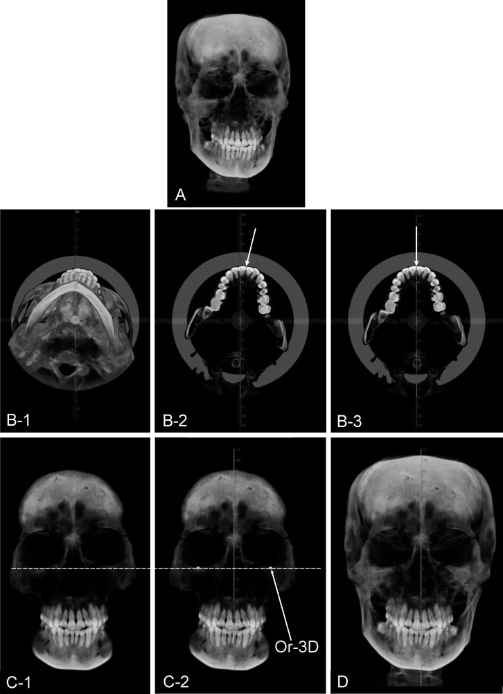
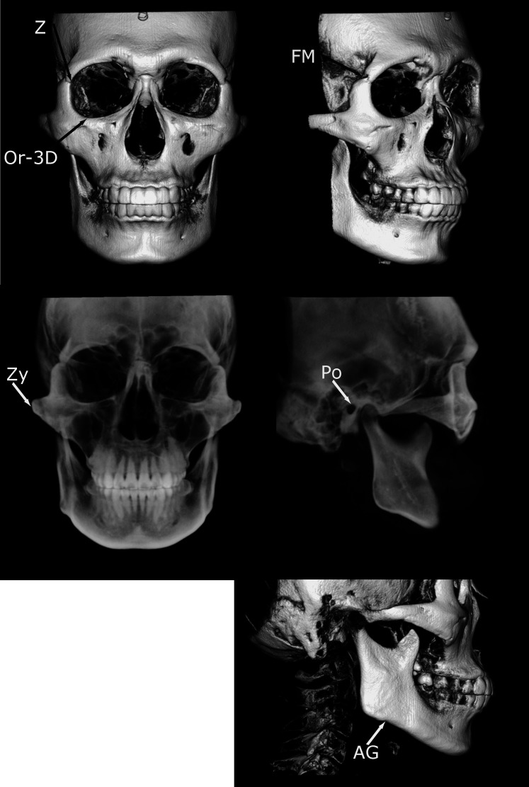
The CBCT images were reoriented with methods previously reported9 (Figure 1), and the vertical midline and horizontal reference planes were set accordingly. The antero-posterior line was not set because this study focused on asymmetry in the frontal view. After reorientation, bilateral anatomical landmarks of the skull were located, and the vertical and horizontal differences in their location in each group were compared by absolute values in millimeters. Landmarks used are summarized in Table 1 and Figure 2. Definition of the landmarks was modified from the study by Miyashita.13 According to the ease of visibility of each landmark, Z, Or-3D, FM, and AG were located with the images in bone mode and Zy and Po in teeth mode, preset by the manufacturer. All measurements were repeated within a 2-week interval, and intraclass correlations were calculated.
Figure 1.
(A) Initial cone beam computed tomography image. (B-1) Establishing the midsagittal plane in the axial section reorients the head image in the bottom view. (B-2) Clipping the axial section of the maxilla helps the operator determine the maxillary dental midline (white arrow) by visualizing the maxillary central incisors. (B-3) In this case, the maxillary dental midline coincided with the facial midline determined by clinical photos and examination. (C-1) After reorienting the head image to the frontal view, clipping the anterior part of the face in the coronal section aids in visualizing the lower borders of the orbital floors. (C-2) The horizontal reference plane (tangent dotted line) is established in maximum contact with the lower borders of the orbital floors. The Or-3D is indicated. (D) Final adjustment of head position after comparison with clinical photographs. All images are from Kook and Kim9 courtesy of the Journal of Clinical Orthodontics.
Table 1.
Definitions of Reference Points Used in This Study
Figure 2.
Illustrations and identification of landmarks used in this study.
Figure 3.
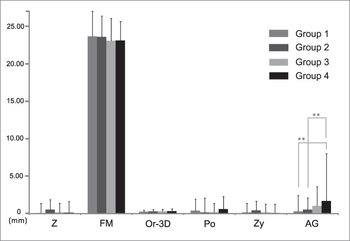
The vertical difference in the position of bilateral landmarks showed no statistically significant differences between groups, except for AG (** P < .001). Multiple comparison of AG indicated groups 1 and 2 had statistically significant differences compared with group 4, showing group 4 had significantly more vertical differences than groups 1 and 2 (one-way analysis of variance and Scheffé test).
Figure 4.
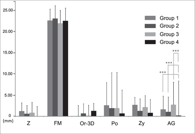
The horizontal difference in the position of bilateral landmarks showed no statistically significant differences between groups, except for AG (*** P < .0001). Multiple comparison of AG showed groups 1, 2, and 3 had statistically significant differences compared with group 4, indicating group 4 had statistically fewer horizontal differences than groups 1, 2, and 3 (one-way analysis of variance and Scheffé test).
Statistical Analyses
All reorientation procedures and measurements were repeated after 2 weeks by the same investigator, and the mean of the two measurements was used in the statistical analysis. The systematic intraexaminer error between the two measurements was determined using a paired t-test. In addition, the magnitude of the measurement error was assessed by calculating the intraclass correlation coefficient (ICC) based on a two-way mixed analysis of variance (ANOVA). For statistical analyses, the Mann-Whitney test, one-way ANOVA, and Scheffé test were used with a standard statistical software package (SAS version 9.1, Cary, NC). A P < .05 level of significance was used for all tests.
RESULTS
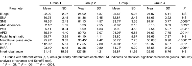
The systematic intraexaminer error was evaluated at P < .05 and found to be statistically insignificant. The ICC measurement indicated good reliability with a mean ICC of .925 (ICC = .620–.991). The mean ICC was .951 when the measurement of FM, which showed the largest standard deviation, was excluded. Cephalometric characteristics of the samples are described in Table 2 and showed statistically significant differences between group 1 and group 3 in the measurement for describing sagittal discrepancies, for example, SNB (P < .001), ANB difference (P < .05), and APDI (P < .05). Wits analysis showed a significant difference by one-way ANOVA and Scheffé test (P < .05); however, there was no statistically significant difference between groups by multiple comparison afterward. Group 3 showed statistically significant labioversion of upper incisors and linguoversion of lower incisors compared with group 1 (P < .05). In addition, groups 2 and 3 had a significantly steeper mandibular plane angle than did group 1 (P < .0001). In Table 2, groups with different letters (a, b) are significantly different from each other.
Table 2.
Comparison of Cephalometric Characteristics of the Samplea
Vertical Difference in the Position of Bilateral Landmarks
The vertical differences in the bilateral landmarks were compared by their absolute values. Table 3 and Figure 3 show no statistically significant differences between groups, except for AG (P < .001). Multiple comparison of AG indicated that groups 1 and 2 had statistically significant differences compared with group 4, showing that group 4 had significantly more vertical differences than did groups 1 or 2. Although there was no statistical test, the mean of the absolute value of difference was greatest at FM, and the value was clearly much larger than others. All groups had similar mean differences in other landmarks.
Table 3.
Mean Values of Vertical Differences in the Bilateral Landmark Locationa
Horizontal Difference in the Position of Bilateral Landmarks
Table 4 and Figure 4 show no statistically significant differences between groups, except for AG (P < .0001). Multiple comparison of AG showed groups 1, 2, and 3 had statistically significant differences compared with group 4, indicating that group 4 had statistically fewer horizontal differences than groups 1, 2, and 3. The mean of the absolute value of difference was also greatest at FM, and the values were clearly very much larger than others.
Table 4.
Mean Values of Horizontal Differences in the Bilateral Landmark Locationa
DISCUSSION
Proper evaluation of asymmetry depends on the accurate establishment of the horizontal or vertical reference plane in relation to the facial midline because the midline serves as the origin for measurements.14 With conventional PA cephalograms, the horizontal reference line is determined based on the superiorly located landmarks in the skull, followed by the vertical line mostly connecting crista galli, nasion, or dental midline, or vice versa.15 The landmarks used for setting up the horizontal reference line can be influenced by improper head positioning during PA cephalogram.6 The combined error of the magnification and distortion due to the divergent x-ray beam16 and incorrect head position produced inaccurate images.
The advanced 3D images enabled us to assess the spatial relationship of the dentofacial complex, rather than merely viewing in the antero-posterior dimension, providing the view of the so-called yaw, pitch, and roll.17 This leads to inconvenience in evaluation because all three axes are actually changeable, and it is up to the clinician to set up all three planes if he or she wants to evaluate asymmetry accurately, as head rotation introduces a misleading image. Although NHP has been advocated for a long time,18 it may be difficult to reproduce accurately the same NHP in 3D. In patients with asymmetry, NHP is not always ensured because compensating for head tilting is common.1 Therefore, we proposed a method of head reorientation based on the horizontal reference line of the inter–Or-3D line, which does not need to locate points.9 This may be more practical in clinical situations, but it was not known that these lines can also be used in asymmetric patients, in whom there may be a significant difference between the location of the right and left landmarks.
The prevalence of skeletal Class III malocclusion is considerably high in Korea,19 and several investigators reported a higher prevalence of facial asymmetry in skeletal Class III malocclusion patients.3,20 There are increasing numbers of Class III patients undergoing orthognathic surgery; therefore, it is of critical importance to assess asymmetry accurately in these patients. For this reason, groups 2 through 4 included skeletal Class III patients. Groups 1 and 2 represented the symmetric group with a different skeletal pattern, and groups 3 and 4 represented the asymmetric group, especially group 4 with severe asymmetry. The fact that there were no statistically significant vertical differences between groups in the location of landmarks in the upper and middle third of the skull indicated that all these landmarks, such as Z, FM, Or, Po, and Zyg, may be used in establishing the horizontal reference line. Nevertheless, FM showed remarkably large bilateral differences in all groups when compared with neighboring Z or Or-3D. Therefore, it is obviously clear that FM should not be recommended for setting up the horizontal reference line. One reason for this may be that FM is a point at the suture, and its location may vary depending on the change in brightness or contrast. More importantly, the gap at FM is usually larger than that at Z and is under large individual variation. This can be also confirmed by the same large bilateral differences in all four groups. In a clinical situation, Po should be located in the sagittal view in 3D; therefore, Or-3D may be easily used for setting the horizontal reference lines without locating landmarks but to rotate the head with the line in maximum contact with Or-3D. It was quite expected that AG would have a significant bilateral vertical difference; however, it may be a bit surprising that AG had less horizontal difference in group 4 than other groups, even less than group 1. This may imply that severe asymmetric patients included in group 4 have similar bilateral sizes in the horizontal dimension when measured at AG to the midsagittal line and have differences only in the vertical dimension. Further study may be necessary to arrive at a definite explanation. Also, it may be somewhat surprising that even Zy, which is not in the upper third of skull, had no statistically significant differences between groups. With the proper head orientation, Zy in itself did not show significant bilateral differences in its location, but the contour of the zygomatic arch may be different, and the reproducibility of Zy may be lower than other landmarks with sharp delineation.
It has been reported that measurements in 3D volumetric images only rather than simultaneously in sets of 2D multi-planar reconstruction (MPR) images introduces error because of the difficulty involved in locating landmarks in 3D and because of the inaccuracies of the user.21 In practice, locating landmarks by consulting 2D MPR images may take up too much time. Given the laborious process of locating landmarks in 3D, the time-benefit ratio of 3D analyses is likely to be lower than that of conventional 2D analyses. Another problem is that there are no generally accepted 3D definitions of the 2D landmarks. For example, landmarks such as sella and articulare are arbitrary and not anatomically present landmarks in 3D. Also, conventional orbitale located in the sagittal view may be different when located in the frontal view, which we have called Or-3D. Images of some landmarks at the suture area such as FM are dependent on contrast and brightness, and this should also be considered when choosing to use landmarks in 3D. It might be a stereotype of orthodontists that any cephalometric analysis should start from locating points and a line should come from two points. This fixed idea may lead to inaccuracy when evaluating with 3D images, which is inherently very accurate. A different and simple mode of analysis should be developed for 3D analysis with the full use of the knowledge accumulated by 2D cephalometric analyses. Finally, it is vitally important to readjust the skeletally constructed transverse plane by referring to clinical photographs and also to evaluate the soft tissue asymmetry at the same time.
CONCLUSIONS
The hypothesis is rejected. All groups had a similar pattern of asymmetry in the upper third of the face.
In the lower third of the face, a statistically significant difference was noted in the position of bilateral AG between groups.
Therefore, the transverse reference line of the bilateral Z or Or-3D may be used even in patients with severe asymmetry of the maxilla with reference to the clinical photos.
Acknowledgment
This study was partly supported by the alumni fund of the Department of Dentistry and Graduate School of Clinical Dental Science, Catholic University of Korea.
REFERENCES
- 1.Jacobson A. Radiographic Cephalometry From Basics to Videoimaging. Carol Stream, IL: Quintessence Publishing; 1995. [Google Scholar]
- 2.Trpkova B, Prasad N. G, Lam E. W, Raboud D, Glover K. E, Major P. W. Assessment of facial asymmetries from posteroanterior cephalograms: validity of reference lines. Am J Orthod Dentofacial Orthop. 2003;123:512–520. doi: 10.1067/mod.2003.S0889540602570347. [DOI] [PubMed] [Google Scholar]
- 3.Pirttiniemi P, Miettinen J, Kantomaa T. Combined effects of errors in frontal-view asymmetry diagnosis. Eur J Orthod. 1996;18:629–636. doi: 10.1093/ejo/18.6.629. [DOI] [PubMed] [Google Scholar]
- 4.Padwa B. L, Kaiser M. O, Kaban L. B. Occlusal cant in the frontal plane as a reflection of facial asymmetry. J Oral Maxillofac Surg. 1997;55:811–816. doi: 10.1016/s0278-2391(97)90338-4. [DOI] [PubMed] [Google Scholar]
- 5.Maeda M, Katsumata A, Ariji Y, Muramatsu A, Yoshida K, Goto S, Kurita K, Ariji E. 3D-CT evaluation of facial asymmetry in patients with maxillofacial deformities: oral surgery, oral medicine, oral pathology, oral radiology, and endodontics. 2006;102:382–390. doi: 10.1016/j.tripleo.2005.10.057. [DOI] [PubMed] [Google Scholar]
- 6.Yoon Y. J, Kim D. H, Yu P. S, Kim H. J, Choi E. H, Kim K. W. Effect of head rotation on posteroanterior cephalometric radiographs. Angle Orthod. 2002;72:36–42. doi: 10.1043/0003-3219(2002)072<0036:EOHROP>2.0.CO;2. [DOI] [PubMed] [Google Scholar]
- 7.Katsumata A, Fujishita M, Maeda M, Ariji Y, Ariji E, Langlais R. P. 3D-CT evaluation of facial asymmetry. Oral Surg Oral Med Oral Pathol Oral Radiol Endod. 2005;99:212–220. doi: 10.1016/j.tripleo.2004.06.072. [DOI] [PubMed] [Google Scholar]
- 8.Damstra J, Oosterkamp B. C. M, Jansma J, Ren Y. Combined 3-dimensional and mirror-image analysis for the diagnosis of asymmetry. Am J Orthod Dentofacial Orthop. 2011;140:886–894. doi: 10.1016/j.ajodo.2010.03.032. [DOI] [PubMed] [Google Scholar]
- 9.Kook Y. A, Kim Y. Evaluation of facial asymmetry with three-dimensional cone-beam computed tomography. J Clin Orthod. 2011;45:112–115. [PubMed] [Google Scholar]
- 10.Periago D. R, Scarfe W. C, Moshiri M, Scheetz J. P, Silveira A. M, Farman A. G. Linear accuracy and reliability of cone beam CT derived 3-dimensional images constructed using an orthodontic volumetric rendering program. Angle Orthod. 2008;78:387–395. doi: 10.2319/122106-52.1. [DOI] [PubMed] [Google Scholar]
- 11.Gribel B. F, Gribel M. N, Frazao D. C, McNamara J. A, Jr, Manzi F. R. Accuracy and reliability of craniometric measurements on lateral cephalometry and 3D measurements on CBCT scans. Angle Orthod. 2011;81:26–35. doi: 10.2319/032210-166.1. [DOI] [PMC free article] [PubMed] [Google Scholar]
- 12.Lou L, Lagravere M. O, Compton S, Major P. W, Flores-Mir C. Accuracy of measurements and reliability of landmark identification with computed tomography (CT) techniques in the maxillofacial area: a systematic review. Oral Surg Oral Med Oral Pathol Oral Radiol Endod. 2007;104:402–411. doi: 10.1016/j.tripleo.2006.07.015. [DOI] [PubMed] [Google Scholar]
- 13.Miyashita K. Contemporary Cephalometric Radiography. Tokyo, Japan: Quintessence Publishing; 1996. [Google Scholar]
- 14.Ras F, Habets L. L, van Ginkel F. C, Prahl-Andersen B. Method for quantifying facial asymmetry in three dimensions using stereophotogrammetry. Angle Orthod. 1995;65:233–239. doi: 10.1043/0003-3219(1995)065<0233:MFQFAI>2.0.CO;2. [DOI] [PubMed] [Google Scholar]
- 15.Grummons D. C, Kappeyne van de Coppello M. A. A frontal asymmetry analysis. J Clin Orthod. 1987;21:448–465. [PubMed] [Google Scholar]
- 16.Ahlqvist J, Eliasson S, Welander U. The effect of projection errors on cephalometric length measurements. Eur J Orthod. 1986;8:141–148. doi: 10.1093/ejo/8.3.141. [DOI] [PubMed] [Google Scholar]
- 17.Ackerman J. L, Proffit W. R, Sarver D. M, Ackerman M. B, Kean M. R. Pitch, roll, and yaw: describing the spatial orientation of dentofacial traits. Am J Orthod Dentofacial Orthop. 2007;131:305–310. doi: 10.1016/j.ajodo.2006.05.032. [DOI] [PubMed] [Google Scholar]
- 18.Lundstrom A, Lundstrom F, Lebret L. M, Moorrees C. F. Natural head position and natural head orientation: basic considerations in cephalometric analysis and research. Eur J Orthod. 1995;17:111–120. doi: 10.1093/ejo/17.2.111. [DOI] [PubMed] [Google Scholar]
- 19.Ryu Y. K, Kang H. K. A study on the prevalence of malocclusion of Yonsei University students in 1991. Korean J Orthod. 1992;22:691–701. [Google Scholar]
- 20.Sheats R. D, McGorray S. P, Musmar Q, Wheeler T. T, King G. J. Prevalence of orthodontic asymmetries. Semin Orthod. 1998;4:138–145. doi: 10.1016/s1073-8746(98)80015-7. [DOI] [PubMed] [Google Scholar]
- 21.Fuyamada M, Nawa H, Shibata M, Yoshida K, Kise Y, Katsumata A, Ariji E, Goto S. Reproducibility of landmark identification in the jaw and teeth on 3-dimensional cone-beam computed tomography images. Angle Orthod. 2011;81:843–849. doi: 10.2319/010711-5.1. [DOI] [PMC free article] [PubMed] [Google Scholar]


