

Abstract
Healing of nerve injuries is a critical medical issue. Biodegradable polymeric conduits are a promising therapeutic solution to provide guidance for axon growth in a given space, thus helping nerve heal. Extensive studies in the past decade reported that conductive materials could effectively increase neurite and axon extension in vitro and nerve regeneration in vivo. In this study, graphene oxide and carbon nanotubes were covalently functionalized with double bonds to obtain crosslinkable graphene oxide acrylate (GOa) sheets and carbon nanotube poly(ethylene glycol) acrylate (CNTpega). An electrically conductive reduced GOa-CNTpega-oligo(polyethylene glycol fumarate) (OPF) hydrogel (rGOa-CNTpega-OPF) was successfully fabricated by chemically crosslinking GOa sheets and CNTpega with OPF chains followed by in situ chemical reduction in L-ascorbic acid solution. Scanning electron microscopy (SEM) and transmission electron microscopy (TEM) imaging showed homogenous distribution of GOa/CNTpega carbon content in the rGOa-CNTpega-OPF composite hydrogel, resulting in a significant increase of electrical conductivity compared with neutral OPF without carbon content. Cell studies showed excellent biocompatibility and distinguished PC12 cell proliferation and spreading on the rGOa-CNTpega-OPF composite hydrogel. Fluorescent microscopy imaging demonstrated robustly stimulated neurite development in these cells on a conductive rGOa-CNTpega-OPF composite hydrogel compared with that on neutral OPF hydrogels. These results illustrated a promising potential for the rGOa-CNTpega-OPF composite hydrogel to serve as conduits for neural tissue engineering.
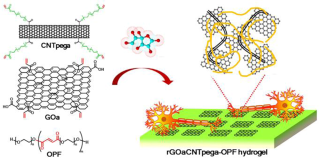
Graphical Abstract
Chemically crosslinking GOa and CNTpega followed by in situ reduction fabricated a conductive rGOa-CNTpega-OPF hydrogel that strongly stimulated neurite growth.
1. Introduction
Peripheral nerve repair is an important medical issue in the United States and Europe with around 100,000 nerve repair surgeries being performed annually.1 Multiple injuries and pathologies could damage peripheral nerve, including congenital defects, cancer or trauma, making nerve repair highly demanded for a fairly long time in the predictable future.2 Among these injuries, the short ones (less than 1 cm damage) have a fairly good treatment using nerve guidance channels or microsutures.3, 4 However, for the longer damages, it is still a challenging clinical issue to find effective ways to successfully reconnect the two nerve ends over large distances. Nerve tissue engineering using synthetic conduits has demonstrated a promising potential in helping regeneration of new nerve axons and functional recovery to a certain degree.5–7
Biodegradable polymers are promising candidates for nerve guidance conduits. In the past decades, various natural and synthetic polymers were evaluated as conduits for nerve regeneration, including chitosan, collagen, fibrin, poly-lactic-co-glycolic acid (PLGA), poly-L-lactide acid (PLLA), polycaprolactone (PCL), and poly(caprolactone fumarate) (PCLF)8–20. Poly(ethylene glycol) (PEG) is a biocompatible hydrophilic polymer widely used for cancer imaging, drug delivery, and fabrication of hydrogel scaffolds for nerve tissue engineering.21–25
As a crosslinkable derivative of PEG, oligo(polyethylene glycol fumarate) (OPF), is synthesized by linking PEG chains using fumaric acid with unsaturated double bonds.26, 27 When exposed to UV light or chemical crosslinking reagents such as ammonium persulfate (APS) and N,N,N′,N′-tetramethylethylenediamine (TEMED), the unsaturated double bonds in OPF chains are able to open and link with each other to form a crosslinked network. The crosslinked OPF hydrogel was reported to be biocompatible under both in vitro and in vivo conditions and could be biodegraded through simple hydrolysis.28, 29 The cross-linking density, modulus and surface charges of crosslinked OPF hydrogel can be tailored in response to various tissue engineering applications.30 In our previous study, OPF hydrogels were fabricated in hollow tubes and nerve regeneration was observed after implantation into a rat sciatic nerve model.20
Currently reported systems, though promising, are far from being optimal with large room for improvement. Introducing conductive components into the scaffolds to render the conduit electrically conductive is acknowledged to be an effective way to enhance neuronal cell responses in vitro and stimulating axon growth in vivo.31, 32 For example, after incorporating conductive polypyrrole (PPy), the poly(L-lactic acid) (PLLA)/PPy, poly(lactic-co-glycolic acid) (PLGA)/PPy, chitosan/PPy or cellulose/PPy conductive composite materials were reported to better stimulate neurite outgrowth and axon regeneration than the original nonconductive polymer form.33–40 Moreover, in situ precipitation of conductive polyaniline (PANi) in polyethyleneglycol diacrylate (PEGDA) solution, followed by photocrosslinking generated a hybrid conductive PANi/PEGDA hydrogel, which were reported to improve the biological response of both PC12 cells and human mesenchymal stem cells (hMSCs).41
Graphene sheets and carbon nanotubes are widely used conductive carbon materials. In recent years, an increasing amount of research has extended the application of conductive graphene sheets, single wall carbon nanotubes, and multiwall carbon nanotubes into neuron tissue engineering.42–44 Results demonstrated that incorporating conductive carbon content could produce biocompatible conductive scaffolds or hydrogels with an enhanced effect for nerve cell behaviors.45–49 However, graphene sheets and carbon nanotubes easily form aggregates when dispersed in solutions, particularly in viscous polymeric mixture solutions. The aggregation of graphene/CNT will result in heterogeneous distribution and thus anisotropic conductivity in the hydrogel. In addition, for hydrogels fabricated with carbon content without chemical bonding, the graphene/CNT is simply maintained in the hydrogel by physical entanglement. When exposed to aqueous solutions, the conductive hydrogel swells and weakens the physical entrapment of carbon materials, which may result in the release of these carbon materials from the hydrogel.
In this study, we functionalized multiwall carbon nanotubes with PEG chains to prevent aggregation and introduced acrylate bonds (CNTpega) to make the carbon nanotube crosslinkable. The GO sheets were also functionalized with small amounts of acrylate groups on the surface to become crosslinkable GOa sheets. Synthesized materials were characterized by attenuated total reflectance Fourier transform infrared spectroscopy (ATR-FTIR), thermogravimetric analysis (TGA), scanning electron microscopy (SEM) and atomic force microscopy (AFM). To fabricate hydrogel scaffolds (Fig. 1a–c), all three types of crosslinkable components, i.e., OPF, GOa and CNTpega, were homogeneously mixed and chemically crosslinked, followed by soaking in L-ascorbic acid solution for in situ reduction of GOa (rGOa). Conductivities of hydrogels were calculated by determining the resistivity of a cuboid sample with defined height, width and length. The distribution of rGOa/CNTpega carbon contents in fabricated hydrogels were characterized by transmission electron microscopy (TEM). The biological compatibility and effectiveness in stimulation of PC12 cell adhesion, proliferation and neuronal differentiation for the composite hydrogels was further evaluated. Enhanced nerve cell responses were observed on a conductive rGOa-CNTpega-OPF composite hydrogel, which is schematically demonstrated in Fig. 1d–e.
Fig. 1.
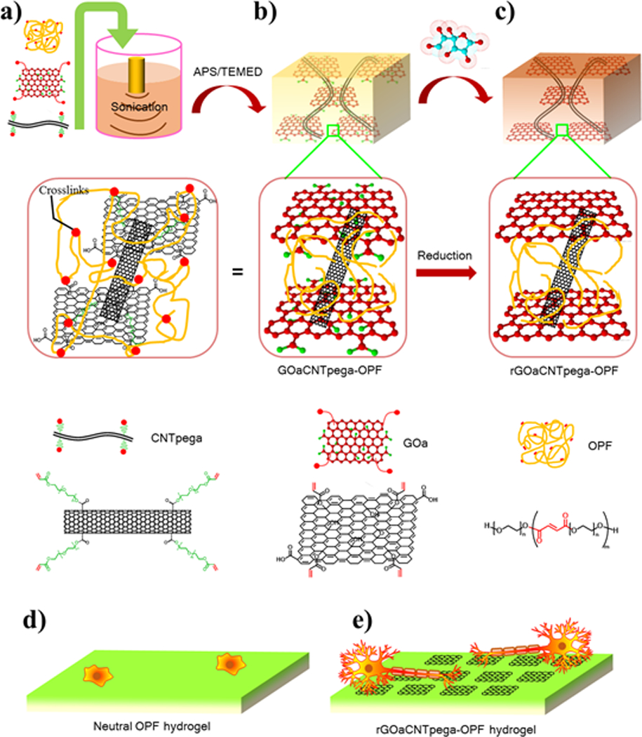
Fabrication of conductive rGOaCNTpega-OPF composite hydrogel. a) Mixing of GOa, CNTpega and OPF by sonication. b) Crosslinking of the mixture to form composite GOaCNTpega-OPF hydrogel. c) In situ reduction of GO sheets in L-ascorbic acid solution to obtain final rGOaCNTpega-OPF composite hydrogel. Schematic of nerve cells growing and differentiating on the d) neutral OPF hydrogel and e) conductive rGOaCNTpega-OPF composite hydrogel.
2. Materials and Methods
2.1. Materials
Graphite flakes (~150 μm flakes), concentrated phosphoric acid (H3PO4), concentrated sulfuric acid (H2SO4), hydrochloric acid, potassium permanganate (KMnO4), 30% hydrogen peroxide, triethylamine (TEA), anhydrous N,N-dimethylformamide (DMF) and carboxylic acid functionalized multi-wall carbon nanotube (CNT-COOH, >8% carboxylic acid functionalized, average diameter × L = 9.5 nm × 1.5 μm) were purchased from Sigma Aldrich Co. (Milwaukee, WI). Ammonium persulfate, L-ascorbic acid, N,N,N′,N′-tetramethylethylenediamine (TEMED) and acryloyl chloride (≥97%, containing ~400 ppm phenothiazine as a stabilizer) were purchased from Sigma Aldrich and used as received. Poly(ethylene glycol) (average M.W. 1000) was purchased from Acros Organics (Pittsburgh, PA). Commonly used solvents for organic synthesis were purchased from Fisher (Pittsburgh, PA). LIVE/DEAD® Viability/Cytotoxicity Kit for mammalian cells was purchased from Thermo Fisher Scientific (Pittsburg, PA). All other materials or chemicals were purchased from Fisher or Sigma unless noted otherwise.
2.2. Synthesis of GOa sheets
Graphene oxide was synthesized from natural graphite flakes (~150 μm flakes) using improved Hummers’ method.50 Briefly, a mixture of concentrated H2SO4/H3PO4 (360 mL/40 mL) was carefully added into a three-neck flask placed in an ice bath. Graphite flakes (3 g) were added, and 18 g of KMnO4 was then added with vigorous stirring for 10 min. The reaction mixture was then transferred into an oil bath, heated to 50 °C and kept under constant stirring for 12 h. The reaction was subsequently cooled to room temperature and poured into a glass beaker with ~800 mL ice and 3 mL of 30% H2O2. The oxidized mixture was sifted through a 250-μm U.S. Standard testing sieve and filtered by a polyester fiber to remove non-oxidized graphite. The supernatant was centrifuged for 20 min at 4000 rpm. The precipitant was collected and washed once with 400 mL of 30% HCl, followed by washing three times with 400 mL of ethanol. After each wash, the mixture was sifted through the U.S. Standard testing sieve, filtered by a polyester fiber, and centrifuged at 4000 rpm for 20 min. Collected graphene oxide was then dispersed in deionized water by ultrasonication using a probe model sonicator (Qsonica Q500) and dialyzed in a cellulose dialysis bag (MWCO 2000) against excess deionized water for three days to remove acid and metal residues. Purified graphene oxide solution was dried in vacuum at ambient temperature and stored at −20 °C prior to use.
Purified GO sheets (1 g) were added into 150 mL of anhydrous DMF and ultrasonicated for 10 min. The exfoliated GO/DMF mixture was then transferred into a three-neck flask placed in an ice bath and flushed with nitrogen for 10 min. Excess Et3N (1 mL) was added and 40 μL of acryloyl chloride was injected dropwise using a syringe under vigorous stirring. Acryloyl chloride and DMF may react severely at high temperature and thus this step must be operated at a low temperature and acryloyl chloride must be injected slowly. After acryloyl chloride was injected, the system was gradually warmed up to room temperature and kept stirring for 24 h under nitrogen. The reaction system was then precipitated twice in excess acetone and twice in ethanol to remove acryloyl chloride and DMF solvent. Obtained GOa was dialyzed against deionized water in a cellulose dialysis bag (MWCO 2000) for three days to remove residue ions and small molecules. The purified product was dried in vacuum at ambient temperature and stored at −20 °C before usage.
2.3. Synthesis of CNTpega tubes
To functionalize carbon nanotubes, 0.1 g of CNT-COOH was added into 30 mL of DMF and sonicated for 10 min. Excess HO-PEG-OH polymer (4.0 g) with 1000 g mol−1 molecular weight was dissolved in 20 mL DMF and mixed with the CNT-COOH solution. Then, 0.25 g of dicyclohexylcarbodiimide (DCC) and 0.25 g of 4-dimethylaminopyridine (DMAP) were added and the reaction was stirred at 120 °C for 24 h. After completion, the mixture was washed with excess acetone (twice), water (twice) and acetone (twice) followed by centrifugation at 3000 rpm for 10 min to remove unreacted HO-PEG-OH polymer chains and other residuals. The obtained CNTpeg materials were dried by lyophilization and stored at −20 °C. To add crosslinkable acrylate groups, 0.1 g of CNTpeg materials was disbursed in 30 mL of DMF by sonication. Then, 1 mL of Et3N and 0.5 mL of acryloyl chloride were added with vigorous stirring at 0 °C, and the reaction was maintained for two days under nitrogen at room temperature. The obtained CNTpega was precipitated twice in excess acetone and ethanol then dried by lyophilization and stored at –20 °C prior to use.
2.4. Fabrication of composite hydrogels
The OPF polymer was synthesized according to previously reported procedures.51, 52 Slight modifications were made by altering the toxic triethylamine into nontoxic potassium carbonate (K2CO3) as a proton scavenger in the reaction system, as described in Fig. S1. Briefly, 50 g of PEG (average M.W. 1000) was dissolved in 400 mL CH2Cl2 in a three-neck flask purged with nitrogen gas. The flask was then transferred into an ice bath for cooling down the temperature to ~0 °C. Then, excess K2CO3 (20 g) was added as a proton scavenger, followed by the dropwise addition of 6.75 mL fumaryl chloride. The reaction was kept stirring at room temperature for 24 hours then centrifuged at 3000 rpm for 10 min to remove unreacted K2CO3 solids and precipitated in diethyl ether to yield OPF polymer. To fabricate neutral OPF hydrogel, 1 g of OPF polymer and 36 mg of N,N′-methylenebis(acrylamide) (MBA) were added to 2 mL of deionized H2O and mixed homogenously by vortexing. Then, 0.1 mL of APS solution (1 g APS in 2 mL deionized H2O) was added and mixed thoroughly. The OPF/MBA/APS solution was transferred into silicone rubber molds (0.8 mm thickness) on a glass slide. To accelerate the chemical crosslinking process, 0.1 mL of TEMED solution (1 mL TEMED in 2 mL H2O) was added and mixed together with the polymer solution. The mold was then covered with another glass slide and placed in a 60 °C oven for 1 hour to allow the mixture to fully crosslink. To fabricate conductive hydrogels, 0.1 g of GOa sheets was added into 10 mL of deionized H2O and was sonicated for 10 min to obtain 10 mg mL−1 GOa solution. Afterwards, 0.01 g of CNTpega was added and sonicated for another 10 min to obtain a GOa-CNTpega mixture solution. GOa-CNTpega-OPF hydrogel was fabricated by mixing 1 g of OPF and 36 mg of MBA with 2 mL of the above prepared GOa-CNTpega solution and crosslinked using APS and TEMED, following the same procedure as described previously. After crosslinking, all hydrogels were immersed in excess deionized H2O for two days with water changed every 12 hours to remove residual impurities. To make GOa-CNTpega-OPF conductive, hydrogel samples were soaked in 10 mg mL−1 L-ascorbic acid solution for two days with gentle shaking at 37 °C. The reduced rGOa-CNTpega- hydrogel was then washed with excess deionized H2O for three days with water changed every 8 hours.
2.5. Material Characterizations
Atomic force microscopy (AFM).
The morphology and layer height were analyzed by nanoscale AFM measurements. The graphene oxide sample (~1 μg mL−1) was deposited on a freshly cleaved mica surface, incubated for a couple of minutes, and then gently dried under a nitrogen stream. AFM images were obtained in tapping mode using a Nanoscope IV PicoForce Multimode AFM (Bruker, Santa Barbara, CA) equipped with an E-scanner and a rectangular-shaped silicon cantilever with a 42 N/m spring constant and a resonant frequency of ~300 kHz in an ambient environment.53, 54
Fourier transform infrared spectroscopy (FTIR).
The synthesized GO, GOa and CNTpega materials were characterized by ATR-FTIR on a Nicolet Continuum Infrared Microscope (Thermo Scientific) with detecting wavenumber from 650 to 4000 cm−1.
Scanning electron microscopy (SEM).
To observe the morphological structures, the two types of hydrogels were dried by lyophilization and broken open using forceps after freezing in liquid nitrogen. Prepared specimens were sputter coated with gold–palladium and viewed by SEM (S-4700, Hitachi Instruments, Tokyo, Japan).
Transmission electron microscopy (TEM).
The morphology of reduced GOa sheets and CNTpega tubes in the crosslinked composite hydrogels was observed by TEM (1200-EX II, JEOL Inc., Japan). Before viewing, the two types of dried composite hydrogel specimens were buried into resin and sectioned into 0.6 μm thick blocks with a glass knife. The thick blocks were further sectioned into 0.1 μm layers with a diamond knife and viewed with the TEM at 80 kV voltage.
Conductivity test.
Deionized water was further purified by a Millipore system to remove as many unwanted ions and impurities as possible. Prior to the conductivity study, both types of hydrogels were immersed in purified deionized water for three days with the water changed at least five times to remove impurities and ions created during the fabrication process. Then, the hydrogels were cut into rectangular sheets and the length (L), width (W) and height (H) were measured. The electrical resistance of these hydrogel sheets was measured with a Fluke 73 multimeter and marked as R. Sheet resistivity was calculated using the following equation:
where ρ is resistivity and A is the cross-sectional area of hydrogel specimen. Hydrogel conductivity (σ) was calculated as the inverse of hydrogel resistivity, , with unit of siemens per meter (S/m).
2.6. Cytotoxicity of composite hydrogels
After crosslinking, the hydrogels were placed in deionized water for two days with the water changed three times to remove uncrosslinked polymers and crosslinking agents. Cleaned hydrogels were then sterilized with 70% alcohol overnight and washed thoroughly with sterilized phosphate buffered saline (PBS) for three days with the PBS changed at least five times. PC12 cells (ATCC, Manassas, VA) were used for biological evaluation and cultured in Dulbecco’s modified Eagle’s medium (DMEM) supplemented with 5% fetal bovine serum, 10% horse serum, and 0.5% streptomycin/penicillin. Prior to co-culture with hydrogels, the cells were maintained in a flask with 10 mL of medium and placed in a cell culture incubator set at 95% relative humidity, 5% CO2 and 37 °C. Following trypsinization, PC12 cells were counted and re-suspended in DMEM supplemented with 50 ng mL−1 NGF and seeded at 30000 cells cm−2 in 12-well tissue culture polystyrene (TCPS) plates. After 24 h of culture allowing for cellular attachment, transwells (mesh size 3 μm) containing varied hydrogels were introduced into the wells. After co-culturing for four days, the number of cells in each well was quantified by an MTS assay kit (CellTiter 96, Promega, Madison, WI). The absorbance at 490 nm was read by a UV-Vis absorbance micro plate reader (SpectraMax Plus 384, Molecular Devices, Sunnyvale, CA). Cell viability (%) in wells treated by different composite hydrogels was determined by comparing to positive control wells without incorporating hydrogel samples (set as 100%).
2.7. PC12 cell proliferation
Crosslinked hydrogels were washed with deionized water to remove sol fraction and sterilized with 70% alcohol, as described above. To evaluate cell proliferation rates of these hydrogels, both types of hydrogels were punched into round disks with the same 13.2 mm diameter using a cork borer. To prevent floating or moving in the cell culture medium, hydrogel disks were firmly glued to the bottom of 12-well tissue culture plates using sterilized vacuum grease (Dow Corning, Midland, MI). Prior to cell seeding, hydrogel disks were immersed in a DMEM cell culture medium supplemented with 50 ng mL−1 NGF for 2 hours to allow slow diffusion of medium into the hydrogel. The medium was then removed and cells were seeded onto the hydrogels at a density of 30000 cells cm−2. After 1, 4, and 7 days of post-seeding, the cell culture medium was removed and the hydrogel disks were washed twice with PBS. Cell numbers on each hydrogel sample were quantified using the MTS assay. The optical absorbance at 490 nm was detected by a UV-Vis absorbance micro plate reader as described above.
2.8. Neuronal differentiation
To observe cellular morphological features and neurite development, PC12 cells were stained by a live/dead assay and visualized using a fluorescent microscope, according to previous reports.55 Briefly, PC12 cells were seeded at the same density as in the proliferation study and allowed to grow for 4 days on the hydrogels in DMEM supplemented with 50 ng mL−1 NGF. Then, the cell medium was removed and the cells were washed twice with PBS and stained using a LIVE/DEAD® Viability/Cytotoxicity Kit (Thermo Fisher Scientific) following the protocol. The morphology of stained cells was viewed and photographed using an Axiovert 25 Zeiss light microscope (Carl Zeiss, Germany). Red-fluorescent ethidium homodimer-1 was able to mark the loss of plasma membrane integrity, thus indicating the number of dead cells. The green-fluorescent calcein-AM was functionalized to indicate intracellular esterase activity and thus could identify the whole cellular boundaries of live cells. After obtaining the fluorescent images, the cell spreading area, percentage of cells bearing neurites, and average neurite length were quantified using ImageJ software.
2.9. Statistical analysis
Statistical analysis of data from different groups was performed using one-way analysis of variance (ANOVA) and additional Tukey post-test if necessary. Groups calculated to have p-values smaller than 0.05 were considered to be significantly different.
3. Results and Discussion
3.1. Covalently functionalized GOa and CNTpega
The GO precursor sheets and crosslinkable GOa sheets were successfully synthesized according to the steps in Fig. 2a. ATR-FTIR spectra of the obtained GO showed main peaks for the corresponding functional groups on GO sheets, including hydroxyl (-OH), carboxyl (-COOH), epoxyl (C-O) and tiny amounts of double bond groups. After acrylation using acryloyl chloride, a significant increase in acrylate groups (C=C, wavenumber ~ 1649 cm−1) were detected for the GOa sheets, indicating successful incorporation of crosslinkable double bonds to the GO sheets (Fig. 2b). AFM analysis showed GO sheets detected at an approximately 1 nm height, demonstrating that GO was successfully exfoliated into the single layered sheets (Fig. 2c). After acrylation, the GOa sheets displayed a similar value of around 1 nm layer height, which is presented in Fig. 2d.
Fig. 2.
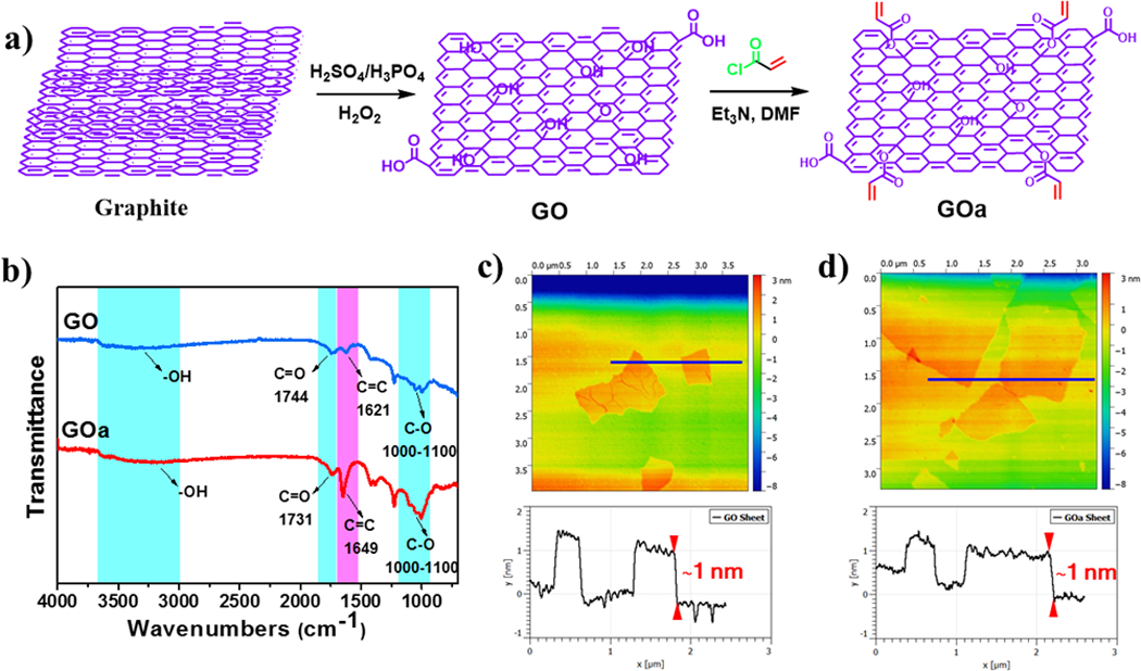
Synthesis and characterization of GOa and CNTpega. a) Synthesis route of GOa. b) ATR-FTIR spectra of obtained GO and GOa sheets. AFM analysis of morphology and layer height of c) GO and d) GOa sheets.
CNT with carboxyl functional groups were further modified with PEG1000 chains through an esterification reaction between the carboxyl groups in CNT and the hydroxyl groups in PEG (Fig. 3a). The obtained CNTpeg materials were further acrylated by reaction with acryloyl chloride, which introduces double bonds to the CNTpeg and generates the final crosslinkable CNTpega product. As shown in Fig. 3b, the ATR-FTIR spectrum of CNT-COOH received from Sigma showed only few tiny peaks possibly due to the small amount of carboxyl groups (8%) functionalized on the surface. After the reaction, ATR-FTIR analysis showed a typical peak for PEG chain at wavenumber between 2828 and 2890 cm−1 and a small peak for acrylate groups at wavenumber around 1649 cm−1, as demonstrated in Fig. 3b. This indicates the successful incorporation of PEG chains and acrylate groups to the CNTs. Thermal degradation of CNT-COOH and CNTpega under temperatures ramping from ~25 to 700 °C was analyzed by TGA. As seen in Fig. 3c, at 700 °C, CNT-COOH had around 10% mass loss. However, for CNTpega, the mass loss was much higher with a value close to 15%. This is due to the burn out of the PEG segment and acrylate groups at high temperatures. The morphology and size of the CNT-COOH and CNTpega materials were viewed by SEM. As shown in Fig. 3d and 3e, the CNT-COOH and CNTpega adopted similar morphological features and close size distribution in the 5–30 nm range.
Fig. 3.

a) Synthesis steps for obtaining CNTpega material. b) ATR-FTIR spectra and c) thermal degradation analysis of CNT-COOH and CNTpega material by TGA. SEM micrographs of d) CNT-COOH and e) CNTpega materials.
3.2. Fabrication and characterization of composite hydrogel
For neutral OPF hydrogel, no conductive GOa/CNTpega carbon content was incorporated. As demonstrated in Fig. 4a, this type of hydrogel is transparent and composed solely of the polymeric networks. To render them electrically conductive, crosslinkable GOa sheets and CNTpega tubes were incorporated into the polymer network followed by in situ reduction of GOa sheets in L-ascorbic acid solution. As seen in Fig. 4b, the generated rGOaCNTpega-OPF hydrogel showed an opaque dark color, resulting from the carbon content inside the hydrogel.
Fig. 4.

Fabricated a) OPF and b) rGOaCNTpega-OPF hydrogels. c) Electrical conductivity of neutral OPF and rGOaCNTpega-OPF hydrogels. The morphology of freeze-dried hydrogel was observed by SEM for d) OPF and e) rGOaCNTpega-OPF. After sectioning into thin layers, the hydrogels were observed by TEM for both f) OPF and g) rGOaCNTpega-OPF.
The hydrogel conductivities were tested after soaking in deionized water for three days to remove impurities. As noted from Fig. 4c, millipore deionized water, which was used as a control, was tested to have conductivity of approximately 6.8 ± 5.7 × 10⁻⁵ siemens per metre (S/m). According to previous reports, the conductivity of deionized water upon full equilibration to the atmosphere was around 7.5 × 10⁻⁵ S/m.56. This is highly believed to be caused by the dissolution of CO2 from air into water, which generates a small amount of H2CO3 acid and produces a slight conductivity in the deionized water. Our value tested was close to the reported value at the same magnitude. As shown in Fig. 4c, the neutral OPF hydrogel was determined to have a conductivity of 2.0 ± 1.3 × 10⁻⁴ S/m. For rGOaCNTpega-OPF hydrogel incorporated with carbon content, the conductivity was significantly increased to 7.9 ± 6.2 × 10⁻³ S/m. This enhancement is mainly contributed by the conductive rGOa and CNTpega carbon components.
SEM images of the edges of the hydrogels are demonstrated in Fig. 4d–e. The neutral OPF hydrogel showed solidified internal layers. However, for the rGOaCNTpega-OPF hydrogel incorporated with carbon content, a more rough structure with tubes and sheets was observed inside the hydrogel substrates. This was believed to be caused by the rigid GOa/CNTpega carbon content in the hydrogel.
To explore the distribution of GOa/CNTpega carbon contents within the hydrogels, the composite hydrogels were sectioned into 0.1 μm thin layers and visualized by TEM. As seen in Fig. 4f, the OPF hydrogels without GOa/CNTpega carbon content showed high transparency under TEM. However, for the rGOaCNTpega-OPF hydrogels, the imaged layers were generally in dark color, resulting from the presence of GOa/CNTpega (Fig. 4g). Enlarged views showed an even distribution of GOa sheets and CNTpega tubes in the hydrogel without forming large aggregates.
3.3. Hydrogel Cytotoxicity and PC12 cell proliferation
Cytotoxicity of the hydrogels to PC12 cells was evaluated by MTS assays after 1, 4 and 7 days of co-culture. The results demonstrated that neither of the hydrogels showed cytotoxicity with high cell viability similar to the TCPS control (Fig. 5a). The proliferation of PC12 cells on these hydrogels as well as TCPS positive control were also investigated after 1, 4 and 7 days of post-seeding. As shown in Fig. 5b, the TCPS positive control showed the highest value, whereas the lowest OD absorbance was observed for neural OPF hydrogel. Compared with the neural OPF hydrogel, the conductive rGOaCNTpega-OPF hydrogel showed significant higher (p < 0.05) adsorption at both day 4 and 7 of post-seeding. These results indicate that the conductive rGOaCNTpega-OPF hydrogel is biocompatible and could effectively support and stimulate cellular growth. This trend is consistent with one of our previous study that reported enhanced PC12 cell growth on a OPF/PPy conductive hydrogel. 57
Fig. 5.
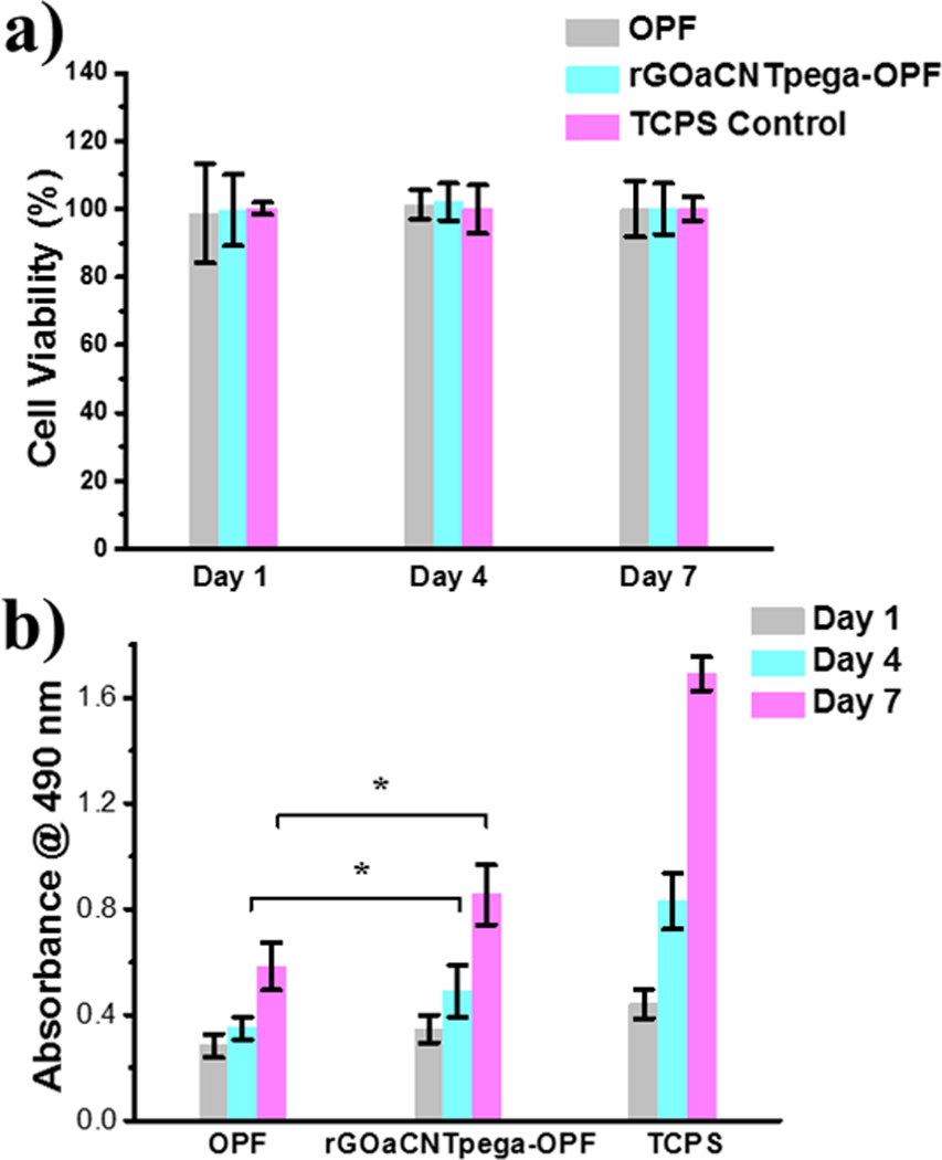
a) PC12 cell viability determined using MTS assay after 1, 4 and 7 days co-culture with OPF or rGOaCNTpega-OPF hydrogels compared to TCPS positive control. b) MTS absorbance determined @ 490 nm after day 1, 4, and 7 days post-seeding of PC12 cells onto OPF or rGOaCNTpega-OPF hydrogel scaffolds. *denotes significant difference (p < 0.05) between OPF and rGOaCNTpega-OPF groups at day 4 and 7.
3.4. Neuronal differentiation of PC12 cells
To observe live/dead cell distribution and live cell morphology, PC 12 cells cultured on OPF hydrogels were analyzed using a live/dead cell assay. After incubation, the live cells on the hydrogel were stained with green fluorescence, whereas the dead cells were stained with red color. As shown in Fig. 6a and 6b, both neutral OPF and conductive rGOaCNTpega-OPF hydrogels showed primarily green fluorescent live cells, confirming the cytocompatibility of both hydrogels. Furthermore, the conductive rGOaCNTpega-OPF hydrogel showed much denser cell distribution on the surface. These results were highly consistent with the higher cell proliferation rate determined by the MTS assay.
Fig. 6.
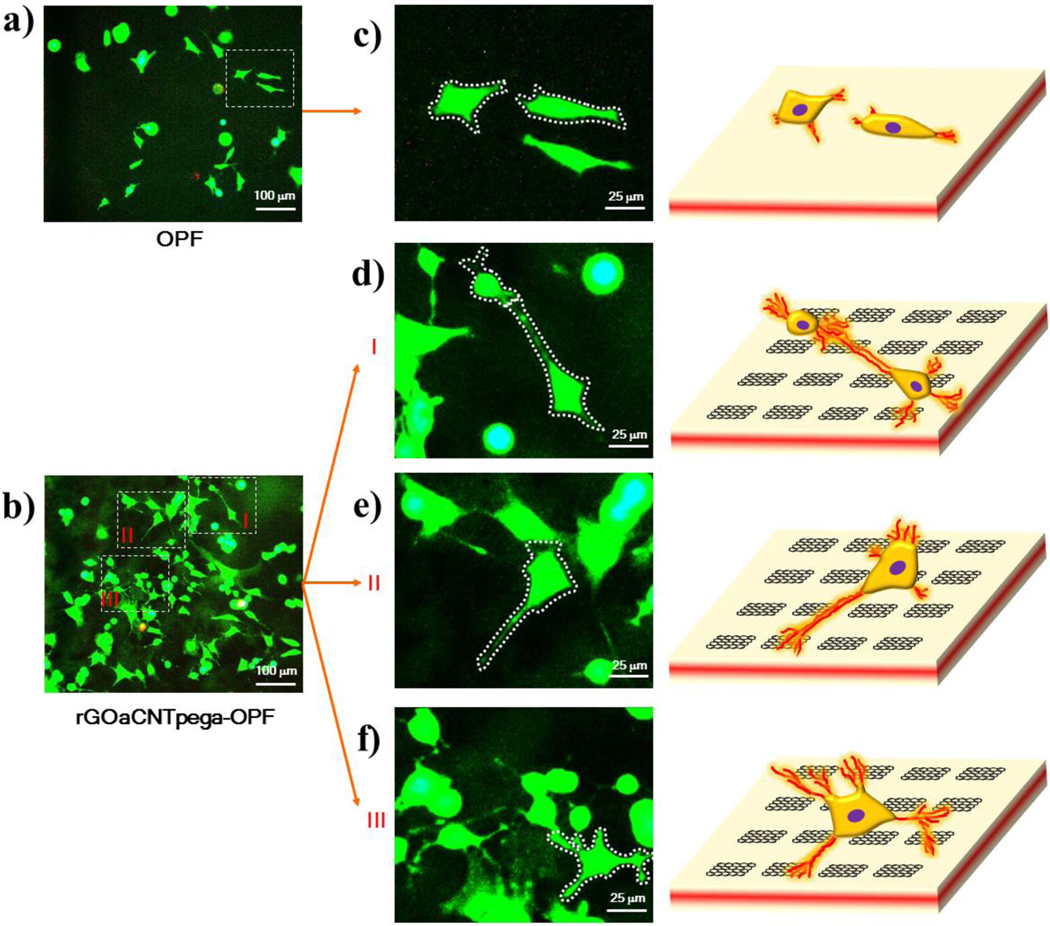
Live (green) and dead (red) staining of PC12 cells on a) OPF and b) rGOaCNTpega-OPF hydrogels. Fluorescent images as well as schematic of single live cells on c) OPF and d-f) rGOaCNTpega-OPF hydrogels are presented to identify the neurite development from the cell bodies.
Enlarged views of non-overlapping single cells on these hydrogels are shown in Fig. 6c for the OPF hydrogel and Fig. 6d–f for the rGOaCNTpega-OPF hydrogel. Clear neurite extension can be found for cells on the rGOaCNTpega-OPF hydrogel functionalized with inherent conductivities compared to the neutral OPF hydrogel. As demonstrated in Fig. 6c, PC12 cells on OPF hydrogels had an extended cell body and initial development of neurites from cell membranes. Schematic of the two typical cells on OPF hydrogels is also presented. In contrast, cells on conductive rGOaCNTpega-OPF hydrogel had much more robustly developed neurites with higher neurite numbers per cell and longer neurite lengths. Schematic of several typical cells with nerites developed on the conductive rGOaCNTpega-OPF hydrogel is presented in Fig. 6d–f.
Quantitative analysis of PC12 cell spreading and neurite development on these hydrogels was conducted. As demonstrated in Fig. 7a, the cell area distribution of 50 single cells on these hydrogels was analyzed and averaged. Cells on neutral OPF hydrogels showed limited spreading with an average value of 886 ± 392 μm2. With conductive properties, the rGOaCNTpega-OPF hydrogel supported cell spreading much better with an average spreading area of 1129 ± 611 μm2 on the hydrogel. These results indicate that the inherent conductivity of substrates could significantly enhance the cell spreading functions.
Fig. 7.

a) Distribution and average value of cellular spreading area calculated from 50 single cells at 4 days post-seeding on different hydrogels. b) Percent of neurite bearing PC12 cells at 4 days post-seeding on these hydrogels. c) Neurite length distribution and average value for 100 independent neurites developed in cells growing on these hydrogels.
The percent of neurite bearing cells on the two types of hydrogels were also calculated. As presented in Fig. 7b, on neutral OPF hydrogels, approximately 20.5% ± 7.5% of the cells developed neurites. However, with the introduction of conductivity properties, the functionalized rGOaCNTpega-OPF hydrogel showed a significant higher percentage of neurite bearing cells than the neutral OPF hydrogels with values of 31.8% ± 8.4%. These results demonstrated that inherent conductivity could robustly help the neuronal differentiation of PC12 cells on the OPF hydrogels. Compared with the conductive poly(D, L-lactic acid) (PDLLA) system incorporated with 5%−15% PPY, which reported ~ 13% of PC12 cells bearing neurites,58 our rGOaCNTpega-OPF hydrogel showed fairly good or even better induction of neurite development. This trend agrees well with multiple previous studies, which reported a strong enhancement of nerve cell behaviors on substrates incorporated with carbon nanotubes for nerve tissue engineering.48, 49, 59–62
The neurites lengths were characterized by measurement of independent neurites developed from cell bodies using the ImageJ software. As shown in Fig. 7c, the length distribution of 100 independent neurites developed in cells on the two types of hydrogels showed apparent differences. On neutral OPF hydrogel, majority of the neurites developed in cells had lengths within 20 μm with only a few exceptions. The average value of neurite length was 9.4 ± 6.8 μm for OPF hydrogel. For the rGOaCNTpega-OPF hydrogel, there were perceivable numbers of neurites that extended to have lengths above 20 μm. The average value of neurite length was calculated to be 14.5 ± 12.0 μm (Fig. 7c). On the previous reported conducive PDLLA/PPY system, PC12 cells developed neurite with average lengths of 8 μm.58 In our previous OPF/PPY study, the largest portion of developed neurites had lengths below 10 μm.57 In this sense, our rGOaCNTpega-OPF hydrogel provided appreciable stimulation of neurite protrusion. Taken together, the neurite development study demonstrated that a higher percentage of cells were bearing neurites and the neurites were longer in length on the conductive GOa/CNTpega incorporated OPF hydrogel compared with the neutral OPF hydrogel.
Several previous studies have reported that incorporation of carbon nanotube could strongly stimulate neurite growth from nerve cells on multiple hydrogels.62–65 PC12 cells were reported to have neurites strongly induced on conductive substrates, e.g., PCLF/PPy, OPF/PPy, and PDLLA/PPy.31, 57, 58 On conductive PDLLA/PPy, a significant increase in both the percentage of neurite-bearing PC12 cells and the neurite length was observed as conductive PPy composition increased.58 These reports all agreed with our results of stimulated cell growth and neurite development on conductive rGOa/CNTpega/OPF hydrogel. Furthermore, in vitro studies showed that conductive PDLLA/PPy conduits could perform as well as the autologous nerve graft in a rat sciatic nerve defect model.58 Another in vivo study using single-walled carbon nanotubes functionalized with polyethylene glycol (SWNT-PEG) showed that SWNT-PEG could be an effective material to promote axonal repair and regeneration after traumatic spinal cord injury.66 The fill of SWNT-PEG after traumatic spinal cord injury reduced lesion volume, stimulated corticospinal tract/neurofilament-positive fibers, and promoted hindlimb locomotor recovery without hyperalgesia.66 These in vivo studies all indicated that the conductive composites could function to stimulate neuronal axon regrowth under physiological conditions. The conductive rGOa/CNTpega/OPF hydrogel reported in this study therefore is a promising candidate for nerve repair. Further animal studies will be conducted for in vivo investigation of neurite growth on the conductive rGOa/CNTpega/OPF hydrogel.
Conclusions
In this study, we successfully constructed an electrically conductive hydrogel by chemical crosslinking functionalized GOa sheets and CNTpega with OPF polymer chains to form the GOa-CNTpega-OPF hydrogel. After chemical crosslinking, the hydrogel was soaked in L-ascorbic acid solution for in situ reduction of GOa sheets to obtain the final rGOa-CNTpega-OPF composite hydrogel. In vitro biological evaluation using PC12 cells showed good biocompatibility and excellent enhancement for cellular proliferation, spreading and neurite development. These results indicate that the rGOa-CNTpega-OPF composite hydrogel developed in this study has promising potential for neural tissue engineering applications.
Supplementary Material
Acknowledgements
This study was supported by the Mayo Foundation and NIH grants R01 AR56212 and R01 EB03060.
Footnotes
Electronic Supplementary Information (ESI) available: Supplementary Information. See DOI: 10.1039/x0xx00000x
References
- 1.Schlosshauer B, Dreesmann L, Schaller HE and Sinis N, Neurosurgery, 2006, 59, 740–747. [DOI] [PubMed] [Google Scholar]
- 2.Burnett MG and Zager EL, Neurosurg Focus, 2004, 16, E1. [DOI] [PubMed] [Google Scholar]
- 3.Scherman P, Kanje M and Dahlin LB, Restor Neurol Neurosci, 2004, 22, 65–72. [PubMed] [Google Scholar]
- 4.Dahlin L, Johansson F, Lindwall C and Kanje M, Int Rev Neurobiol, 2009, 87, 507–530. [DOI] [PubMed] [Google Scholar]
- 5.Schnell E, Klinkhammer K, Balzer S, Brook G, Klee D, Dalton P and Mey J, Biomaterials, 2007, 28, 3012–3025. [DOI] [PubMed] [Google Scholar]
- 6.Neubauer D, Graham JB and Muir D, Exp Neurol, 2010, 223, 203–206. [DOI] [PubMed] [Google Scholar]
- 7.Roganovic Z, Ilic S and Savic M, Acta Neurochir, 2007, 149, 1033–1038. [DOI] [PubMed] [Google Scholar]
- 8.Evans GRD, Brandt K, Katz S, Chauvin P, Otto L, Bogle M, Wang B, Meszlenyi RK, Lu LC, Mikos AG and Patrick CW, Biomaterials, 2002, 23, 841–848. [DOI] [PubMed] [Google Scholar]
- 9.Ngo TTB, Waggoner PJ, Romero AA, Nelson KD, Eberhart RC and Smith GM, J Neurosci Res, 2003, 72, 227–238. [DOI] [PubMed] [Google Scholar]
- 10.Schnell E, Klinkhammer K, Balzer S, Brook G, Klee D, Dalton P and Mey J, Biomaterials, 2007, 28, 3012–3025. [DOI] [PubMed] [Google Scholar]
- 11.de Ruiter GC, Spinner RJ, Malessy MJA, Moore MJ, Sorenson EJ, Currier BL, Yaszemski MJ and Windebank AJ, Neurosurgery, 2008, 63, 144–153. [DOI] [PMC free article] [PubMed] [Google Scholar]
- 12.Fan WM, Gu JH, Hu W, Deng AD, Ma YM, Liu J, Ding F and Gu XS, Microsurg, 2008, 28, 238–242. [DOI] [PubMed] [Google Scholar]
- 13.Kalbermatten DF, Kingham PJ, Mahay D, Mantovani C, Pettersson J, Raffoul W, Balcin H, Pierer G and Terenghi G, J Plast Reconstr Aes, 2008, 61, 669–675. [DOI] [PubMed] [Google Scholar]
- 14.Yao L, Wang SG, Cui WJ, Sherlock R, O’Connell C, Damodaran G, Gorman A, Windebank A and Pandit A, Acta Biomater, 2009, 5, 580–588. [DOI] [PubMed] [Google Scholar]
- 15.Ding F, Wu JA, Yang YM, Hu W, Zhu Q, Tang X, Liu J and Gu XS, Tissue Engineering Part A, 2010, 16, 3779–3790. [DOI] [PubMed] [Google Scholar]
- 16.Koh HS, Yong T, Teo WE, Chan CK, Puhaindran ME, Tan TC, Lim A, Lim BH and Ramakrishna S, J Neural Eng, 2010, 7. [DOI] [PubMed] [Google Scholar]
- 17.Pettersson J, Kalbermatten D, McGrath A and Novikova LN, J Plast Reconstr Aes, 2010, 63, 1893–1899. [DOI] [PubMed] [Google Scholar]
- 18.Sun M, Kingham PJ, Reid AJ, Armstrong SJ, Terenghi G and Downes S, J Biomed Mater Res A, 2010, 93a, 1470–1481. [DOI] [PubMed] [Google Scholar]
- 19.Abu-Rub MT, Billiar KL, van Es MH, Knight A, Rodriguez BJ, Zeugolis DI, McMahon S, Windebank AJ and Pandit A, Soft Matter, 2011, 7, 2770–2781. [Google Scholar]
- 20.Daly WT, Knight AM, Wang H, de Boer R, Giusti G, Dadsetan M, Spinner RJ, Yaszemski MJ and Windebank AJ, Biomaterials, 2013, 34, 8630–8639. [DOI] [PubMed] [Google Scholar]
- 21.Liu XF, Miller AL, Waletzki BE, Mamo TK, Yaszemski MJ and Lu LC, New J Chem, 2015, 39, 8840–8847. [DOI] [PMC free article] [PubMed] [Google Scholar]
- 22.Liu XF, Miller AL, Yaszemski MJ and Lu LC, Rsc Advances, 2015, 5, 33275–33282. [DOI] [PMC free article] [PubMed] [Google Scholar]
- 23.Liu XF, Yaszemski MJ and Lu LC, Biomater Sci-Uk, 2016, 4, 245–249. [DOI] [PMC free article] [PubMed] [Google Scholar]
- 24.Aurand ER, Lampe KJ and Bjugstad KB, Neurosci Res, 2012, 72, 199–213. [DOI] [PMC free article] [PubMed] [Google Scholar]
- 25.Li Y, Huang Y, Wang Z, Carniato F, Xie Y, Patterson JP, Thompson MP, Andolina CM, Ditri TB, Millstone JE, Figueroa JS, Rinehart JD, Scadeng M, Botta M and Gianneschi NC, Small, 2016, 12, 668–677. [DOI] [PMC free article] [PubMed] [Google Scholar]
- 26.Jo S, Shin H, Shung AK, Fisher JP and Mikos AG, Macromolecules, 2001, 34, 2839–2844. [Google Scholar]
- 27.Kinard LA, Kasper FK and Mikos AG, Nat Protoc, 2012, 7, 1219–1227. [DOI] [PMC free article] [PubMed] [Google Scholar]
- 28.Shin H, Ruhe PQ, Mikos AG and Jansen JA, Biomaterials, 2003, 24, 3201–3211. [DOI] [PubMed] [Google Scholar]
- 29.Dadsetan M, Knight AM, Lu LC, Windebank AJ and Yaszemski MJ, Biomaterials, 2009, 30, 3874–3881. [DOI] [PMC free article] [PubMed] [Google Scholar]
- 30.Temenoff JS, Athanasiou KA, LeBaron RG and Mikos AG, J Biomed Mater Res, 2002, 59, 429–437. [DOI] [PubMed] [Google Scholar]
- 31.Runge MB, Dadsetan M, Baltrusaitis J, Knight AM, Ruesink T, Lazcano EA, Lu LC, Windebank AJ and Yaszemski MJ, Biomaterials, 2010, 31, 5916–5926. [DOI] [PMC free article] [PubMed] [Google Scholar]
- 32.Vivo M, Puigdemasa A, Casals L, Asensio E, Udina E and Navarro X, Exp Neurol, 2008, 211, 180–193. [DOI] [PubMed] [Google Scholar]
- 33.Moroder P, Runge MB, Ruesink T, Windebank A and Yaszemski M, Wound Repair Regen, 2010, 18, A90–A90. [Google Scholar]
- 34.Moroder P, Runge MB, Wang HA, Ruesink T, Lu LC, Spinner RJ, Windebank AJ and Yaszemski MJ, Acta Biomater, 2011, 7, 944–953. [DOI] [PMC free article] [PubMed] [Google Scholar]
- 35.Jin L, Feng ZQ, Zhu ML, Wang T, Leach MK and Jiang Q, J Biomed Nanotechnol, 2012, 8, 779–785. [DOI] [PubMed] [Google Scholar]
- 36.Feng J, Gao HC, Shi ZQ, Zhang L, Cao XD and Cai J, Abstr Pap Am Chem S, 2014, 247. [Google Scholar]
- 37.Shi ZQ, Gao HC, Feng J, Ding BB, Cao XD, Kuga S, Wang YJ, Zhang LN and Cai J, Angew Chem Int Edit, 2014, 53, 5380–5384. [DOI] [PubMed] [Google Scholar]
- 38.Zhang H, Wang KF, Xing YM and Yu QZ, Mat Sci Eng C-Mater, 2015, 56, 564–573. [DOI] [PubMed] [Google Scholar]
- 39.Liu HX, Wang R, Chu HK and Sun D, J Biomed Mater Res A, 2015, 103, 2966–2973. [DOI] [PubMed] [Google Scholar]
- 40.Thunberg J, Kalogeropoulos T, Kuzmenko V, Hagg D, Johannesson S, Westman G and Gatenholm P, Cellulose, 2015, 22, 1459–1467. [Google Scholar]
- 41.Guarino V, Alvarez-Perez MA, Borriello A, Napolitano T and Ambrosio L, Advanced Healthcare Materials, 2013, 2, 218–227. [DOI] [PubMed] [Google Scholar]
- 42.Lee JH, Lee J-Y, Yang SH, Lee E-J and Kim H-W, Acta Biomater, 2014, 10, 4425–4436. [DOI] [PubMed] [Google Scholar]
- 43.Behan BL, DeWitt DG, Bogdanowicz DR, Koppes AN, Bale SS and Thompson DM, J Biomed Mater Res A, 2011, 96A, 46–57. [DOI] [PubMed] [Google Scholar]
- 44.Belger C, Weis JG, Egap E and Swager TM, Macromolecules, 2015, 48, 7990–7994. [Google Scholar]
- 45.Ahn H-S, Hwang J-Y, Kim MS, Lee J-Y, Kim J-W, Kim H-S, Shin US, Knowles JC, Kim H-W and Hyun JK, Acta Biomater, 2015, 13, 324–334. [DOI] [PubMed] [Google Scholar]
- 46.Dubin RA, Callegari GC, Kohn J and Neimark AV, Ieee Transactions on Nanobioscience, 2008, 7, 11–14. [DOI] [PubMed] [Google Scholar]
- 47.Huang Y-C, Hsu S-H, Kuo W-C, Chang-Chien C-L, Cheng H and Huang Y-Y, J Biomed Mater Res A, 2011, 99A, 86–93. [DOI] [PubMed] [Google Scholar]
- 48.Kang D-W, Sun F, Choi YJ, Zou F, Cho W-H, Choi B-K, Koh K, Lee J and Han IH, J Biomed Mater Res A, 2015, 103, 1746–1754. [DOI] [PubMed] [Google Scholar]
- 49.Mottaghitalab F, Farokhi M, Zaminy A, Kokabi M, Soleimani M, Mirahmadi F, Shokrgozar MA and Sadeghizadeh M, Plos One, 2013, 8. [DOI] [PMC free article] [PubMed] [Google Scholar]
- 50.Marcano DC, Kosynkin DV, Berlin JM, Sinitskii A, Sun Z, Slesarev A, Alemany LB, Lu W and Tour JM, Acs Nano, 2010, 4, 4806–4814. [DOI] [PubMed] [Google Scholar]
- 51.Dadsetan M, Hefferan TE, Szatkowski JP, Mishra PK, Macura SI, Lu L and Yaszemski MJ, Biomaterials, 2008, 29, 2193–2202. [DOI] [PMC free article] [PubMed] [Google Scholar]
- 52.Dadsetan M, Szatkowski JP, Yaszemski MJ and Lu LC, Biomacromolecules, 2007, 8, 1702–1709. [DOI] [PubMed] [Google Scholar]
- 53.Park S, Hwang IW, Makishima Y, Perales-Clemente E, Kato T, Niederlander NJ, Park EY and Terzic A, J Mol Recognit, 2013, 26, 679–688. [DOI] [PMC free article] [PubMed] [Google Scholar]
- 54.Park S, Lim BBC, Perez-Terzic C, Mer G and Terzic A, J Proteome Res, 2008, 7, 1721–1728. [DOI] [PMC free article] [PubMed] [Google Scholar]
- 55.Cai L, Lu J, Sheen V and Wang SF, Biomacromolecules, 2012, 13, 342–349. [DOI] [PMC free article] [PubMed] [Google Scholar]
- 56.Pashley RM, Rzechowicz M, Pashley LR and Francis MJ, J Phys Chem B, 2005, 109, 1231–1238. [DOI] [PubMed] [Google Scholar]
- 57.Runge MB, Dadsetan M, Baltrusaitis J, Ruesink T, Lu LC, Windebank AJ and Yaszemski MJ, Biomacromolecules, 2010, 11, 2845–2853. [DOI] [PMC free article] [PubMed] [Google Scholar]
- 58.Xu H, Holzwarth JM, Yan Y, Xu P, Zheng H, Yin Y, Li S and Ma PX, Biomaterials, 2014, 35, 225–235. [DOI] [PMC free article] [PubMed] [Google Scholar]
- 59.Garcia-Garcia JM, Mar Bernal M, Verdejo R, Lopez-Manchado MA, Doncel-Perez E, Garrido L and Quijada-Garrido I, Journal of Polymer Science Part B-Polymer Physics, 2014, 52, 349–360. [Google Scholar]
- 60.Zhu W, O’Brien C, O’Brien JR and Zhang LG, Nanomedicine, 2014, 9, 859–875. [DOI] [PubMed] [Google Scholar]
- 61.Cunha C, Panseri S and Antonini S, Nanomedicine-Nanotechnology Biology and Medicine, 2011, 7, 50–59. [DOI] [PubMed] [Google Scholar]
- 62.Yu W, Jiang X, Cai M, Zhao W, Ye D, Zhou Y, Zhu C, Zhang X, Lu X and Zhang Z, Nanotechnology, 2014, 25. [DOI] [PubMed] [Google Scholar]
- 63.Zhang BGX, Quigley AF, Myers DE, Wallace GG, Kapsa RMI and Choong PFM, International Journal of Artificial Organs, 2014, 37, 277–291. [DOI] [PubMed] [Google Scholar]
- 64.Arslantunali D, Budak G and Hasirci V, J Biomed Mater Res A, 2014, 102, 828–841. [DOI] [PubMed] [Google Scholar]
- 65.Sang L, Liu Y, Hua W, Xu K, Wang G, Zhong W, Wang L, Xu S, Xing MMQ and Qiu X, Rsc Advances, 2016, 6, 26341–26351. [Google Scholar]
- 66.Roman JA, Niedzielko TL, Haddon RC, Parpura V and Floyd CL, J Neurotraum, 2011, 28, 2349–2362. [DOI] [PMC free article] [PubMed] [Google Scholar]
Associated Data
This section collects any data citations, data availability statements, or supplementary materials included in this article.