Abstract
Purpose:
To present a novel 3 Tesla 24-channel glove array that enables hand and wrist imaging in varying postures.
Methods:
The glove array consists of an inner glove holding the electronics and an outer glove protecting the components. The inner glove consists of four main structures: palm, fingers, wrist, and a flap that rolls over on top. Each structure was constructed out of three layers: a layer of electrostatic discharge (ESD) flame resistant fabric, a layer of neoprene scuba, and a layer of mesh fabric. Lightweight and flexible high impedance coil (HIC) elements were inserted into dedicated tubes sewn into the fabric. Coil elements were deliberately shortened to minimize the matching interface. Siemens Tim 4G technology was used to connect all 24 HIC elements to the scanner with only one plug.
Results:
The 24-channel glove array allows large motion of both wrist and hand while maintaining the signal-to-noise ratio needed for high-resolution imaging.
Conclusion:
In this work, a purpose-built 3T glove array that embeds 24 HIC elements is demonstrated for both hand and wrist imaging. The 24-channel glove array allows a great range of motion of both the wrist and hand while maintaining a high signal-to-noise ratio and providing good theoretical acceleration performance, thus enabling hand and wrist imaging at different postures to extract kinematic information.
Keywords: MRI RF array, High impedance coil, Dynamic Imaging, Wrist imaging, Hand Imaging
Introduction:
Receive arrays (1) are widely used in MRI because of their high sensitivity and parallel imaging capability (2–4). In the past, such receive arrays typically have rigid structures and cannot adapt to the variable anatomy of individual subjects, or provide the flexibility needed to study moving joints and other body kinematics. Recently, the research community has demonstrated a variety of novel flexible coil technology techniques. Nordmeyer-Massner et al. replaced conventional semi-rigid circuit board substrate with woven copper conductors mounted on stretchable fabric to image the knee over a range of flexion angles (5), Corea et al. helped open the door for wearable coils by printing conductive ink onto thin, flexible plastic film (6,7), while others have demonstrated a range of novel electromechanical structures, interfaces and materials (8–22).
Flexible coils also pose challenging decoupling environments since most approaches perform well for a fixed geometry only. The high-impedance coil (HIC) based on transmission line theory (22,23) was developed by our group to help overcome SNR degradation due to coupling, which is particularly relevant to unpredictable coil geometry encountered in dynamic experiments. As demonstrated in the form of an 8-channel glove coil, our HIC technology enables the creation of wearable phased arrays that adapt to the subject’s anatomy for detailed study of soft tissue structures in moving joints or other dynamic structures. Recently, dynamic MRI of the wrist was used to assess carpal instability and evaluate the integrity of the intrinsic ligaments (24–26). In the past, such studies have been performed using plain radiographs such as the clenched fist view where the patient grips a pencil (“pencil grip view”), stressing the scapholunate ligament to evaluate for widening (27), with a role suggested for 4D CT (28,29). Contemporary fast MRI techniques can acquire similar kinematic data while avoiding exposure to ionizing radiation. Indeed, cine MRI has been used to evaluate for scapholunate dissociation (30) and more recently to evaluate the normal motion pattern at the midcarpal compartment during active radial-ulnar deviation specifically evaluating transverse translation of the trapezium at the scaphotrapezium joint and the capitate-to-triquetrum distance (26).
Therefore, it is desirable to develop a flexible dense glove array that facilitates dynamic hand and wrist imaging. The original 8-channel glove array, however, does not cover the wrist. Another drawback of the original 8-channel glove array was its bulky matching interface, which can restrict motion and constrain the number of the coil elements. In this work, we address this limitation by integrating miniaturized matching circuits into a 24-channel array that covers both hand and wrist. The performance of the array was evaluated in vivo using signal to noise ratio (SNR) and g-factor maps. The array was demonstrated to be flexible enough to: allow full hand and wrist movement, adapt to different patients, and provide the necessary robustness for frequent use.
Methods
Coil manufacturing and interfacing
As shown in Figure 1a, the original 8.2 cm diameter HIC was self-resonant and required a bulky inductor (Lm) to form a pi-shaped matching circuit (31), which can inhibit flexibility desired for dynamic hand imaging. To eliminate Lm from the matching circuit, the HIC was deliberately shortened to 6 cm diameter such that its residual inductance was equal to Lm at 123.2MHz. In this condition, a tuning capacitor (Ct) could be used to form a parallel resonant circuit (open) with the HIC; Ct forms an open circuit with Lm in the pi-shaped matching circuit at the working frequency (red box in Figure 1b), thus eliminating both Lm and Ct from the matching circuit board. To further reduce the size of the matching interface, the detuning circuit board (green box in Figure 1c) was redesigned such that only one positive-intrinsic-negative (PIN) diode (MA4P4002B-402; Macom, Lowell, MA, USA) was required instead of two, as in the original 8-channel glove array. The RF chokes L1 and L2 (2.2uH, Coilcraft, 1008CS-222XJEB) were used to feed DC bias to the PIN diode, while radiofrequency signals were routed through the DC blocks C1 and C2 (1000pF, series 5, Voltronics Corp., Salisbury MD). Forward DC bias causes the two ends of the inner conductor of the coil element to be connected, thus destroying the resonating structure and detuning the coil during body coil transmission. A 315mA fuse (customized and provided by Siemens) was added between the two ends of the outer conductor in each coil at the port to provide redundant protection in the event of an active detuning failure. The dimension of the matching printed circuit board (PCB) is 15mm×20mm×6.5mm when the components were mounted, and the PCB was protected by a 18mm×23mm×8mm 3D printed box.
Figure 1.
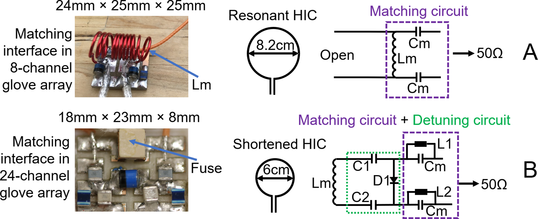
Left, from up to down: picture of matching circuit of the original 8-channel glove array, and picture of the matching circuit and detuning circuit on the 24-channel glove array; Right: A, schematic drawing of the resonant coil element and matching circuit of the original 8-channel glove array; B, schematic drawing of the shortened coil element, matching circuit and detuning circuit of the 24-channel glove array.
Glove array manufacturing
The purpose-built glove consists out of an inner glove that holds the electronics and an outer glove that protects the components. Figure 2a shows an exploded view of the inner glove with 24 coil elements. The inner glove consists of four main structures: palm, fingers, wrist, and a flap that rolls over on top. The four structures were designed to cover the entire hand and wrist. Each structure was constructed out of three layers: a layer of neoprene scuba (Mood Fabric, PN: 311533) in the middle as the main sculpting material which performs well in stretching and recovering, to maintain the flexibility of the coil; a layer of ESD flame resistant fabric (Asiatic Fiber Corp. PN: HR03) on the bottom, for patient safety; and a layer of mesh fabric (Mood Fabric, PN: 329659) on the top, which was used to organize the cables that connected the coil elements to their corresponding matching interface and to the remote preamplifier interface box. Lightweight and flexible micro-coaxial cable (diameter of outer diameter is 1.0mm, characteristic impedance is 50 ohms, customized and provided by Siemens) HIC elements were inserted into dedicated tubes. The tubes for the 5 coil elements on the fingers where integrated in the finger structure, the other tubes were sewed on the circumference of individual round-shaped patches (made of the ESD material and 6.0cm in diameter), and then the individual patches were sewed to the other three structures. Unlike the conventional array in which the overlap between the coil elements could be adjusted to achieve geometrical decoupling (32), the overlap between the HIC elements is hard to adjust after they were sewn on the structures. Therefore, the geometrical decoupling was deprioritized in the design. With the guidance of the SNR profile of 3-HIC elements with different overlap (31), one HIC was sewed on each finger, and 19 HIC elements (the maximal number of receive coil elements supported by one plug in Siemens Prisma/Skyra system is 24) were squeezed on the structures of palm, wrist and flap, with an overlap ideally not surpassing 35% of diameter. The finished HIC element layout is shown in Figure 2b. The fingers and thumb had 5 elliptical loops following the contour of fingers, the wrist and palm were covered with 17 circular loops with 6 cm diameter, and 2 irregular-shaped loops with the same circumference of the circular loops to cover gaps between structures. Although the overlap of the HIC elements on the palm, wrist and flap structures were well controlled less than 35% of diameter of the coil elements, the overlap between the coil elements on the flap structure and other three structures varied from −2mm (gap) to 45mm (two coil elements were almost stacked entirely one on other) when the hand is in a natural posture. Moreover, the position of the flap shifts with different hand postures, therefore changing the overlap between coil elements. All the HIC elements were sewn on before tuning and matching them on workbench. While tuning and matching one HIC element, the two ends of inner conductor of all other HIC elements were shortened with copper wire to mimic the preamp decoupling effect. The tuning of the coil element was adjusted by cutting the micro-coax cable length and the matching was adjusted by changing the two matching capacitors (Cm), when loaded with a hand-shaped phantom. To minimize the size of PCB, fixed capacitors rather than variable capacitors were used for matching. Please note that in contrast to the preamplifier decoupling in the conventional coil which creates an open circuit in the coil, the preamplifier decoupling of the HIC needs to create a short between the two ends of the inner conductor to destroy the resonant structure.
Figure 2.
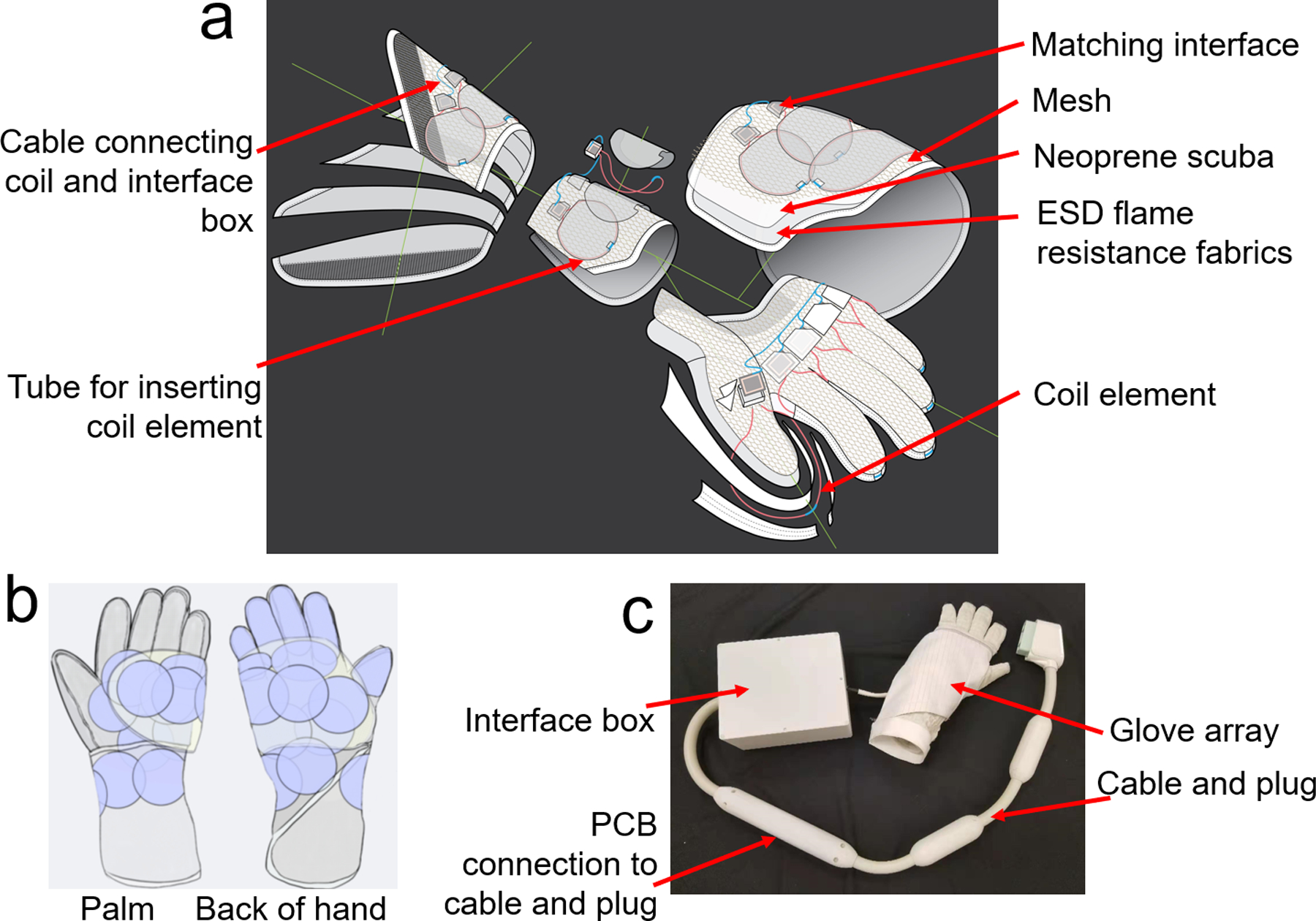
a) exploded view of the inner glove of the 24-channel glove array, it consists of four main structures: palm, fingers, wrist, and a flap that rolls over on top; b) picture of the assembled 24-channel glove array; c) coil layout of the 24-channel glove array.
Bench measurements
Both ends of the coil elements as well as the microcoax connecting the matching interface to the preamplifiers (Siemens Healthcare) were hot glued on the 3D-printed matching interface housing. The preamplifiers were considered too bulky to install directly onto the coils and were therefore housed remotely. The output from the matching interface was connected to the preamplifiers via microcoax. The 24 connecting microcoax cables were bundled into a corrugated hose at the wrist end of the inner glove to insulate the cables from the subject. Depending on the distance between the respective coil elements and the preamp interface box, the length of these 24 connecting microcoax cables varied. Lumped phase shifters were implemented in front of each preamplifier to achieve preamplifier decoupling for all the coil elements, and a shielded cable trap was added in front of each phase shifter to suppress shield currents. An outer glove was used to cover the exposed electronics. The outer glove was made of pleats (Mood Fabric, PN: 121786) covering the fingers to allow movement and neoprene scuba covering the palm and wrist, and it is big enough to not constrain the movement of the connecting microcoax cables.
Active detuning current suppression was measured for an unloaded coil element as the change in S21 with a double pick-up probe with and without bias applied to the PIN diode. Similarly, the achieved degree of preamplifier decoupling was measured for an unloaded coil element as the change in S21 detected by a double pickup probe when the coil was terminated with a 50ohm load, and when the preamplifier was powered to achieve the decoupling condition. Quality (Q) factor, measured as the ratio of the resonant frequency to bandwidth at −3 dB, was assessed by S21 measurements with a double-pickup probe lightly coupled into one coil. The unloaded Q was measured with the coil empty. The loaded Q was measured with the coil placed on a large rectangular phantom whose relative permittivity is 80 and conductivity 0.5S/m.
Scanner connection
Siemens Tim 4G technology was used to connect all 24 coil elements to the scanner through a single plug to streamline the workflow. All the preamplifier output lines were bundled together with DC bias lines into a single cable (length = 200 mm) affixed with one floating cable trap to suppress common mode currents at 123.2 MHz. Through a PCB connector, the cable was connected to a manufactured Siemens plug and cable with two inline cable traps (Siemens Healthcare, Erlangen, Germany), as shown in Figure 2c.
In vivo imaging
In vivo imaging and SNR measurements were performed upon approval by New York University Grossman School of Medicine Institutional Review Board and with informed written consent from the volunteers. The SNR of the new glove array was compared to a commercially available rigid 16-channel hand/wrist array (Hand/Wrist 16, Siemens Healthcare, Erlangen, Germany) with the hand and fingers in the flat, straightened posture. In addition, the SNR of the fingers in a curved posture was measured, which cannot be done with the 16-channel hand/wrist array. SNR maps were reconstructed with optimal coil combination from gradient echo (GRE) sequences with and without RF excitation (384mm×384mm FOV, 512×512 matrix, 200 ms TR, 4.92ms TE, 5mm Slice thickness, 5° flip angle). Data analysis was performed offline with custom software written in Matlab (The MathWorks, Natick, MA). The noise covariance matrix was calculated from the statistics of the noise samples scaled by dividing the sample covariance matrix by the scalar-valued noise equivalent bandwidth to account for noise autocorrelations within each channel due to the filtering introduced by the data acquisition electronics and receiver (33). Receive sensitivity profiles estimates were obtained by dividing individual coil images by the square root of the sum-of-squares combination of all coils, which is a good approximation for encircling arrays. With calculated coil sensitivity estimates and channel noise covariance estimates, composite images in absolute SNR units were obtained following the general procedure outlined by Kellman and McVeigh (33). The noise correlation matrix was computed from the noise covariance matrix in each case, and the mean and maximum values of its off-diagonal elements were recorded. Maps of the inverse g-factor (3) were calculated by decimating fully sampled k-space data of the in vivo SNR data for various acceleration factors using in-house software (34).
Sagittal and coronal proton density-weighted (PDw) images were acquired in a 29-year old male subject with the hand in natural posture and the hand in wrist extension posture by using a 2D FLASH sequence with the following parameters: TR = 3500 ms, TE = 33 ms, FOV = 60 mm × 80 mm, voxel resolution = 0.25 mm × 0.25 mm × 2 mm, GRAPPA = 2, flip angle = 120°, and time of acquisition (TA) = 1 min 55 s. Sagittal T2-weighted (T2w) images were acquired in a 31-year old female by using a 2D turbo spin echo (TSE) sequence with the following parameters: TR = 400 ms, TE = 15 ms, FOV = 300 mm × 93 mm, voxel resolution = 0.29 mm × 0.29 mm × 1.1 mm, GRAPPA = 2, Turbo factor = 3, excitation angle = 90°, refocusing angle = 180°, and TA = 1 min 34 s. All scans were performed on a MAGNETOM Prisma 3T MRI system (Siemens Healthcare, Erlangen, Germany).
Results:
Bench measurements
Active detuning during RF transmission provided −53 dB of isolation between the tuned and detuned receive-only elements. The Q-ratio (unloaded/loaded) of a single circular coil element on the flat phantom was 3.41 (75/22), and the irregular coil 2.71 (57/21). The degree of preamplifier decoupling was −26.4dB.
In vivo imaging
The coronal in vivo SNR maps of the 24-channel glove array demonstrated the desired large z-coverage in the hand and wrist. Compared to the 16-channel hand/wrist array, the 24-channel glove array had higher average SNR gain in the fingers, comparable SNR on the palm, and higher average SNR in the wrist. Specifically, we can see from the zoomed-in image in the finger from tip to knuckle region of interest (ROI) in the white rectangular block that the 24-channel glove array had more than 50% higher average SNR gain in the coronal plane while about 20% higher average SNR in the sagittal plane at the proximal interphalangeal joint and metacarpophalangeal joint, compared with the 16-channel hand/wrist array. In the curved posture with the 24-channel glove array, there was no significant SNR change in the wrist, but the average SNR in the white box dropped to 50.6% of that of the same coil in the case that the fingers stay flat, as we can see from Figure 3.
Figure 3.
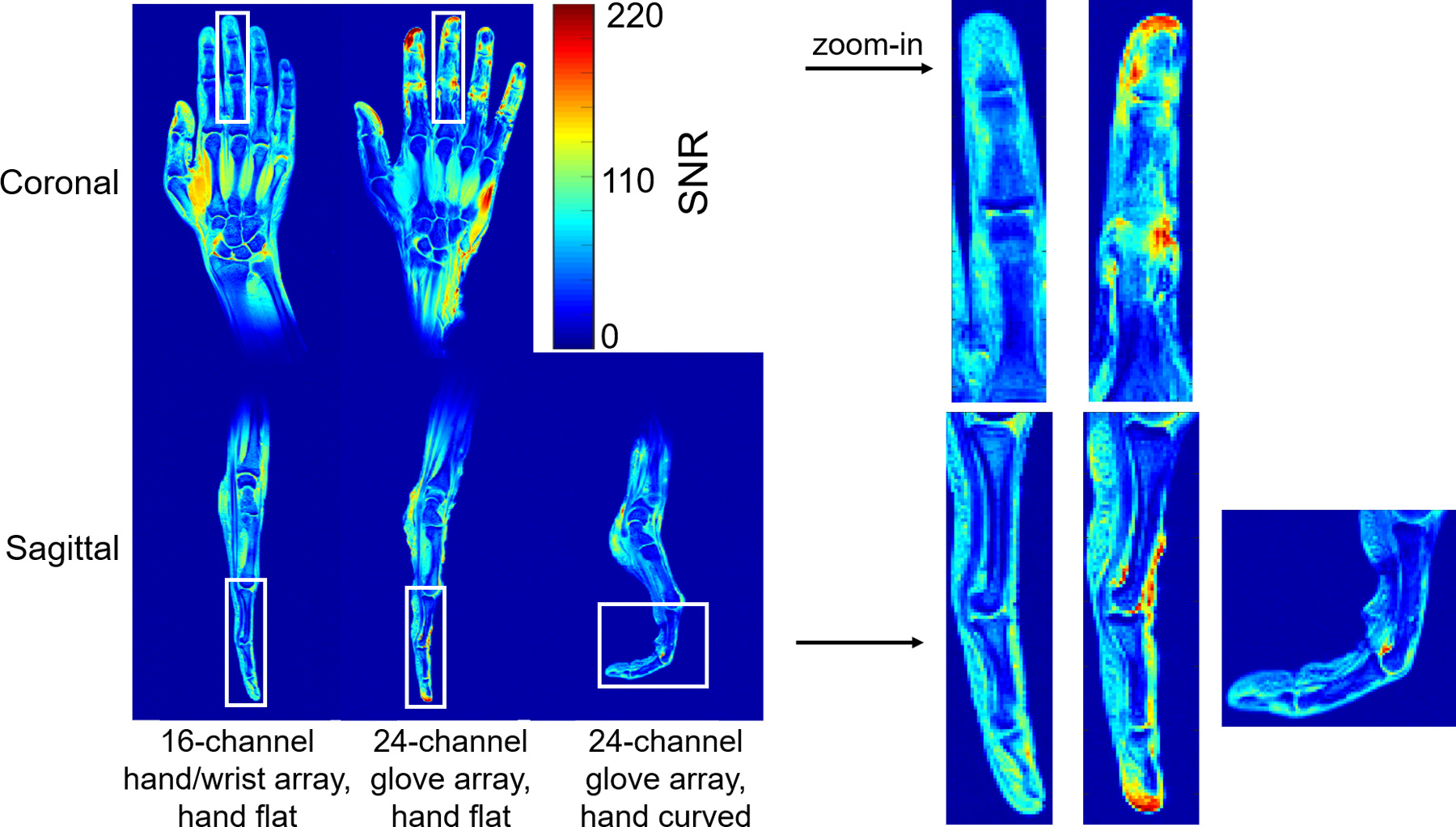
Coronal and sagittal in vivo SNR map of the 16-channel hand/wrist array and the 24-channel glove array when the hand was flat, and sagittal in vivo SNR map of the 24-channel glove array when the hand was curved. The high signal at the tip of the index finger is due to the swelling on the volunteer’s index finger (pre-existing condition). The SNR maps in the white box were zoomed in and plotted on the right.
Noise correlation matrixes of the 16-channel hand/wrist array and 24-channel glove array in the straight posture are shown in Figure 4; the median off-diagonal noise correlation was 0.132 and maximum of 0.431 for the 16-channel hand/wrist array, the median of 0.100 and the maximum of 0.386 for the 24-channel glove array. When the hand was curved, 24-channel glove array showed a median of 0.099 and the maximum of 0.4389, similar to the flat position.
Figure 4.
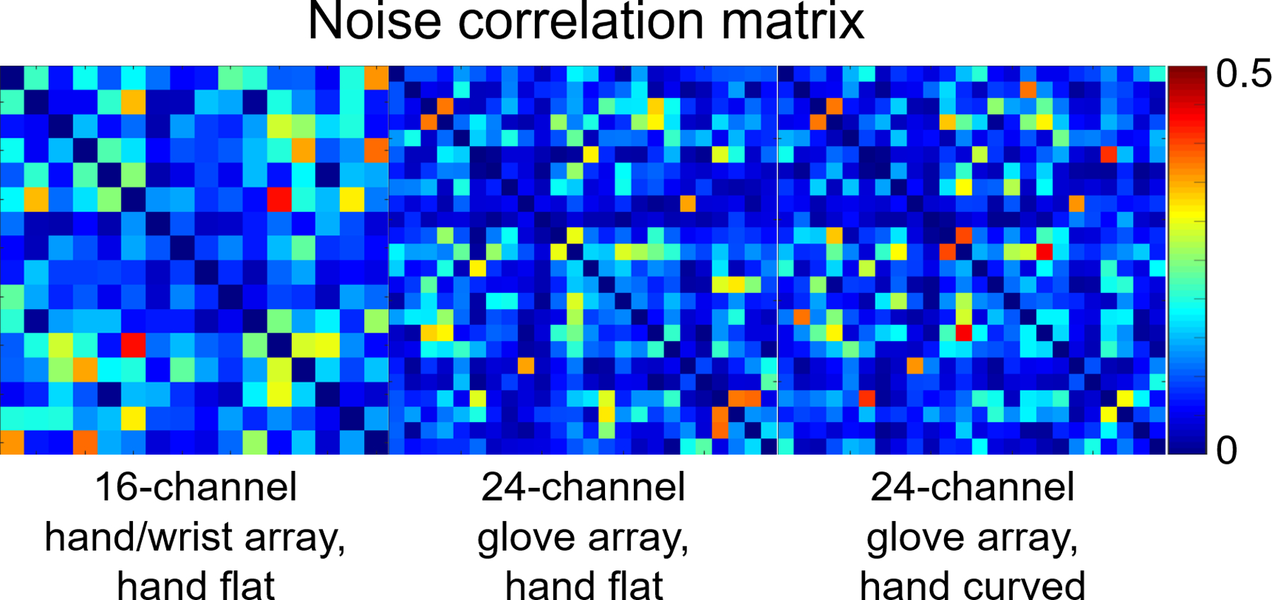
Noise correlation matrixes of the 16-channel hand/wrist array and the 24-channel glove array when the hand was flat, and the noise correlation matrix of the 24-channel glove array when the hand was curved.
Figure 5 shows the inverse g-factor results for the 24-channel glove array for 1D and 2D accelerations in the directions indicated by the arrows on the left column. The 24-channel glove array shows excellent acceleration performance in both directions. Acceleration by a factor of 3×3 entailed very little noise amplification. Acceleration performance in the thumb-pinky direction (up-down arrow) was overall better than that in the finger-wrist direction (left-right arrow).
Figure 5.
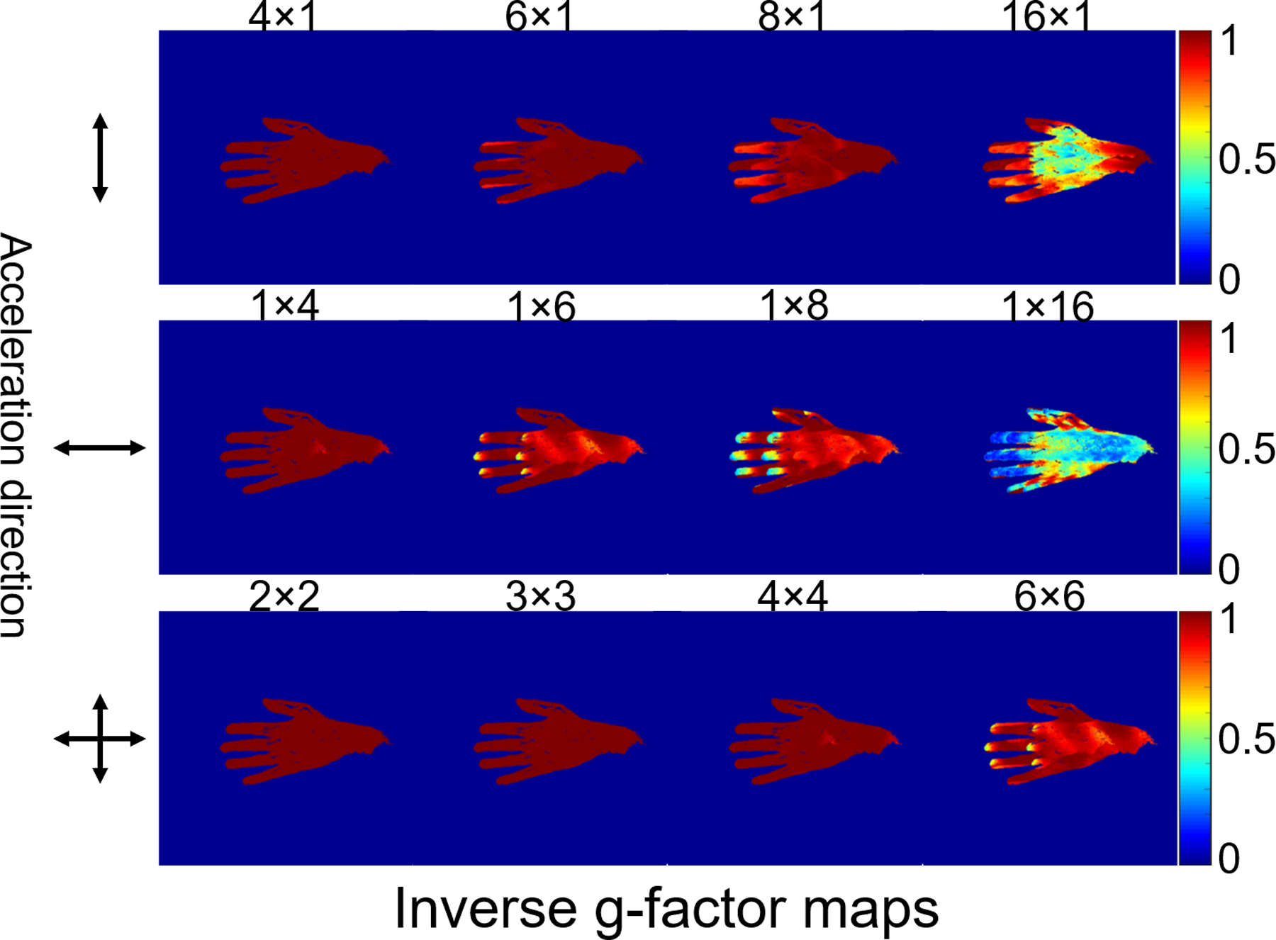
Maps of the inverse g-factor (1/g) of the 24-channel glove array for various one-dimensional and two-dimensional acceleration factors (shown above each map).
High-resolution (0.25 mm in-plane) coronal and sagittal PDw images of the wrist (Figure 6) demonstrate excellent anatomical image quality of the wrist when the hand was in natural posture and pencil grip posture. The flexibility of the 24-channel glove array allowed imaging the deformation of the anatomical structures in these different postures. In high-resolution (0.29 mm2 in-plane) TSE images of the hand, we were able to observe how the anatomical structure deforms when the hand changes from staying flat to being curved (Figure 7).
Figure 6.
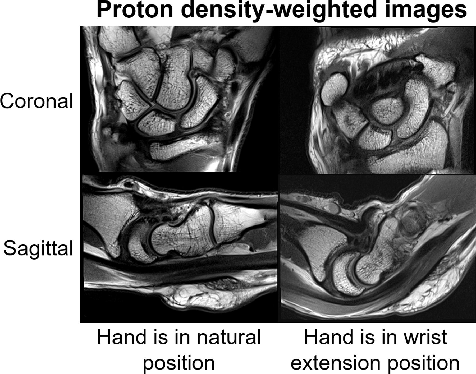
29-year-old male volunteer. Sagittal and coronal proton density-weighted (PDw) images (TR3500, TE33, Matrix 320 × 192, 2mm) acquired using the 24-channel glove array with the hand in the neutral position (left) as well as in the wrist extension posture (right).
Figure 7.
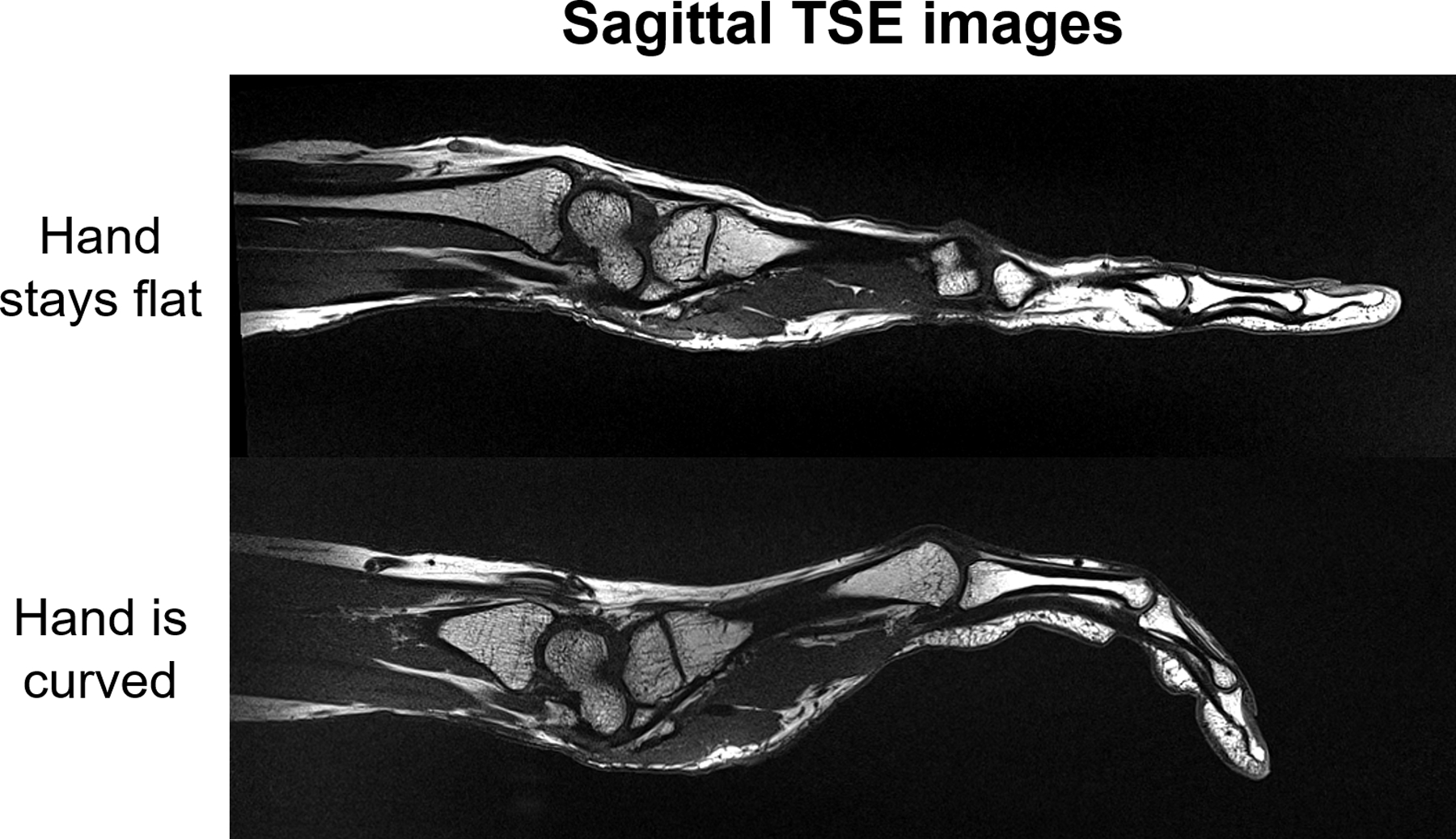
31-year-old female volunteer. Sagittal TSE images of hand were acquired with the 24-channel glove array when the hand stays flat and is curved respectively.
Discussion
A flexible 24-channel high impedance glove array for 3T MRI scanners was presented. In contrast to our original proof-of-concept 8-channel glove array (22), the 24-channel glove array provides additional safety features, and a housing that is more practical for frequent use. The outer glove can be removed and cleaned. However, for hygienic purposes, a disposable glove needs to be provided for the subject to put on before inserting their hand into the glove array.
The 24-channel glove array has sufficient coverage of both hand and wrist while also remaining flexible enough to allow dynamic imaging, including clinically relevant postures such as pencil grip and wrist flexion. Although the overlap between HIC elements varies from one posture to the next, the median value of the off-diagonal elements in the noise correlation matrixes remains almost the same when the hand is flat or curved, as shown in Figure 4. However, the SNR is lower in the curved palm and fingers, compared to the case when the hand is flat. This may be because the magnetic field of the curved coil elements is different from that of flat coil elements. Moreover, the coil was tuned and matched when the hand was in the natural posture on workbench and it was designed to maximize SNR in the natural posture. The resonant frequency of the coil elements shifts slightly when curved (31), which could cause SNR drop in the finger when the hand was curved. The signal inhomogeneity on the side of the hand could be related to the orientation of the HIC elements relative to the B0 field during the scan. Although the hand and wrist can move freely in the glove, its performance in different postures is expected to vary according to the coil orientation with respect to B0. The operator must carefully consider the desired posture in order to maximize coil transverse field while maintaining patient comfort.
The SNR maps and noise correlation matrixes of 3 subjects shown in Figure S4 demonstrated robust performance of the 24-channel glove array on different subjects. Although the noise correlation matrix showed that the coupling between the coil elements is small, we do see coupling between the coil elements in the individual sensitivity maps (Figure S5), which may be due to the 4G setup which mixes signals from two coil elements into one channel.
However, we observe that signal is more inhomogeneous for the 24-channel glove array than the 16-channel hand/wrist array. For example, since there is only one HIC element surrounding each finger in the coronal plane, we see image inhomogeneity in the sagittal plane of the finger, with much higher signal at the fingertip where the coil is passing through (both in Figure 3 and Figure 7). This image inhomogeneity becomes even worse on the thumb when the subject’s hand is small and coil element is not close-fitting on the outside anymore, as shown in Figure 3. Further optimization of coil placement should be made to improve the signal homogeneity. For example, by adding another coil element in each finger in the sagittal plane and adopt a more elastic fabric in the thumb area to ensure a snug fit. In addition, the homogeneity of the signal intensities can be improved using the body coil as a reference to normalize the signal(35).
The cable connecting the matching interface and the preamplifier interface in the 24-channel glove was kept relatively short such that no additional cable traps would be needed on the cable itself. Although the cable is long enough to allow the wrist and hand to move, the forearm and elbow must remain fixed, preventing motions such as dart throwers (36). To allow such large motions, the cable ideally should be longer, in which case additional cable traps are needed to block common-mode currents on the cable. To prevent bulky cable traps from interfering with the motion, flexible cable traps, such as the recently proposed “caterpillar” cable trap (37), could be used.
Previous experiments showed that the inductors Lm on different matching interfaces can couple with each other when the matching interfaces get close to each other. In the 24-channel glove array, the diameter of the HIC element was reduced from 82mm to 60mm to remove the bulky Lm from the matching interface and eliminate potential coupling between Lm. Simulations showed that the surface current distribution on the inner and outer conductors of the resonant coil element and the shortened one is almost the same (Figure S1). The only difference is that the surface current at the two ends of the inner conductor of the resonant coil element is zero, while in the shortened one it not. Therefore, the removal of the bulky Lm does not significantly change the coupling behavior of the coil itself. After shortening the HIC, the SNR is individual coil element slightly drops on the far end while boost a lot in peripheral area, as shown in Figure S2.
In general, the ideal size of the coil elements should be chosen after considering signal penetration and acceleration. For applications such as body imaging wherein large coil diameter is needed or at ultra-high field where the resonant HIC size is already quite small, a reduction in coil-size to eliminate Lm may not be acceptable. In fact, one may prefer to enlarge the coil. For those applications, coaxial coils with multiple gaps could be a solution (20). Alternatively, shielded-coaxial-cable (SCC) coil elements, which works at a higher mode of the transmission line, could be used to help enlarge the coil diameter (18,19).
As the HIC elements can be more robust against coupling compared to standard coils (31), we did not deliberately adjust the overlap between the coil elements to make the adjacent coil elements geometrically decoupled in the 24-channel glove array. Therefore, S21 between the HIC elements was not checked on workbench. This significantly reduced the time effort needed to test the HIC elements on workbench, when compared to conventional dense receive array designs. However, since we use two fixed capacitors for matching to reduce the size of the matching interface, the two capacitors need to be replaced every time of adjusting its capacitance for matching, which is a little bit tedious. Moreover, due to the discretion of capacitance values of the fixed capacitors, it is hard to manage the S11 of all coil elements lower than −20dB. The S11 of individual coil elements are shown in Figure S3.
Although the geometrical decoupling method was not used to decouple the HIC elements, overlapping between the HIC elements was needed in order to have continuous signal coverage in the ROI, as we found a signal null in the knuckle area of an trial version of the 24-channel glove array (38).
Since the HIC has inner and outer conductors, the conductive loss of the HIC is generally higher than a well build conventional coil. Therefore, the 6cm diameter HIC has a lower Q ratio (3.41) than a conventional coil element (7 for a 6cm diameter loop in (39). Based on Equation 1 in (7), the coil efficiency is 0.84 for the shortened HIC and 0.92 for the conventional coil, thus 8.7% lower for a single coil element. However, due to the close-fitting of the HIC, the SNR of the 24-channel glove array is higher than the commercial 16-channel hand/wrist array in the fingers when the hand stays flat.
MRI of the wrist is commonly performed for clinical evaluation of the triangular fibrocartilage complex (TFCC), major interosseous ligaments (e.g. scapholunate and lunotriquetral interosseous ligaments) and cartilaginous articular surfaces (40). The TFCC is small with complex anatomy and the intrinsic interosseous ligaments are similarly small structures requiring optimal MRI quality for accurate assessment. Although less commonly performed nowadays due to improved MRI quality, some surgeons still prefer MR arthrograms for the assessment of the TFCC and intrinsic ligaments (41). This subjects the patient to the additional step of image-guided injection and associated risks. In this regard, the 24-channel glove array and improved resolution of the small carpal structures compared to standard wrist coils may circumvent the need for intra-articular injection. Therefore, the combined flexibility of the 24-channel glove array coil allowing for greater range of motion at the wrist and high-resolution imaging capability may potentially provide a powerful tool for acquiring both improved anatomic detail and kinematic information to aid clinical management.
Conclusion
In conclusion, a purpose built 3T glove array that embeds 24 HIC elements for coverage of both hand and wrist is demonstrated. The 24-channel glove array allows a great range of motion at both the wrist and hand.
Supplementary Material
Figure S1. Modeling of a resonant 8.2cm diameter HIC coil (a) and a shortened 6cm diameter HIC coil (b) loaded with a 20cm×20cm×20cm cubic phantom (ɛr=60, σ=0.45 S/m); and Smith chart of the resonant HIC (c) and the shortened HIC (d) respectively. The surface current distributions on the outer surface of the inner and outer conductors of the resonant HIC and the shortened HIC were plotted in S1e, S1f, S1g and S1h respectively.
Figure S2. SNR maps of the resonant HIC (a) and the shortened HIC (b), and the ratio between them (c and d).
Figure S3. S11 of the 24 coil elements, when loaded with the hand of a volunteer subject.
Figure S4. SNR of 3 subjects in sagittal and coronal planes and the noise correlation matrixes correspondingly.
Figure S5. Coil placement on the inner glove and sensitivity maps of individual coil elements.
Acknowledgement
The authors very much appreciate mechanical engineer Jerzy Walczyk for designing the 3D CAD models of the PCB connection housing and preamplifier interface housing, and MRI specialist Mohammed Ahmed for in vivo data acquisition.
FUNDING INFORMATION:
National Institutes of Health, Grant/Award Numbers:
NIH P41 EB017183, NIH R01 EB024536
Cancer Prevention and Research Institute of Texas, Grant Number: RR180056
Footnotes
Conflict of Interest
Markus Vester and Robert Rehner are employed by Siemens Healthcare AG, Erlangen.
Reference
- 1.Roemer PB, Edelstein WA, Hayes CE, Souza SP, Mueller OM. The NMR phased array. Magn Reson Med 1990;16(2):192–225. [DOI] [PubMed] [Google Scholar]
- 2.Sodickson DK, Manning WJ. Simultaneous acquisition of spatial harmonics (SMASH): fast imaging with radiofrequency coil arrays. Magn Reson Med 1997;38(4):591–603. [DOI] [PubMed] [Google Scholar]
- 3.Pruessmann KP, Weiger M, Scheidegger MB, Boesiger P. SENSE: sensitivity encoding for fast MRI. Magn Reson Med 1999;42(5):952–962. [PubMed] [Google Scholar]
- 4.Griswold MA, Jakob PM, Chen Q, Goldfarb JW, Manning WJ, Edelman RR, Sodickson DK. Resolution enhancement in single-shot imaging using simultaneous acquisition of spatial harmonics (SMASH). Magn Reson Med 1999;41(6):1236–1245. [DOI] [PubMed] [Google Scholar]
- 5.Nordmeyer-Massner JA, De Zanche N, Pruessmann KP. Stretchable coil arrays: application to knee imaging under varying flexion angles. Magn Reson Med 2012;67(3):872–879. [DOI] [PubMed] [Google Scholar]
- 6.Corea JR, Flynn AM, Lechene B, Scott G, Reed GD, Shin PJ, Lustig M, Arias AC. Screen-printed flexible MRI receive coils. Nat Commun 2016;7:10839. [DOI] [PMC free article] [PubMed] [Google Scholar]
- 7.Corea JR, Lechene PB, Lustig M, Arias AC. Materials and methods for higher performance screen-printed flexible MRI receive coils. Magn Reson Med 2017;78(2):775–783. [DOI] [PMC free article] [PubMed] [Google Scholar]
- 8.Port A, Reber J, Vogt C, Marjanovic J, Sporrer B, Wu L, Mehmann A, Brunner DO, Burger T, Troester G, Huang Q, Pruessmann KP. Towards wearable MR detection: A stretchable wrist array with on-body digitization. Proc Int Soc Magn Reson Med 26 (2018) 2018:1. [Google Scholar]
- 9.Vasanawala SS, Stormont R, Lindsay S, Grafendorfer T, Cheng JY, Pauly JM, Lustig M, Scott G, Guzman JX, Taracila V, Chirayath D, Robb F. Development and Clinical Implementation of Very Light Weight and Highly Flexible AIR Technology Arrays. Proc Int Soc Magn Reson Med 25 (2017):p.755. [Google Scholar]
- 10.Port A, Luechinger R, Albisetti L, Varga M, Marjanovic J, Reber J, Brunner DO, Pruessmann KP. Detector clothes for MRI: A wearable array receiver based on liquid metal in elastic tubes. Sci Rep 2020;10(1):8844. [DOI] [PMC free article] [PubMed] [Google Scholar]
- 11.Mehmann A, Varga M, Vogt C, Port A, Reber J, Marjanovic J, Pruessmann KP, Troster G. On the Bending and Stretching of Liquid Metal Receive Coils for Magnetic Resonance Imaging. IEEE Trans Biomed Eng 2019;66(6):1542–1548. [DOI] [PubMed] [Google Scholar]
- 12.Vincent JM, Rispoli JV. Conductive Thread-Based Stretchable and Flexible Radiofrequency Coils for Magnetic Resonance Imaging. IEEE Trans Biomed Eng 2020;67(8):2187–2193. [DOI] [PMC free article] [PubMed] [Google Scholar]
- 13.McGee KP, Stormont RS, Lindsay SA, Taracila V, Savitskij D, Robb F, Witte RJ, Kaufmann TJ, Huston J 3rd, Riederer SJ, Borisch EA, Rossman PJ. Characterization and evaluation of a flexible MRI receive coil array for radiation therapy MR treatment planning using highly decoupled RF circuits. Phys Med Biol 2018;63(8):08NT02. [DOI] [PubMed] [Google Scholar]
- 14.Wu B, Zhang X, Wang C, Li Y, Pang Y, Lu J, Xu D, Majumdar S, Nelson SJ, Vigneron DB. Flexible transceiver array for ultrahigh field human MR imaging. Magn Reson Med 2012;68(4):1332–1338. [DOI] [PMC free article] [PubMed] [Google Scholar]
- 15.Hosseinnezhadian S, Frass-Kriegl R, Goluch-Roat S, Pichler M, Sieg J, Vit M, Poirier-Quinot M, Darrasse L, Moser E, Ginefri JC, Laistler E. A flexible 12-channel transceiver array of transmission line resonators for 7T MRI. J Magn Reson 2018;296:47–59. [DOI] [PubMed] [Google Scholar]
- 16.Frass-Kriegl R, Laistler E, Hosseinnezhadian S, Schmid AI, Moser E, Poirier-Quinot M, Darrasse L, Ginefri JC. Multi-turn multi-gap transmission line resonators - Concept, design and first implementation at 4.7T and 7T. J Magn Reson 2016;273:65–72. [DOI] [PubMed] [Google Scholar]
- 17.Kriegl R, Ginefri JC, Poirier-Quinot M, Darrasse L, Goluch S, Kuehne A, Moser E, Laistler E. Novel inductive decoupling technique for flexible transceiver arrays of monolithic transmission line resonators. Magn Reson Med 2015;73(4):1669–1681. [DOI] [PubMed] [Google Scholar]
- 18.Ruytenberg T, Webb A, Zivkovic I. Shielded-coaxial-cable coils as receive and transceive array elements for 7T human MRI. Magn Reson Med 2020;83(3):1135–1146. [DOI] [PMC free article] [PubMed] [Google Scholar]
- 19.Ruytenberg T, Webb A, Zivkovic I. A flexible five-channel shielded-coaxial-cable (SCC) transceive neck coil for high-resolution carotid imaging at 7T. Magn Reson Med 2020;84(3):1672–1677. [DOI] [PMC free article] [PubMed] [Google Scholar]
- 20.Nohava L, Czerny R, Roat S, Obermann M, Kuehne A, Frass-Kriegl R, Felblinger J, Ginefri JC, Laistler E. Flexible Multi-Turn Multi-Gap Coaxial RF Coils: Design Concept and Implementation for Magnetic Resonance Imaging at 3 and 7 Tesla. IEEE Trans Med Imaging 2021;40(4):1267–1278. [DOI] [PubMed] [Google Scholar]
- 21.Mollaei M, Van Leeuwen C, Raaijmakers A, C. S. Analysis of High Impedance Coils Both in Transmission and Reception Regimes. IEEE Access 2020;8:129754–129762. [Google Scholar]
- 22.Zhang B, Sodickson DK, Cloos MA. A high-impedance detector-array glove for magnetic resonance imaging of the hand. Nat Biomed Eng 2018;2(8):570–577. [DOI] [PMC free article] [PubMed] [Google Scholar]
- 23.Libby LL. Special Aspects of Balanced Shielded Loops. in proceedings of the IRE, vol 34, no 9, pp 641–646 1946. [Google Scholar]
- 24.Shaw CB, Foster BH, Borgese M, Boutin RD, Bateni C, Boonsri P, Bayne CO, Szabo RM, Nayak KS, Chaudhari AJ. Real-time three-dimensional MRI for the assessment of dynamic carpal instability. PLoS One 2019;14(9):e0222704. [DOI] [PMC free article] [PubMed] [Google Scholar]
- 25.Abbas B, Fishbaugh J, Petchprapa C, Lattanzi R, Gerig G. Analysis of the kinematic motion of the wrist from 4D magnetic resonance imaging. Proc SPIE 10949, Medical Imaging 2019;109491E. [Google Scholar]
- 26.Henrichon SS, Foster BH, Shaw C, Bayne CO, Szabo RM, Chaudhari AJ, Boutin RD. Dynamic MRI of the wrist in less than 20 seconds: normal midcarpal motion and reader reliability. Skeletal Radiol 2020;49(2):241–248. [DOI] [PMC free article] [PubMed] [Google Scholar]
- 27.Kani KK, Mulcahy H, Chew FS. Understanding carpal instability: a radiographic perspective. Skeletal Radiol 2016;45(8):1031–1043. [DOI] [PubMed] [Google Scholar]
- 28.Kelly PM, Hopkins JG, Furey AJ, Squire DS. Dynamic CT Scan of the Normal Scapholunate Joint in a Clenched Fist and Radial and Ulnar Deviation. Hand (N Y) 2018;13(6):666–670. [DOI] [PMC free article] [PubMed] [Google Scholar]
- 29.Demehri S, Hafezi-Nejad N, Morelli JN, Thakur U, Lifchez SD, Means KR, Eng J, Shores JT. Scapholunate kinematics of asymptomatic wrists in comparison with symptomatic contralateral wrists using four-dimensional CT examinations: initial clinical experience. Skeletal Radiol 2016;45(4):437–446. [DOI] [PubMed] [Google Scholar]
- 30.Langner I, Fischer S, Eisenschenk A, Langner S. Cine MRI: a new approach to the diagnosis of scapholunate dissociation. Skeletal Radiol 2015;44(8):1103–1110. [DOI] [PubMed] [Google Scholar]
- 31.Zhang B, Sodickson DK, Cloos MA. A high-impedance detector-array glove for magnetic resonance imaging of the hand. Nat Biomed Eng 2018. [DOI] [PMC free article] [PubMed] [Google Scholar]
- 32.Wiggins GC, Polimeni JR, Potthast A, Schmitt M, Alagappan V, Wald LL. 96-Channel receive-only head coil for 3 Tesla: design optimization and evaluation. Magn Reson Med 2009;62(3):754–762. [DOI] [PMC free article] [PubMed] [Google Scholar]
- 33.Kellman P, McVeigh ER. Image reconstruction in SNR units: a general method for SNR measurement. Magn Reson Med 2005;54(6):1439–1447. [DOI] [PMC free article] [PubMed] [Google Scholar]
- 34.Montin E, Wiggins R, Block KT, Lattanzi R. MR Optimum – A web-based application for signal-to-noise ratio evaluation. Proc Int Soc Magn Reson Med 27 (2019):p.4617. [Google Scholar]
- 35.Brey WW, Narayana PA. Correction for intensity falloff in surface coil magnetic resonance imaging. Med Phys 1988;15(2):241–245. [DOI] [PubMed] [Google Scholar]
- 36.Edirisinghe Y, Troupis JM, Patel M, Smith J, Crossett M. Dynamic motion analysis of dart throwers motion visualized through computerized tomography and calculation of the axis of rotation. J Hand Surg Eur Vol 2014;39(4):364–372. [DOI] [PubMed] [Google Scholar]
- 37.Karasan E, Taracila V, Robb F, Lustig M. The Very RF Hungry Caterpillar Trap (Highly Flexible, Distributed System of Toroid Cable Traps). Proc Int Soc Magn Reson Med 28 (2020):p.4050. [DOI] [PMC free article] [PubMed] [Google Scholar]
- 38.Zhang B, Ho J, Hodono S, Wang B, Brown R, Lattanzi R, Vester M, Rehner R, Cloos MA. A 22-channel high impedance glove array for dynamic hand and wrist imaging at 3T. Proc Int Soc Magn Reson Med 28 (2020):p.753. [DOI] [PMC free article] [PubMed] [Google Scholar]
- 39.Wiggins GC, Triantafyllou C, Potthast A, Reykowski A, Nittka M, Wald LL. 32-channel 3 Tesla receive-only phased-array head coil with soccer-ball element geometry. Magn Reson Med 2006;56(1):216–223. [DOI] [PubMed] [Google Scholar]
- 40.Daunt N, Couzens GB, Cutbush K, Green J, Ross M. Accuracy of magnetic resonance imaging of the wrist for clinically important lesions of the major interosseous ligaments and triangular fibrocartilage complex; correlation with radiocarpal arthroscopy. Skeletal Radiol 2021. [DOI] [PubMed] [Google Scholar]
- 41.Cherian BS, Bhat AK, Rajagopal KV, Maddukuri SB, Paul D, Mathai NJ. Comparison of MRI & direct MR arthrography with arthroscopy in diagnosing ligament injuries of wrist. J Orthop 2020;19:203–207. [DOI] [PMC free article] [PubMed] [Google Scholar]
Associated Data
This section collects any data citations, data availability statements, or supplementary materials included in this article.
Supplementary Materials
Figure S1. Modeling of a resonant 8.2cm diameter HIC coil (a) and a shortened 6cm diameter HIC coil (b) loaded with a 20cm×20cm×20cm cubic phantom (ɛr=60, σ=0.45 S/m); and Smith chart of the resonant HIC (c) and the shortened HIC (d) respectively. The surface current distributions on the outer surface of the inner and outer conductors of the resonant HIC and the shortened HIC were plotted in S1e, S1f, S1g and S1h respectively.
Figure S2. SNR maps of the resonant HIC (a) and the shortened HIC (b), and the ratio between them (c and d).
Figure S3. S11 of the 24 coil elements, when loaded with the hand of a volunteer subject.
Figure S4. SNR of 3 subjects in sagittal and coronal planes and the noise correlation matrixes correspondingly.
Figure S5. Coil placement on the inner glove and sensitivity maps of individual coil elements.


