Abstract
Additively manufactured trabecular tantalum (Ta) scaffolds are promising bone repair materials for load-bearing applications due to their good pore interconnectivity. However, a thorough mechanical behavior evaluation is required before conducting animal studies and clinical research using these scaffolds. In this study, we revealed the compressive mechanical behavior and material failure mechanism of trabecular tantalum scaffolds by compression testing, finite element analysis (FEA), and scanning electron microscopy (SEM). Trabecular tantalum scaffolds with porosities of 65%, 75%, and 85% were fabricated by laser powder bed fusion-based additive manufacturing. Porosity has a significant effect on their compressive mechanical properties. As the porosity decreased from 85% to 65%, the compressive yield strength and elastic modulus increased from 11.9 MPa to 35.7 MPa and 1.1 GPa to 3.0 GPa, respectively. Compression testing results indicate that trabecular tantalum scaffolds demonstrate ductile deformation and excellent mechanical reliability. No macroscopic cracks were found when they were subjected to strain up to 50%. SEM observations showed that material failure results from tantalum strut deformation and fracture. Most microcracks occurred at conjunctions, whereas few of them appear on the struts. FEA-generated compressive stress distribution and material deformation were consistent with experimental results. Stress concentrates at strut conjunctions and vertical struts, where fractures occur during compression testing, indicating that the load-bearing capability of trabecular tantalum scaffolds can be enhanced by strengthening strut conjunctions and vertical struts. Therefore, additively manufactured trabecular tantalum scaffolds can be used in bone tissue reconstruction applications.
Keywords: Tantalum scaffold, Additive manufacturing, Bone repair, Compressive behavior, Finite element analysis, Material failure
1. Introduction
Porous tantalum (Ta) scaffolds have attracted immense interest in bone tissue engineering owing to their excellent physicochemical and biological properties, including outstanding corrosion resistance, excellent ductility, non-cytotoxicity, and superior bioactivity and biocompatibility[1-3]. Numerous biological studies in vitro and in vivo have confirmed that Ta scaffolds can effectively promote osteoblast adhesion, proliferation, differentiation, and mineralization, and have superior osteoconductivity, osteointegration, and vascularization[4-7]. Furthermore, the in vitro biological performance and in vivo bone ingrowth of Ta scaffolds are superior compared to those of Ti6Al4V scaffolds[8,9]. Therefore, porous Ta scaffolds are considered the promising third-generation bone repair materials. At present, major challenges in the development of porous Ta scaffolds are fabrication, structural design and optimization.
Ta processing is hampered by the high melting temperature of Ta (2996°C)[10]. Porous Ta scaffolds are typically fabricated by chemical vapor deposition (CVD), powder metallurgy (PM), and additive manufacturing (AM). In CVD, a Ta coating is deposited on a low-density vitreous carbon skeleton by a chemical reaction to prepare porous Ta scaffolds[11]. Since the CVD-fabricated porous Ta acetabular cup was introduced (Trabecular Metal™, Zimmer, Warsaw, IN, USA) in the early 2000s, commercially available CVD-fabricated porous Ta implants have been applied to bone defect repair and bone disease treatment with excellent clinical results[12-14]. However, this technique is complicated and expensive with poor control over the porous structure and outer geometry to fabricate patient-specific and anatomically matching implants. Using PM, porous Ta scaffolds are manufactured by removing space-holding materials through high-temperature sintering or dissolution[15-17]. However, PM-fabricated porous Ta scaffolds present closed or isolated pores, resulting in poor interconnectivity and osteointegration[2]. Compared with CVD and PM, AM is a more versatile and effective technology to customize porous bone implants with complicated geometries that match anatomical shapes and meet personalized treatment requirements. Laser powder bed fusion (LPBF), an AM technology, employs high-energy lasers to selectively melt the pre-laid metal powder on the build platform layer by layer according to a pre-designed CAD model to manufacture fully dense functional parts with complex geometries and well-designed open porous structures[18-20]. LPBF allows rapid fabrication of parts with complex geometries and relatively high mechanical performance directly from powders without the time-consuming mold design process[21,22]. Due to its high precision, LPBF has recently been used to fabricate Ta-based structures with controllable porosity/pore geometry and predictable mechanical properties. Wauthle et al.[5] applied LPBF to fabricated porous Ta scaffolds comprising of rhombic dodecahedron unit cells for the 1st time. Compression tests and biological evaluation suggested that these scaffolds exhibited desirable mechanical properties and enhanced osteogenesis and osteointegration. Wang et al.[7] fabricated porous Ta scaffolds with diamond unit cells by LPBF and achieved good osteointegration performance through animal experiments. Guo et al.[9] compared the biological performance of porous Ta scaffolds with that of porous Ti6Al4V scaffolds fabricated by LPBF and reported that porous Ta scaffolds showed better biocompatibility and osteointegration than porous Ti6Al4V scaffolds. Therefore, AM, especially LPBF-based AM, is expected to become the mainstream fabrication method for porous Ta scaffolds in the future.
The trabecular lattice is an irregular structure, which has attracted great interest in bone tissue engineering due to the similarity of its micro-architecture to that of a natural bone and good interconnectivity suitable for bone implants. Liu et al.[23] designed a trabecular bone structure derived from micro-computed tomography images of cancellous bone and fabricated trabecular porous titanium (Ti) scaffolds by LPBF, achieving a good match of morphological accuracy and mechanical properties to those of the natural bone. Wang et al.[24] constructed controllable irregular structures based on the Voronoi–Tessellation method and fabricated trabecular porous Ti6Al4V scaffolds with predictable porosity and mechanical behavior by LPBF. However, studies on trabecular porous Ta scaffolds fabricated by AM were rarely reported. In our laboratory, we have successfully fabricated trabecular porous Ta scaffolds using LPBF and investigated their pore structure characteristics and comprehensive mechanical properties[25]. However, mechanical behavior evaluation is required prior to their deployment in clinical research.
In this work, we used LPBF-based AM to fabricate innovative trabecular Ta scaffolds with various porosities (65%, 75%, and 85%). Morphological evaluation was conducted to analyze the microstructural characteristics of as-prepared samples. The mechanical behavior and material failure mechanism of AM trabecular Ta scaffolds were investigated by compression testing, finite element analysis (FEA), and microscopic observations.
2. Materials and methods
2.1. Design and manufacturing
A stochastic porous structure based on Voronoi tessellation was designed by the Grasshopper plug-in in Rhinoceros 6.0 (Robert McNeel and Associates, Seattle, WA, USA) and was saved in the STL format. First, we constructed a three-dimensional (3D) Voronoi diagram with randomly-distributed seed points. Then, the wireframe of the 3D Voronoi diagram was extracted. The trabecular porous structure can be constructed by employing the wireframe to form a circular strut with a cross-sectional diameter (D). The porosity of the trabecular scaffold can be adjusted by changing the number of seed points and the strut diameter. Indispensable repairs were conducted by Materialise Magics 24.0 (Materialise N.V., Leuven, Belgium) to create CAD models for further process. During the laser fusion process, the raw material powders at the boundaries of selected locations become fused or half fused, increasing the strut diameter beyond its designed value. In the same structure, the bigger the strut diameter, the smaller the pore size and porosity will be. By our many optimizations and attempts, a deviation of approximately 2% between the porosity of AM trabecular Ta scaffolds and the designed models was summarized. Therefore, to obtain Ta scaffolds with porosities of 65%, 75%, and 85%, cylindrical trabecular porous models with porosities of 67%, 77%, and 87%, having the same outer geometry (diameter × height: 10 mm × 10 mm) and strut diameter (250 μm), were designed, as shown in Figure 1.
Figure 1.
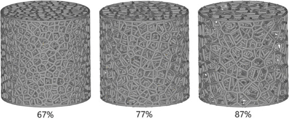
Designed models of trabecular porous Ta scaffolds with nominal porosities of 67%, 77%, and 87%.
Fully dense pure Ta spherical powder with a particle size range of 15 μm and 45 μm (TEKNA Advanced Materials Inc., Sherbrooke, QC, Canada) was used to fabricate trabecular Ta scaffolds. The powder microstructure and characteristics have been described in our previous work[25]. Based on CAD data, samples were manufactured by Dazhou Medical Co., Ltd. (Shenzhen, Guangdong, China) using Farsoon FS271M (Farsoon Technologies Co., Ltd., Changsha, Hunan, China), an LPBF-based AM system equipped with a 500W Yb: YAG fiber laser with a spot size of 80 μm. The production step was performed in an argon environment with <0.05% oxygen to prevent oxidation. The process parameters and scanning strategy have significant effect on the microstructures and properties of LPBF parts[26,27]. We employed the optimized processing parameters, including laser power, scan speed, fill distance, and layer thickness, in the fabrication of dense samples to manufacture porous Ta scaffolds with relatively dense Ta struts. An optimized scanning strategy was employed to reduce the residual stress produced during laser fusion process. After the fabrication, specimens were removed from the substrate using numerical control wire electrical discharge cutter DK7732 (Changde Machinery Manufacturing Co., Ltd., Taizhou, Jiangsu, China). The unfused Ta powders adhered to the sample surface were removed by sandblasting (Blaster 9060A, Hexin Sandblasting Equipment Co., Ltd., Shenzhen, Guangdong, China). Then, as-prepared samples were subjected to annealing (Vacuum Annealing Furnace SLZK1100-45, Litan New Energy Development Co., Ltd., Suzhou, Jiangsu, China) for releasing residual thermal stress generated during the fabrication process. The annealing procedures were conducted in a vacuum atmosphere. First, the temperature rose at a rate of 5°C/min to 300°C and held for 30 min, and then rose at the same rate to the plateau annealing temperature of 1000°C and held for 120 min before dropped to room temperature. Finally, all specimens were ultrasonically and separately cleaned for 30 min in distilled water and ethanol. Ten samples of each model were fabricated.
2.2. Morphological analysis
The strut diameters and average pore sizes of as-prepared samples were measured from the optical micrographs with n = 10 for each porosity. Their overall porosities were determined by the dry weighing method under normal atmosphere conditions with n = 10 for each porosity. Sample dimensions were measured by digital Vernier calipers 111-101-10G with an accuracy of 0.01 mm (Digital Measurement and Control Co., Ltd., Guilin, Guangxi, China) and derived from the average of 3 measurements for each specimen. The dry weights of as-fabricated samples were measured using an electronic densimeter with a sensitivity of 0.0001 g (DK-120MD, Decca Precision Instrument Co., Ltd., Shenzhen, Guangdong, China) at room temperature (25°C). Relative density was calculated by dividing the actual weight (W1) by the theoretical weight (W2) of the macrovolume using a theoretical density (16.6 g/cm2) of pure Ta. The porosity of scaffolds was obtained using the formula as follows:

The microstructural characteristics of AM-fabricated porous Ta scaffolds were visualized using hot field emission scanning electron microscopy (FESEM) (MERLIN Compact, Carl Zeiss Inc., Oberkochen, Germany) equipped with energy-dispersive X-ray spectroscopy (EDS), which was used to ascertain the chemical compositions of the samples.
2.3. Mechanical testing
To evaluate the mechanical properties of AM-fabricated cylindrical trabecular Ta scaffolds (f10 mm × H10 mm), 6 samples (n = 6) from each group (65%, 75%, and 85%) were subjected to uniaxial static compression testing at room temperature (25°C). Compression tests were performed in accordance with ISO 13314:2011 (mechanical testing of metals-ductility testing-compression test for porous and cellular metals) using mechanical testing machine (max. 5 kN, Instron 4301, Instron Company, Norwood, MA, USA) equipped with an extensometer (YSJ50/5-ZC, Suzhou Shenghui Precision Instrument Technology Co., Ltd., Suzhou, Jiangsu, China). A constant deformation rate of 0.5 mm/min was applied during compression tests. Each specimen was compressed to 50% strain to obtain stress–strain curves. The elastic modulus (E) as the gradient of the straight line was calculated from the linear deformation region at the beginning of the compressive stress–strain curve. The compressive 0.2% offset stress was identified from the stress–strain curve as the yield strength (σy).
2.4. Experimental study of compressive behavior and material failure
(1) Static compression testing
To obtain the initial stages of trabecular Ta scaffolds after collapse under static compressive loading, 10%, 15%, and 20% strain were set for specimens with 65%, 75%, and 85% porosities, respectively. Two specimens of each porosity (annealed and unannealed) were prepared for compression tests with an identical strain. Compression tests were performed under the same equipment and deformation rate as mechanical tests described above. Post-compressive microstructures of all samples were observed by hot FESEM (MERLIN Compact, Carl Zeiss Inc., Oberkochen, Germany) before metallographic sample preparation.
(2) Metallographic sample preparation
Post-compressive AM trabecular Ta scaffolds were prepared to metallographic specimens through the vacuum pressure impregnation resin (VPIR) method[28]. Twenty gram of acrylic powder (G90500, Gaopin Precision Instrument Co., Ltd., Kunshan, Jiangsu, China) and 40 ml liquid hardener (G90400, Gaopin Precision Instrument Co., Ltd., Kunshan, Jiangsu, China) were mixed and stirred uniformly at room temperature (25°C). Metallographic inlay molds (φ20 mm × H20 mm) were used to prepare metallographic specimens. Vacuum defoaming (SIE-MIX80, SIENOX Co., Ltd., Guangzhou, Guangdong, China) was employed to exhaust the air that remained in porous Ta scaffolds, making the resin solution fully infiltrate into the pores of scaffolds. Then, the metallographic specimens were placed at room temperature for 12 h to complete resin solidification. In addition, an uncompressed porous Ta metallographic sample was prepared for each porosity as the control group.
(3) Grinding and polishing
Grinding and polishing of as-prepared metallographic specimens were conducted by a metallographic sample grinding and polishing machine (YMP-2B, Metallurgical Equipment Co., Ltd., Shanghai, China) with a sandpaper diameter of 230 mm. Metallographic specimens were ground using 100, 200, 400, 800, 1200, 1500, and 2000 SiC papers and then polished by diamond suspensions with sizes of 5, 2, and 0.5 μm. To achieve the same polished cross section, 3 metallographic specimens of each porosity were ground under an identical extent and direction. The schematic of porous Ta metallographic sample preparation is presented in Figure 2. The morphological characterizations of the metallographic specimens were observed by electron backscattered diffraction (EBSD, Carl Zeiss Inc., Oberkochen, Germany).
Figure 2.

Schematic of porous Ta metallographic sample preparation.
2.5. FEA
FEA was performed to simulate the mechanical behaviors of trabecular Ta scaffolds under quasi-static compressive loading by Abaqus/CAE 2020 (Dassault Systemes Simulia Co., Johnston, RI, USA). Considering the simulation efficiency and required accuracy, a 5 mm × 5 mm (diameter × height) model with the same porous structure characteristics as the as-fabricated samples were applied in this simulation. Ten-node quadratic tetrahedron (C3D10) with an element size of 0.08 mm was chosen to mesh this FEA model, and material properties were set according to pure Ta, consisting of an elastic modulus of 186 GPa and a Poisson’s ratio of 0.35[29]. The boundary conditions of the FEA model are illustrated in Figure 3. Two rigid plates were attached to the top and bottom of the porous scaffold. To simulate the process of uniaxial compression testing, a frictionless general contact was defined between the porous scaffold and two rigid plates. A displacement of 0.1 mm was applied to the top rigid plate along the Z-axis direction, and the boundary conditions of the bottom plate were completely fixed, limitings the simulation in the elastic period. Finally, the Von Mises stress on the whole model was recorded.
Figure 3.
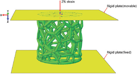
Boundary conditions of the trabecular porous scaffold in finite element analysis.
2.6. Statistical analysis
Statistical analysis was conducted using SPSS 25.0 (IBM Corporation, Armonk, NY). Acquired data were represented as the mean ± standard deviation. Statistically significant differences were analyzed by one-way analysis of variance ANOVA and Student’s t-test. P < 0.05 was considered statistically significant.
3. Results
3.1. Porous structure characterization
Figure 4A shows the photographs of AM-fabricated trabecular Ta scaffolds with different porosities. The structures of the as-prepared samples were substantially consistent with those of the designed models. The average porosities of as-prepared porous Ta scaffolds, derived from the dry weighing method, were approximately 65%, 75%, and 85%. Figure 4B displays the optical micrographs of trabecular Ta scaffolds, indicating that the struts were connected firmly. The surface of the struts was remarkably dense and smooth without microparticle adherence. No processing defects or cracks were found on the struts. Table 1 compares the porous structure characteristics of as-fabricated specimens with those of the designed models. The average strut diameter of as-fabricated samples was slightly larger than that of the designed models, whereas the porosity and pore size were smaller than those of the designed models. The P values of these differences were all >0.05. Figure 5 shows the SEM micrographs of trabecular Ta scaffolds. AM-fabricated trabecular Ta scaffolds exhibited an interconnected porous structure and can be a potential biomimetic model of cancellous bone. Ta powders fused completely. The pore size and strut diameter of these specimens can be measured from SEM images. The strut diameters along different directions were consistent. EDS was conducted on 3 different positions (P1, P2, and P3). The results in Figure 6 showed that 3 elements, Ta, C, and O, were identified on AM-fabricated Ta scaffolds, and their average contents were 93.6%, 3.5%, and 2.9%, respectively.
Figure 4.
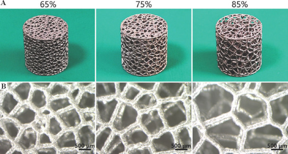
(A) Photographs and (B) optical micrographs of additive manufacturing-fabricated trabecular Ta scaffolds with porosities of 65%, 75%, and 85%.
Table 1.
Comparison of the porous characteristics of AM-fabricated trabecular Ta scaffolds with those of the designed models
| Models | Porosity (%) | Strut diameter (μm) | Average pore size (μm) | |||
|---|---|---|---|---|---|---|
|
|
|
|
||||
| Design | Fabricated | Design | Fabricated | Design | Fabricated | |
| 1 | 67 | 64.8±2.6 | 250 | 261.5±22.3 | 600 | 583.6±21.6 |
| 2 | 77 | 75.3±1.7 | 250 | 259.2±25.5 | 800 | 779.8±34.2 |
| 3 | 87 | 84.6±2.3 | 250 | 256.7±19.4 | 1000 | 986.3±45.4 |
Figure 5.
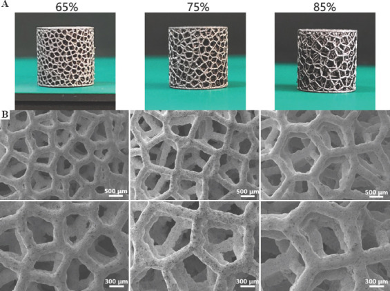
(A) Photographs and (B) scanning electron microscopy images of additive manufacturing AM-fabricated trabecular Ta scaffolds with porosities of 65%, 75%, and 85%.
Figure 6.
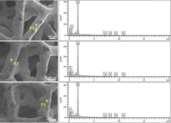
Scanning electron microscopy images and energy-dispersive X-ray spectroscopy patterns showing the chemical compositions of additive manufacturing-fabricated trabecular Ta scaffolds at positions P1, P2, and P3.
3.2. Investigation of compressive behavior
The compressive stress–strain curves of AM-fabricated trabecular Ta scaffolds with porosities of 65%, 75%, and 85% are shown in Figure 7A(a), (b), and (c), respectively. The compressive stress–strain curves of the 6 specimens of each porosity are nearly overlapping, demonstrating excellent reproducible process ability of LPBF technology. The average compressive stress–strain curves of porous Ta scaffolds with these 3 different porosities are shown in Figure 7B. Due to the superior ductility of porous Ta scaffolds, no maximum compressive stress or strain was registered during static compression testing, which is consistent with the results of other studies[5,30]. The compressive stress–strain curves of AM-fabricated trabecular Ta scaffolds exhibit 3 distinct deformation phases: linear elastic, plastic deformation, and densification. To conveniently calculate elastic modulus (E) and yield strength (σy), the average compressive stress–strain curves of trabecular Ta scaffolds with porosities of 65%, 75%, and 85% within 0 – 5 strain are shown in Figure 7C. As shown in Figure 7C, the elastic modulus was calculated as the gradient of the straight line at the beginning of stress–strain curves, and the yield strength, the stress at 0.2% plastic strain, was extracted from stress–strain curves. As shown in Table 2, the elastic moduli of AM-fabricated trabecular Ta scaffolds with porosities of 65%, 75%, and 85% were 3.0 ± 0.2, 2.2 ± 0.3, and 1.1 ± 0.1 GPa, respectively, and their yield strengths were 35.7 ± 0.8 (σy1), 19.5 ± 0.6 (σy2), and 11.9 ± 0.5 (σy3) MPa, respectively. The yield strains of all tested samples lie in the range between 1% and 2%.
Figure 7.
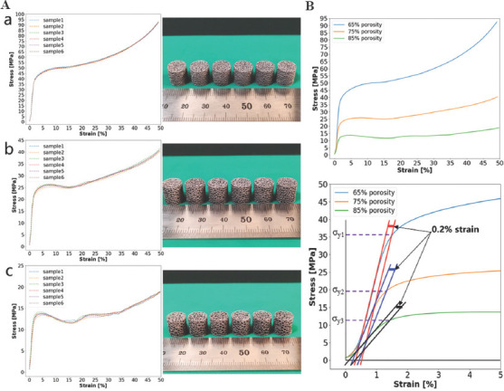
(A) Compressive stress–strain curves and photographs of additive manufacturing (AM)-fabricated trabecular Ta scaffolds with porosities of (a) 65%, (b) 75%, and (c) 85%. The average compressive stress–strain curves of AM-fabricated trabecular Ta scaffolds with porosities of 65%, 75%, and 85%: (B) 0 – 50% strain; (C) 0 – 5% strain.
Table 2.
Compressive mechanical properties of AM-fabricated trabecular Ta scaffolds and human cancellous bone
| Testing specimen | Porosity (%) | Yield strength (MPa) | Elastic modulus (GPa) |
|---|---|---|---|
| Ta scaffolds | 65 | 35.7±0.8 | 3.0±0.2 |
| 75 | 19.5±0.6 | 2.2±0.3 | |
| 85 | 11.9±0.5 | 1.1±0.1 | |
| Human cancellous bone | 50 – 90 | 6.6 – 36.2 | 0.88 – 3.4[2,31-35] |
3.3. Material failure study
Figure 8 illustrates the geometrical morphologies of trabecular Ta scaffolds with porosities of 65%, 75%, and 85% under compressive strains of 0, 20%, and 50%. They demonstrated ductile deformation during compression tests, and no macroscopic cracks were found with a strain up to 50%. Figure 9 shows the stress–strain curve and failed specimen of trabecular Ti6Al4V scaffold obtained from the previous study[36]. An obvious shear fracture band along the inclination of 45° with respect to the loading direction was found on the trabecular Ti6Al4V scaffold. SEM micrographs (Figure 10) suggest that strut deformation and fractures appeared on the outside of the AM-fabricated trabecular Ta scaffolds with porosities of 65%, 75%, and 85% under compressive loads. Most microcracks occurred at conjunctions, and the rest of them appeared on the struts. The fractured struts were twisted greatly. Figure 11 displays the SEM micrographs of the ductile fracture surface of AM-fabricated Ta sample after tensile fracture failure. The interior collapse characterizations of AM-fabricated trabecular Ta scaffolds with porosities of 65%, 75%, and 85% under compressive loading are shown in Figures 12-14, respectively. Optical microscope (OM) photographs indicate that both the strut distribution on the polished cross-section of annealed and unannealed specimens that underwent compression are consistent with the uncompressed specimen (control group), which facilitates the identification of collapse characterizations of trabecular Ta scaffolds. In comparison with the control group, only part of the struts inside porous Ta scaffolds deformed plastically or fractured due to limited compressive strain. Three representative collapse characterizations on the polished cross sections of metallographic specimens for each porosity group were chosen to collect EBSD micrographs. For trabecular Ta scaffolds with porosity of 65% (Figure 12), fractures occurred at positions a and b of unannealed specimens (a3 and b3), whereas no deformation or fracture was found on annealed specimens at the same position (a2 and b2). Identical fractures were observed at positions c of both annealed and unannealed specimens (c2 and c3). For trabecular Ta scaffolds with porosity of 75% (Figure 13), a bigger fracture at position d was observed on the unannealed specimen (d3) than that observed on the annealed specimen (d2). Both fractures occurred at the joints of struts despite their different fracture sites. Similarly, a bigger fracture at position e was observed on the unannealed specimen (e3) than that observed on the annealed specimen (e2). An obvious fracture at the joints of struts was found at position f of the unannealed specimen (f3), whereas no deformation or fracture was found on the annealed specimen at the same position (f2). For trabecular Ta scaffolds with porosity of 85% (Figure 14), fractures occurred at the positions k, m, and n of either annealed or unannealed specimens (k3, m2, m3, n2, and n3), except for the position k of the annealed specimen (k2).
Figure 8.
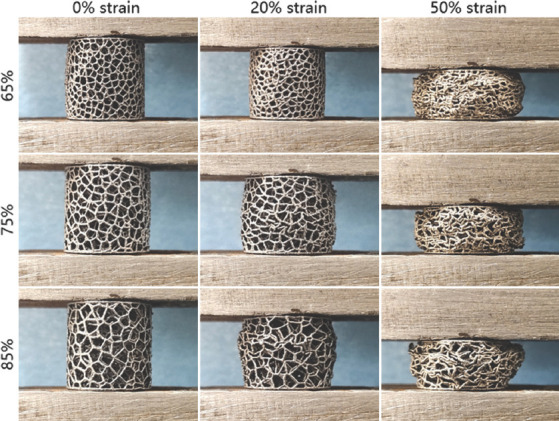
Geometric morphologies of trabecular Ta scaffolds with porosities of 65%, 75%, and 85% under strains of 0, 20%, and 50%, respectively.
Figure 9.
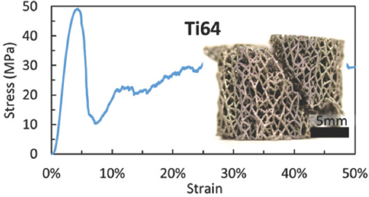
Stress–strain curve and the failed specimen of the trabecular Ti6Al4V scaffold (from ref.[36] licensed under Creative Commons Attribution license).
Figure 10.
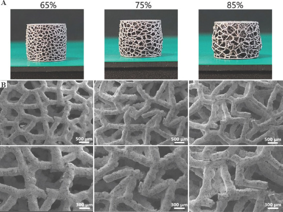
(A) Macroscopic photographs and (B) scanning electron microscopy micrographs of additive manufacturing-fabricated trabecular Ta scaffolds with porosities of 65%, 75%, and 85% after compression.
Figure 11.

Scanning electron microscopy micrographs of the ductile fracture surface of additive manufacturing-fabricated Ta sample after tensile fracture failure.
Figure 12.
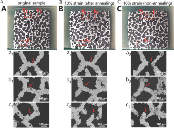
Optical microscope photographs and electron backscattered diffraction micrographs of the metallographic specimens of trabecular Ta scaffolds with porosity of 65%: (A) Uncompressed original sample. (B) Annealed compressive. (C) unannealed compressive samples.
Figure 14.
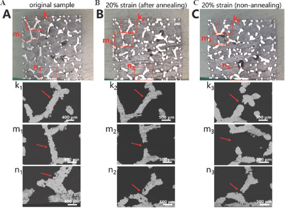
Optical microscope photographs and electron backscattered diffraction micrographs of the metallographic specimens of trabecular Ta scaffolds with porosity of 85%: (A) Uncompressed original. (B) Annealed compressive. (C) Unannealed compressive sample.
Figure 13.
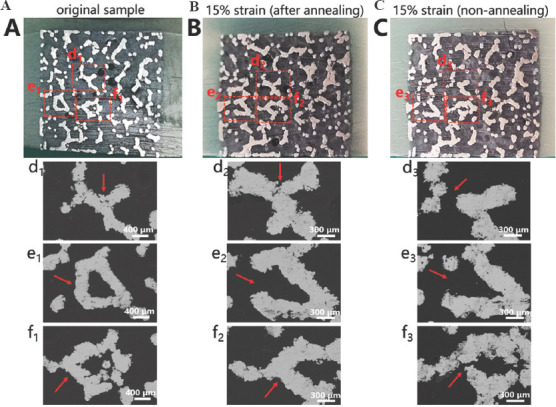
Optical microscope photographs and electron backscattered diffraction micrographs of the metallographic specimens of trabecular Ta scaffolds with porosity of 75%; (A) Uncompressed original. (B) Annealed compressive. (C) Unannealed compressive samples.
3.4. FEA
Figure 15 displays the FEA results of trabecular Ta scaffolds with porosities of 65%, 75%, and 85% within the range of linear elastic deformation. The red color indicates stress concentration in the scaffolds, indicating that more deformation or fracture has occurred in these areas. From the stress distribution diagram, the stress of trabecular Ta scaffolds under uniaxial compressive loading mainly concentrates at the junctions of struts, which is consistent with the results of compressive experiments. Stress distribution inside the trabecular Ta scaffold is illustrated in the longitudinal section view of the FEA model. Under uniaxial compressive loading, trabecular Ta scaffolds can gradually transmit load through their interconnecting struts to the overall structure, rather than bearing the load in a local area. The longitudinal (parallel to the direction of compressive load) struts bear more stress than the transverse struts. Under the same compressive strain, the stress on the struts of trabecular Ta scaffolds gradually decreases as the porosity increases. The stress on the struts of trabecular Ta scaffolds with porosity of 65% is the largest among the scaffolds with the 3 porosities.
Figure 15.
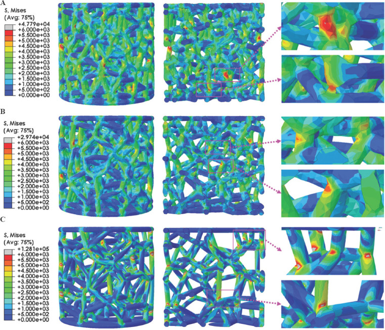
3D and longitudinal section views of finite element analysis results of trabecular Ta scaffolds with porosities of (A) 65%, (B) 75%, and (C) 85%.
4. Discussion
LPBF-based AM technology is suitable for the fabrication of porous metallic scaffolds due to its high precision and processing repeatability[7,37,38]. In this study, LPBF was employed to manufacture porous Ta scaffolds consisting of trabecular structures with various porosities (65%, 75%, and 85%) and an identical strut diameter (250 μm). Morphological analysis revealed that as-fabricated specimens exhibited fully interconnecting and stochastically distributed porous structures (Figures 4 and 5) resembling cancellous bone. The struts had notably dense and smooth appearance after sandblasting, indicating that the starting Ta powders were fully fused during LPBF-based AM. The microstructural examination (Figure 5) revealed dense struts in the AM-fabricated trabecular Ta scaffolds after sandblasting. No obvious processing defects or fractures were found on the struts. However, an uneven secondary morphology with slight irregularities was observed on the surfaces of Ta struts. Although these imperfections are unfavorable to the mechanical properties of trabecular Ta scaffolds, they may be beneficial to improvement of osteoblast adhesion, migration, and proliferation. The measurement results of the gravimetric method indicate that the porosities of AM-fabricated trabecular Ta scaffolds were approximately 2% smaller than those of the designed models (Table 1), which can be explained by the over-sintering phenomenon presented at the edge of the machining path. Over-sintering creates a thicker strut than that of the designed model, resulting in a smaller porosity and pore size compared with those of the designed models. Porosity and pore size are significant parameters for porous implants. In this study, the porosities and pore sizes of AM-fabricated trabecular Ta scaffolds were in the range 65 – 85% and 580 – 980 μm, respectively. The porosity of human cancellous bone lies in the range 50 – 90%[31,34]. If the porosity of the implant is too small, the ingrowth of new bone and blood vessels will be hindered, which is not conducive to the functional reconstruction of the defective bone tissue and the structural stability of the implant. However, excessive porosity will reduce the mechanical strength of the implant[30]. Studies have shown that porous Ta scaffolds with porosity in the range 60–85% are not only conducive to cell adhesion, migration, proliferation, differentiation, and mineralization but also promote new bone ingrowth and vascularization[4,5,7,9]. The pore size of <1000 μm facilitates oxygen exchange and nutrient transportation and enhances the osteoconductivity and osseointegration of porous implants[39-41]. Moreover, pore diameters of >300 μm have been shown to promote implant vascularization[42,43]. Therefore, AM-fabricated trabecular Ta scaffolds in this work have suitable porous structure characteristics for orthopedic implants.
Sufficient yield strength and relatively low elastic modulus, matched with those of the host bone, are favorable for enhancing the long-term stability of the implants, especially in the load-bearing area. An excessive elastic modulus leads to a disproportionate stress distribution on the implant–bone interface, ultimately resulting in peri-prosthetic osteolysis and implant failure[44]. As listed in Table 2, the yield strength and elastic modulus of trabecular Ta scaffolds that underwent annealing were in the range 11.9 – 35.7 MPa and 1.1 – 3.0 GPa, respectively, and negatively correlated with porosity. The yield strength and elastic modulus of human cancellous bone are in the range 6.6 – 36.2 MPa and 0.88 – 3.4 GPa, respectively[2,31-33,35]. The mechanical properties of AM-fabricated trabecular Ta scaffolds matched well with those of the human cancellous bone. Compared with the compressive stress–strain curves of LPBF-fabricated porous Ti6Al4V scaffolds published previously[35,45], the stress–strain curves of trabecular Ta scaffolds (Figure 7) exhibited a longer plastic deformation, indicating the high ductility of AM-fabricated porous Ta scaffolds. The compressive stress–strain curves in this study are similar to those in other porous Ta-related studies[5,27,30]. Therefore, AM-fabricated trabecular Ta scaffolds exhibit ideal mechanical properties making them a promising bone reconstruction candidate in tissue engineering.
Investigating mechanical reliability of implants under compressive loads is an essential mechanical behavior evaluation prior to animal studies and clinical trials. The previous studies have reported different deformation behaviors and failure mechanisms of porous scaffolds, which not only depend on the geometrical morphology, size, porous architecture, and fabrication technique, but also are affected by material property. Li et al.[46] fabricated diamond-lattice AlSi10Mg scaffolds using LPBF, which exhibited a macroscopic fracture band along the inclination of 45° with respect to the loading direction during compression testing. Cracks initially occurred in the lower struts. Petit et al.[47] reported that CoCrMo cubic lattice structures fabricated by electron beam melting (EBM) presented a progressive buckling of the vertical struts, leading to final collapse during compression testing. The initiation of the deformation is affected by fabrication defects. Yang et al.[48] investigated the mechanical behaviors of open-cell magnesium alloy foams with cubic and diamond unit cells under compression. The cubic-cell foams were subjected to a buckling–bending–collapse failure mode, which propagated layer by layer until the whole structure failed, whereas the failure mode of diamond-cell foams was mainly plastic failure determined by the bending deformation in the whole structure. Li et al.[49] reported a brittle fracture behavior occurred on the upper struts of EBM-fabricated Ti6Al4V scaffolds with rhombic dodecahedron cells under compression testing. Zhang et al.[50] observed a 45° shear behavior in the LPBF-fabricated CuSn bcc-lattice structures with a porosity of 87% during compression testing. However, when the porosity decreased to 66%, the mechanical behavior of the CuSn porous structure turned into a uniform compression deformation. Similarly, Cosma et al.[51] and Ghouse et al.[36] observed a shear deformation failure at an angle of approximately 45° on the LPBF-fabricated Ti6Al7Nb lattice structures and trabecular Ti6Al4V scaffolds (Figure 9) during compression testing. The macroscopic shear fracture band represents a brittle deformation behavior, indicating that Ti alloys possess poor ductility and mechanical reliability. In this work, the AM-fabricated trabecular Ta scaffolds exhibited plastic failure during compression testing. No obvious macroscopic shear fracture band was observed on the overall structures, demonstrating the excellent ductility and mechanical reliability of the porous Ta scaffolds. Considering that excessive compressive strain greatly affects the strut distribution inside the porous specimens, a relatively small compressive strain was set to study the failure mechanism of trabecular Ta scaffolds to maintain the initial state after fractures occurred. Although part of the struts was twisted and fractured under compressive loading based on the macroscopic photographs of compressed samples (Figure 10A), the overall structure has not changed greatly, indicating that AM-fabricated trabecular Ta scaffolds have good toughness and structural stability. From the SEM images in Figure 10B, we deduce that material failure results from the deformation and fracture of Ta struts. Most microcracks occurred at conjunctions, and the rest appears on the struts. During the compression tests, the transverse struts (perpendicular to the loading direction) mainly bear tensile stress. Therefore, it is significantly important to study the tensile deformation behavior of AM-fabricated Ta parts. Figure 11 displays the SEM micrographs of the ductile fracture surface of AM-fabricated Ta specimens after tensile fracture failure. Numerous typical ductile dimples were clearly observed on the fracture surface, exhibiting the plastic fracture characteristics of AM-fabricated Ta specimens. In this study, VPIR was used for the 1st time to study the collapse behaviors inside the porous Ta scaffolds. The EBSD micrographs of trabecular Ta scaffolds with various porosities (Figures 12-14) show that most fractures occurred at the conjunctions of struts, which is consistent with the SEM images of external collapse characterization (Figure 10B). From the comparison results of Figure 12 (a2) and (a3), Figure 12 (b2) and (b3), Figure 13 (f2) and (f3), and Figure 14 (k2) and (k3), the fracture characteristics of unannealed samples were more obvious than those of the annealed samples, indicating that annealing can significantly improve the fracture resistance and structural stability of porous Ta. However, fractures also occurred at positions c (Figure 12(c2)), e (Figure 13(e2)), m (Figure 14(m2)), and n (Figure 14(n2)) of annealed samples, which is comparable to those of the unannealed samples. It can be explained by the fact that the struts at these positions bear more load under uniaxial compressive loading than the surrounding struts.
To further theoretically investigate the collapse mechanism of trabecular Ta scaffolds under compressive loading, FEA simulations were conducted to predict and understand the stress distribution and deformation behavior on the same model as the experimental specimens. The compressive strain during FEA simulation was set within the range of elastic deformation, comparable to the FEA of porous structures in other studies[52-55]. The results (Figure 15) revealed that the stress on the struts of trabecular Ta scaffolds gradually decreases with the increase in porosity under the same compressive strain since the length of the struts of trabecular Ta scaffolds is positively correlated with porosity. Stress on the struts gradually decreases from the conjunction to the middle[46]. The stress on the struts of the trabecular Ta scaffold with porosity of 65% is the largest as a result of the shortest struts. Correspondingly, the trabecular Ta scaffold with porosity of 85% exhibits the minimum stress distribution on the struts owing to the longest struts. The stress of trabecular Ta scaffolds primarily concentrates on the conjunctions of struts and vertical struts, where fractures occurred during uniaxial static compression testing. Similar FEA results can be found in other studies[56-59]. Consequently, FEA-generated compressive stress distribution and material deformation are in good agreement with those found experimentally. However, it should be noted that the stiffness and strength obtained by FEA simulation are higher than those obtained in the compression tests. Some of the reasons for this fact could be the surface roughness or irregularities in the strut area randomly produced during laser fusion process. The process imperfections on the struts can reduce the mechanical properties of porous Ta scaffolds and result in the stress concentrations which provides opportunities for the collapse of the structures under compressive loads. In addition, the sharp angles at the conjunctions of struts easily result in stress concentration during compression testing. An effective solution for this problem is to introduce the optimized radius at the nodes. Li et al.[46] studied the influence of different optimized radius at the nodes on the mechanical behavior and failure modes of the diamond lattice structure. They concluded that the introduction of an optimized radius releases the stress concentration at the nodes and improves the mechanical reliability of porous structures. Moreover, the stress distribution gradually shifts from the node to the middle of the struts as the optimized radius increases. Therefore, based on the results of FEA, model optimization of trabecular Ta scaffolds can be performed to strengthen the vertical struts and make the connection of struts smoother, resulting in a more uniform stress distribution over the whole structure.
5. Conclusions
Trabecular Ta scaffolds with porosities of 65%, 75%, and 85% were designed and fabricated by LPBF-based AM, and their porous architectures and microstructures were characterized. The compressive mechanical behavior and failure mechanism of the scaffolds were investigated by compression testing and FEA. The main conclusions are summarized as follows:
1) The fabricated Ta scaffolds exhibited favorable pore structure characteristics for bone tissue ingrowth, which match well with those of the designed models. Porosity has a significant effect on compressive mechanical properties. As the porosity decreased from 85% to 65%, the compressive yield strength and elastic modulus increased from 11.9 MPa to 35.7 MPa and from 1.1 GPa to 3.0 GPa, respectively, which lie in the range of those of the cancellous bone.
2) AM-fabricated trabecular Ta scaffolds showed excellent ductility and mechanical reliability. They exhibited plastic failure resulting from the deformation and fracture of Ta struts during compression testing. No macroscopic cracks were found when the scaffolds were subjected to strain up to 50%. Most microcracks occurred at conjunctions, and the remaining ones appeared on the struts.
3) FEA simulations revealed that the stress on the struts of trabecular Ta scaffolds gradually decreased with the increase in porosity under the same compressive strain. The stress concentration primarily appeared on the conjunctions of struts and vertical struts under compressive loading. The FEA results are in good agreement with the experimental compressive results. Model optimization can be performed by introducing an optimized radius at the nodes to release the stress concentration and strengthen the deformation resistance of trabecular Ta scaffolds.
Acknowledgments
The authors are grateful to the National Key Research and Development Program of China (grant No. 2020YFC1107500) for financial support. Xia Jin would like to thank the Key Lab of Industrial Fluid Energy Conservation and Pollution Control (Qingdao University of Technology), Ministry of Education, PR China. Xiaopeng Li would like to acknowledge the financial support from Australian Research Council (ARC) Discovery Early Career Researcher Award (DECRA) DE190101495.
Appendix
Publisher’s note
Whioce Publishing remains neutral with regard to jurisdictional claims in published maps and institutional affiliations.
Conflict of interest
The authors declare that they have no known competing financial interests or personal relationships that could have appeared to influence the work reported in this paper.
Author’s contributions
J.Y. wrote the manuscript, conceptualized the idea, and supervised this research. H.G. and D.Z. conducted the experiments. X.J. and X.L. revised the manuscript and supervised this research. F.Z. and H.C. collected and reviewed the detailed research results. S.Z. proposed the porous structure design and created the 3D models.
References
- 1.Matsuno H, Yokoyama A, Watari F, et al. Biocompatibility and Osteogenesis of Refractory Metal Implants, Titanium, Hafnium, Niobium, Tantalum and Rhenium. Biomaterials. 2001;22:1253–62. doi: 10.1016/s0142-9612(00)00275-1. https://doi.org/10.1016/S0142-9612(00)00275-1. [DOI] [PubMed] [Google Scholar]
- 2.Ruperez E, Manero JM, Riccardi K, et al. Development of Tantalum Scaffold for Orthopedic Applications Produced by Space-holder Method. Mater Des. 2015;83:112–19. https://doi.org/10.1016/j.matdes.2015.05.067. [Google Scholar]
- 3.Wang Q, Qiao YQ, Cheng MQ, et al. Tantalum Implanted Entangled Porous Titanium Promotes Surface Osseointegration and Bone Ingrowth. Sci Rep. 2016;6:13. doi: 10.1038/srep26248. https://doi.org/10.1038/srep26248. [DOI] [PMC free article] [PubMed] [Google Scholar]
- 4.Hacking S, Bobyn J, Toh KK, et al. Fibrous Tissue Ingrowth and Attachment to Porous Tantalum. J Biomed Mater Res. 2000;52:631–8. doi: 10.1002/1097-4636(20001215)52:4<631::aid-jbm7>3.0.co;2-6. https://doi.org/10.1002/1097-4636(20001215)52:4<631:AID-JBM7>3.0.CO;2-6. [DOI] [PubMed] [Google Scholar]
- 5.Wauthle R, van der Stok J, Yavari SA, et al. Additively Manufactured Porous Tantalum Implants. Acta Biomater. 2015;14:217–25. doi: 10.1016/j.actbio.2014.12.003. https://doi.org/10.1016/j.actbio.2014.12.003. [DOI] [PubMed] [Google Scholar]
- 6.Bandyopadhyay A, Mitra I, Shivaram A, et al. Direct Comparison of Additively Manufactured Porous Titanium and Tantalum Implants Towards In Vivo Osseointegration. Addit Manuf. 2019;28:259–66. doi: 10.1016/j.addma.2019.04.025. https://doi.org/10.1016/j.addma.2019.04.025. [DOI] [PMC free article] [PubMed] [Google Scholar]
- 7.Wang H, Su KX, Su LZ, et al. Comparison of 3D-printed Porous Tantalum and Titanium Scaffolds on Osteointegration and Osteogenesis. Mater Sci Eng C Mater Biol Appl. 2019;104:9. doi: 10.1016/j.msec.2019.109908. https://doi.org/10.1016/j.msec.2019.109908. [DOI] [PubMed] [Google Scholar]
- 8.Dou XJ, Wei XW, Liu G, et al. Effect of Porous Tantalum on Promoting the Osteogenic Differentiation of Bone Marrow Mesenchymal Stem Cells In Vitro through the MAPK/ERK Signal Pathway. J Orthop Transl. 2019;19:81–93. doi: 10.1016/j.jot.2019.03.006. https://doi.org/10.1016/j.jot.2019.03.006. [DOI] [PMC free article] [PubMed] [Google Scholar]
- 9.Guo Y, Xie K, Jiang WB, et al. In Vitro and In Vivo Study of 3D-Printed Porous Tantalum Scaffolds for Repairing Bone Defects. ACS Biomater Sci Eng. 2019;5:1123–33. doi: 10.1021/acsbiomaterials.8b01094. https://doi.org/10.1021/acsbiomaterials.8b01094. [DOI] [PubMed] [Google Scholar]
- 10.Van Steenkiste T, Gorkiewicz D. Analysis of Tantalum Coatings Produced by the Kinetic Spray Process. J Therm Spray Techn. 2004;13:265–73. https://doi.org/10.1361/10599630419418. [Google Scholar]
- 11.Bobyn JD, Stackpool GJ, Hacking SA, et al. Characteristics of Bone Ingrowth and Interface Mechanics of a New Porous Tantalum Biomaterial. J Bone Joint Surg Br. 1999;81:907. doi: 10.1302/0301-620x.81b5.9283. https://doi.org/10.1302/0301-620X.81B5.9283. [DOI] [PubMed] [Google Scholar]
- 12.Jenkins DR, Odland AN, Sierra RJ, et al. Minimum Five-Year Outcomes with Porous Tantalum Acetabular Cup and Augment Construct in Complex Revision Total Hip Arthroplasty. J Bone Joint Surg Am. 2017;99:7. doi: 10.2106/JBJS.16.00125. https://doi.org/10.2106/JBJS.16.00125. [DOI] [PubMed] [Google Scholar]
- 13.Huang W, Gong X, Sandiford TE, et al. Outcome after a New Porous Tantalum Rod Implantation for Treatment of Early-stage Femoral Head Osteonecrosis. Ann Transl Med. 2019;7:11. doi: 10.21037/atm.2019.08.86. https://doi.org/10.21037/atm.2019.08.86. [DOI] [PMC free article] [PubMed] [Google Scholar]
- 14.Peng K, Wang Y, Zhu J, et al. Repair of Non-traumatic Femoral Head Necrosis by Marrow Core Decompression with Bone Grafting and Porous Tantalum Rod Implantation. Pak J Med Sci. 2020;36:1392. doi: 10.12669/pjms.36.6.2176. https://doi.org/10.12669/pjms.36.6.2176. [DOI] [PMC free article] [PubMed] [Google Scholar]
- 15.Zhou YS, Zhu YC. Three-dimensional Ta Foams Produced by Replication of NaCl Space-holders. Mater Lett. 2013;99:8–10. https://doi.org/10.1016/j.matlet.2013.02.068. [Google Scholar]
- 16.Wang H, Li QJ, Wang Q, et al. Enhanced Repair of Segmental Bone Defects in Rabbit Radius by Porous Tantalum Scaffolds Modified with the RGD Peptide. J Mater Sci-Mater Med. 2017;28:10. doi: 10.1007/s10856-017-5860-4. https://doi.org/10.1007/s10856-017-5860-4. [DOI] [PubMed] [Google Scholar]
- 17.Sukumar VR, Golla BR, Shaik MA, et al. Modeling and Characterization of Porous Tantalum Scaffolds. Trans Indian Inst Met. 2019;72:935–49. https://doi.org/10.1007/s12666-018-01556-1. [Google Scholar]
- 18.Maconachie T, Leary M, Lozanovski B, et al. SLM Lattice Structures:Properties, Performance, Applications and Challenges. Mater Des. 2019;183:108137. https://doi.org/10.1016/j.matdes.2019.108137. [Google Scholar]
- 19.Gong H, Rafi K, Gu H, et al. Analysis of Defect Generation in Ti-6Al-4V Parts Made Using Powder Bed Fusion Additive Manufacturing Processes. Addit Manuf. 2014;1:87–98. https://doi.org/10.1016/j.addma.2014.08.002. [Google Scholar]
- 20.Sing SL, Kuo CN, Shih CT, et al. Perspectives of Using Machine Learning in Laser Powder Bed Fusion for Metal Additive Manufacturing. Virtual Phys Prototy. 2021;16:372–86. https://doi.org/10.1080/17452759.2021.1944229. [Google Scholar]
- 21.Qin YC, Qi QF, Shi PZ, et al. Automatic Determination of Part Build Orientation for Laser Powder Bed Fusion. Virtual Phys Prototype. 2021;16:29–49. https://doi.org/10.1080/17452759.2020.1832793. [Google Scholar]
- 22.Sing SL, Huang S, Goh GD, et al. Emerging Metallic Systems for Additive Manufacturing:In-Situ Alloying and Multi-metal Processing in Laser Powder Bed Fusion. Prog Mater Sci. 2021;119:100795. https://doi.org/10.1016/j.pmatsci.2021.100795. [Google Scholar]
- 23.Liu R, Chen Y, Liu Y, et al. Topological Design of a Trabecular Bone Structure With Morphology and Mechanics Control for Additive Manufacturing. IEEE Access. 2021;9:11123–33. https://doi.org/10.1109/ACCESS.2021.3050745. [Google Scholar]
- 24.Wang GJ, Shen LD, Zhao JF, et al. Design and Compressive Behavior of Controllable Irregular Porous Scaffolds:Based on Voronoi-Tessellation and for Additive Manufacturing. ACS Biomater Sci Eng. 2018;4:719–27. doi: 10.1021/acsbiomaterials.7b00916. https://doi.org/10.1021/acsbiomaterials.7b00916. [DOI] [PubMed] [Google Scholar]
- 25.Yang JZ, Jin X, Gao HR, et al. Additive Manufacturing of Trabecular Tantalum Scaffolds by Laser Powder Bed Fusion:Mechanical Property Evaluation and Porous Structure Characterization. Mater Charact. 2020;170:110694. https://doi.org/10.1016/j.matchar.2020.110694. [Google Scholar]
- 26.Huang S, Narayan RL, Tan JH, et al. Resolving the Porosity-unmelted Inclusion Dilemma during In-Situ Alloying of Ti34Nb Via Laser Powder Bed Fusion. Acta Mater. 2021;204:116522. https://doi.org/10.1016/j.actamat.2020.116522. [Google Scholar]
- 27.Nadammal N, Mishurova T, Fritsch T, et al. Critical Role of Scan Strategies on the Development of Microstructure, Texture, and Residual Stresses during Laser Powder Bed Fusion Additive Manufacturing. Addit Manuf. 2021;38:101792. https://doi.org/10.1016/j.addma.2020.101792. [Google Scholar]
- 28.Chen HS, Li QJ, Liu G. The Development Status and Trend of Environmental Friendly Vacuum Pressure Impregnation Resin at Home and Abroad. Insul Mater. 2011;2 https://doi.org/10.16790/j.cnki.1009-9239.im.2011.02.010. [Google Scholar]
- 29.Škoro G, Bennett J, Edgecock T, et al. Dynamic Young's Moduli of Tungsten and Tantalum at High Temperature and Stress. J Nucl Mater. 2011;409:40–6. https://doi.org/10.1016/j.jnucmat.2010.12.222. [Google Scholar]
- 30.Shimko DA, Shimko VF, Sander EA, et al. Effect of Porosity on the Fluid Flow Characteristics and Mechanical Properties of Tantalum Scaffolds. J Biomed Mater Res B. 2005;73:315–24. doi: 10.1002/jbm.b.30229. https://doi.org/10.1002/jbm.b.30229. [DOI] [PubMed] [Google Scholar]
- 31.Martens M, Van Audekercke R, Delport P, et al. The Mechanical Characteristics of Cancellous Bone at the Upper Femoral Region. J Biomech. 1983;16:971–83. doi: 10.1016/0021-9290(83)90098-2. https://doi.org/10.1016/0021-9290(83)90098-2. [DOI] [PubMed] [Google Scholar]
- 32.Turner CH, Cowin SC, Rho JY, et al. The Fabric Dependence of the Orthotropic Elastic Constants of Cancellous Bone. J Biomech. 1990;23:549–61. doi: 10.1016/0021-9290(90)90048-8. https://doi.org/10.1016/0021-9290(90)90048-8. [DOI] [PubMed] [Google Scholar]
- 33.Keaveny TM, Morgan EF, Niebur GL, et al. Biomechanics of Trabecular Bone. Annu Rev Biomed Eng. 2001;3:307–33. doi: 10.1146/annurev.bioeng.3.1.307. [DOI] [PubMed] [Google Scholar]
- 34.Renders G, Mulder L, Van Ruijven L, et al. Porosity of Human Mandibular Condylar Bone. J Anat. 2007;210:239–48. doi: 10.1111/j.1469-7580.2007.00693.x. https://doi.org/10.1111/j.1469-7580.2007.00693.x. [DOI] [PMC free article] [PubMed] [Google Scholar]
- 35.Yang E, Leary M, Lozanovski B, et al. Effect of Geometry on the Mechanical Properties of Ti-6Al-4V Gyroid Structures Fabricated Via SLM:A Numerical Study. Mater Des. 2019;184:108165. https://doi.org/10.1016/j.matdes.2019.108165. [Google Scholar]
- 36.Ghouse S, Babu S, Nai K, et al. The Influence of Laser Parameters, Scanning Strategies and Material on the Fatigue Strength of a Stochastic Porous Structure. Addit Manuf. 2018;22:290–301. https://doi.org/10.1016/j.addma.2018.05.024. [Google Scholar]
- 37.Sing SL, Wiria FE, Yeong WY. Selective Laser Melting of Lattice Structures:A Statistical Approach to Manufacturability and Mechanical Behavior. Robot Cim Int Manuf. 2018;49:170–180. https://doi.org/10.1016/j.rcim.2017.06.006. [Google Scholar]
- 38.Huang S, Sing SL, de Looze G, et al. Laser Powder Bed Fusion of Titanium-tantalum Alloys:Compositions and Designs for Biomedical Applications. J Mech Behav Biomed Mater. 2020;108:103775. doi: 10.1016/j.jmbbm.2020.103775. https://doi.org/10.1016/j.jmbbm.2020.103775. [DOI] [PubMed] [Google Scholar]
- 39.Petite H, Viateau V, Bensaid W, et al. Tissue-engineered Bone Regeneration. Nat Biotechnol. 2000;18:959–63. doi: 10.1038/79449. https://doi.org/10.1038/79449. [DOI] [PubMed] [Google Scholar]
- 40.Hollister SJ. Porous Scaffold Design for Tissue Engineering. Nat Mater. 2005;4:518–24. doi: 10.1038/nmat1421. https://doi.org/10.1038/nmat1683. [DOI] [PubMed] [Google Scholar]
- 41.Chen Z, Yan X, Yin S, et al. Influence of the Pore Size and Porosity of Selective Laser Melted Ti6Al4V ELI Porous Scaffold on Cell Proliferation, Osteogenesis and Bone Ingrowth. Mat Sci Eng C Mater. 2020;106:110289. doi: 10.1016/j.msec.2019.110289. https://doi.org/10.1016/j.msec.2019.110289. [DOI] [PubMed] [Google Scholar]
- 42.Eichi T, Hiroko T, Hideaki I, et al. Pore Size of Porous Hydroxyapatite as the Cell-substratum Controls BMP-induced Osteogenesis. J Biochem. 1997;121:317–24. doi: 10.1093/oxfordjournals.jbchem.a021589. https://doi.org/10.1093/oxfordjournals.jbchem.a021589. [DOI] [PubMed] [Google Scholar]
- 43.Karageorgiou V, Kaplan D. Porosity of 3D Biomaterial Scaffolds and Osteogenesis. Biomaterials. 2005;26:5474–91. doi: 10.1016/j.biomaterials.2005.02.002. https://doi.org/10.1016/j.biomaterials.2005.02.002. [DOI] [PubMed] [Google Scholar]
- 44.Niinomi M, Nakai M. Titanium-based Biomaterials for Preventing Stress Shielding Between Implant Devices and Bone. Int J Biomater. 2011;2011:836587. doi: 10.1155/2011/836587. https://doi.org/10.1155/2011/836587. [DOI] [PMC free article] [PubMed] [Google Scholar]
- 45.Ahmadi S, Campoli G, Yavari SA, et al. Mechanical Behavior of Regular Open-cell Porous Biomaterials Made of Diamond Lattice Unit Cells. J Mech Behav Biomed Mater. 2014;34:106–15. doi: 10.1016/j.jmbbm.2014.02.003. https://doi.org/10.1016/j.jmbbm.2014.02.003. [DOI] [PubMed] [Google Scholar]
- 46.Li ZH, Nie YF, Liu B, et al. Mechanical Properties of AlSi10Mg Lattice Structures Fabricated by Selective Laser Melting. Mater Des. 2020;192:108709. https://doi.org/10.1016/j.matdes.2020.10∅. [Google Scholar]
- 47.Petit C, Maire E, Meille S, et al. CoCrMo Cellular Structures Made by Electron Beam Melting Studied by Local Tomography and Finite Element Modelling. Mater Charact. 2016;116:48–54. https://doi.org/10.1016/j.matchar.2016.04.006. [Google Scholar]
- 48.Yang A, Wen C, Hodgson PD, et al. Investigation of Cell Shape Effect on the Mechanical Behaviour of Open-cell Metal Foams. Comp Mater Sci. 2012;55:1–9. https://doi.org/10.1016/j.commatsci.2011.11.030. [Google Scholar]
- 49.Li S, Xu Q, Wang Z, et al. Influence of Cell Shape on Mechanical Properties of Ti-6Al-4V Meshes Fabricated by Electron Beam Melting Method. Acta Biomater. 2014;10:4537–47. doi: 10.1016/j.actbio.2014.06.010. https://doi.org/10.1016/j.actbio.2014.06.010. [DOI] [PubMed] [Google Scholar]
- 50.Zhang MK, Yang YQ, Wang D, et al. Microstructure and Mechanical Properties of CuSn/18Ni300 Bimetallic Porous Structures Manufactured by Selective Laser Melting. Mater Des. 2019;165:107583. https://doi.org/10.1016/j.matdes.2019.107583. [Google Scholar]
- 51.Cosma C, Drstvensek I, Berce P, et al. Physical-Mechanical Characteristics and Microstructure of Ti6Al7Nb Lattice Structures Manufactured by Selective Laser Melting. Materials. 2020;13:4123. doi: 10.3390/ma13184123. https://doi.org/10.3390/ma13184123. [DOI] [PMC free article] [PubMed] [Google Scholar]
- 52.Shin J, Kim S, Jeong D, et al. Finite Element Analysis of Schwarz P Surface Pore Geometries for Tissue-engineered Scaffolds. Math Probl Eng. 2012;2012:865–83. https://doi.org/10.1155/2012/694194. [Google Scholar]
- 53.Soro N, Brassart L, Chen Y, et al. Finite Element Analysis of Porous Commercially Pure Titanium for Biomedical Implant Application. Mat Sci Eng A Struct. 2018;725:43–50. https://doi.org/10.1016/j.msea.2018.04.009. [Google Scholar]
- 54.Zhang B, Pei X, Zhou C, et al. The Biomimetic Design and 3D Printing of Customized Mechanical Properties Porous Ti6Al4V Scaffold for Load-bearing Bone Reconstruction. Mater Des. 2018;152:30–9. https://doi.org/10.1016/j.matdes.2018.04.065. [Google Scholar]
- 55.Du Y, Liang H, Xie D, et al. Finite Element Analysis of Mechanical Behavior, Permeability of Irregular Porous Scaffolds and Lattice-based Porous Scaffolds. Mater Res Express. 2019;6:105407. https://doi.org/10.1088/2053-1591/ab3ac1. [Google Scholar]
- 56.Patel R, Lu M, Diermann SH, et al. Deformation Behavior of Porous PHBV Scaffold in Compression:A Finite Element Analysis Study. J Mech Behav Biomed Mater. 2019;96:1–8. doi: 10.1016/j.jmbbm.2019.04.030. https://doi.org/10.1016/j.jmbbm.2019.04.030. [DOI] [PubMed] [Google Scholar]
- 57.Peng WM, Liu YF, Jiang XF, et al. Bionic Mechanical Design and 3D Printing of Novel Porous Ti6Al4V Implants for Biomedical Applications. J Zhejiang Univ Sci B. 2019;20:647–59. doi: 10.1631/jzus.B1800622. https://doi.org/10.1631/jzus.B1800622. [DOI] [PMC free article] [PubMed] [Google Scholar]
- 58.Yang L, Yan C, Cao W, et al. Compression-Compression Fatigue Behaviour of Gyroid-type Triply Periodic Minimal Surface Porous Structures Fabricated by Selective Laser Melting. Acta Mater. 2019;181:49–66. https://doi.org/10.1016/j.actamat.2019.09.042. [Google Scholar]
- 59.Zhao L, Pei X, Jiang L, et al. Bionic Design and 3D Printing of Porous Titanium Alloy Scaffolds for Bone Tissue Repair. Compos Part B Eng. 2019;162:154–61. https://doi.org/10.1016/j.compositesb.2018.10.094. [Google Scholar]


