

Abstract
The morphologies and structures of the scaffold have a significant influence on their mechanical and biological properties. In this work, different types of porous structures: Triply periodic minimal surface-Schwarz primitive (P), body-centered cubic, and cubic pore-shaped (CPS) hydroxyapatite scaffolds with ~70% porosity were fabricated through digital light processing (DLP) 3D printing technology. The compressive properties and in vitro cell evaluations such as cell proliferation and attachment morphology of these scaffolds were systematically compared. The results showed that the CPS scaffolds exhibited the highest compressive strength (~22.5 MPa) and modulus (~400 MPa). In addition, the CPS scaffolds also performed the most active cell metabolisms as compared to other two structures, which may account for the larger pore size and smaller curvature of the substrate. This study provides a general guidance for the fabrication and selection of porous bone scaffolds processed by DLP 3D printing.
Keywords: Nano-hydroxyapatite, Digital light processing, Bone scaffolds, 3D printing
1. Introduction
Bone defects caused by trauma injuries, diseases, and complications that occurred in the bone regenerating process have been a critical medical problem in the current society[1-4]. However, bone defects cannot heal themselves without surgical interventions when the defects are larger than the critical size[5-7]. Traditional surgical operations, including autografts and allografts, have inevitable drawbacks, such as supply shortage, the need for second surgery, and occurrence of immune responses, which increase the implantation risk and hinder their further applications in clinic[8-10].
With rapid development in recent years, bone tissue engineering (BTE) is considered a new substitutive therapy for treating bone lesions. Scaffolds play an important role in BTE for providing a three-dimensional (3D) environment for cell attachment, adhesion, growth, and proliferation until the injured bone has regenerated its own properties and functions. There are several requirements for tissue engineered scaffolds. The paramount requirements for BTE scaffolds are biocompatibility and non-toxicity[10-12]. Hydroxyapatite (HA) is chemically similar to the inorganic phase of native bone, possessing incomparable biological advantages such as osteoconductivity, osteoinductivity, and biocompatibility. Therefore, it is widely regarded as a promising material for bone scaffolds. Second, bone scaffolds should have sufficient mechanical strength and stiffness to provide physical support for cell activities. Besides, the scaffolds should also have porous structures with adequate interconnected pores to facilitate the diffusion of nutrients and oxygen as well as cell ingrowth[10,12]. Notably, the characteristics of scaffold structures (pore shape, pore size, porosity, etc.) not only affect the stress distribution but also have a close relation with cell behaviors. Therefore, improving the properties of tissue engineered scaffolds by designing different structures has been an attractive research hotspot. Especially, with the advancement of computational design and advanced manufacturing, the design and fabrication of scaffolds with complex structures have gained many attentions in BTE field.
Triply periodic minimal surface (TPMS) is nowadays a popular structure that has been widely investigated for BTE scaffold due to the advantages of zero mean curvature and large surface area. Blanquer et al. fabricated eight TPMS scaffolds using the biocompatible material, poly(trimethylene carbonate), by service-level agreement to investigate the biofunctional role of surface curvature of scaffolds[13]. Their results showed that different TPMS structures exhibited distinct permeabilities and thus influenced the tissue formation. However, there were no further illustrations about the in vitro evaluations caused by the difference of the permeabilities of the scaffolds. Besides, the structure stability of TPMS scaffolds was investigated by Lu et al.[14]. They manufactured the TPMS-based scaffolds with Ca-silicate bioceramics and compared the structural and mechanical stability between TPMS-based and structure-based scaffolds. It revealed that TPMS-based (skeletal- I-graph and wrapped package-graph, sheet gyroid) scaffolds had higher appreciable specific flexural strength than structure-based scaffolds but lack of further discussions on in vitro evaluations. The similar conclusion that the TPMS-P HA scaffolds performed high flexural strength up to 92.4 MPa was also reported in Yao et al.’s work[15]. Furthermore, they also pointed out the TPMS-P had good cell proliferation through the in vitro evolution[15]. Body-centered cubic (BCC) structure, discovered in crystals structures, was also used for tissue engineering applications. Huo et al. fabricated BCC Ti-6Al-4V (TC4) scaffolds by selective laser melting and investigated the compression deformation behavior of BCC structure[16]. The result showed that the BCC structure could benefit the formation of the smaller and regular α’ martensite, which could improve the compressive strength of TC4 scaffolds. Meanwhile, Caravaggi et al. revealed that the BBC structure had higher ultimate tensile strength than that of the circular pore-shaped scaffolds, and good cell viability and proliferation rate[17]. Obviously, different advanced scaffold designs, such as TPMS and BCC, have emerged in BTE in recent years. However, systematic comparisons among new structures and traditional structures, such as cubic pore-shaped (CPS) scaffolds, in both mechanical properties and in vitro cell evaluations, are scarce, and thus, deeper investigations are needed.
To identify the difference and properties of various scaffolds, the fabrication approaches should be carefully considered. Traditional approaches, such as salt leaching, freeze drying, and gas foaming, are commonly applied in HA scaffold fabrication, whereas these techniques have inevitable limitations, such as uncontrolled pore size and poor pore interconnectivity[18]. Recently, additive manufacturing, such as binder jetting (3DP), selective laser sintering (SLS), and direct ink writing (DIW), has emerged as an efficient way to fabricate HA scaffolds with complex structures. As for 3DP and SLS, the general challenges include the relatively low resolution and powder entrapment in small pore of printed scaffolds. Sag and collapse in the DIW process are still a big obstacle for scaffold fabrication[3]. Digital light processing (DLP), possessing the advantages of high accuracy and resolution, is a powerful way to fabricate scaffolds with specific pore shape and interconnected pores. Before printing bioceramic 3D objects through DLP, the photosensitive slurry, containing ceramic powders, resin matrix, etc., should be prepared in advance. The successful printing by DLP largely depends on the good performance of the bioceramic slurry. As for slurry preparation, ceramic dispersion is a big challenge, particularly for nano-sized ceramic which can facilitate the mechanical properties of the ceramic parts. The nano-sized particles are difficult to be homogeneously dispersed in the slurry because they are prone to agglomeration due to the higher surface energy. The dispersity of nano-sized ceramic slurry is influenced by the dispersant and concentration, which was investigated by Sun et al.[19] His work revealed that the nano-sized zirconia slurry was well dispersed by adding 3 wt. % Disperbyk (BYK). A proper dispersant and corresponding concentration are significant to stable dispersity of slurry, which was also evidenced by Ding et al.’s work[20]. Besides, the slurry containing nano-sized ceramic particles exhibits difficulties in printing accuracy since there are more scattering centers that enhance the overcure in an unexpected area[21]. Ju et al.’s study showed that the printability of nano-sized zirconia slurry could be optimized by mixing in the specific ratio of micron-sized powders due to the decrease of scattering center’s number and sustained solid-like behaviors[22].
In this work, nano-sized HA ceramic slurry was prepared and processed using DLP 3D printing. The rheological properties, curing abilities, debinding, and sintering strategy were systematically investigated. Afterward, the TPMS-P, BCC, and CPS scaffolds with a same porosity were designed and fabricated under optimized parameters. The compressive properties and in vitro biological evaluation in cell proliferation and attachment morphologies of three structures were compared and studied. Our research is expected to offer an insight into guide the bioceramic scaffold fabrication and the selection for BTE applications.
2. Materials and methods
2.1. Materials
The HA powders (diameter: 20 nm; length: 270 nm) were supplied by Nanjing Emperor Nano Materials Co., Ltd (Jiangsu, China); 1, 6-hexanediol diacrylate (HDDA, Shanghai Yinchang Materials Co., China) was selected as the monomer of the slurry. Its two reactive functionalities ensure a sufficient cross-linking in curing[23]. The dispersant-BYK for powder surface modification was provided by BYK Additive and Instrument, Germany. TPO (Diphenyl (2, 4, 6-trimethylbenzoyl)) phosphine oxide from Shanghai Macklin Biochemical Co. was used as photoinitiator. 3-[4, 5-dimethylthiazol-2-yl]-2, 5-diphenyltetrazolium bromide (MTT) was provided by Invitrogen (Thermal Fisher Scientific, USA). Dulbecco’s Modified Eagle’s Medium (DMEM), fetal bovine serum, and penicillin-streptomycin were provided by Gibco (Thermal Fisher Scientific, USA). Paraformaldehyde (PFA) was supplied by Alfa Aesar.
2.2. Slurry preparation
Before slurry preparation, surface modification of the nano-HA powders is necessary for homogeneous and stable dispersion[24,25]. The modification process is schematically shown in Figure 1. Raw HA powders were dried at 100°C for 12 h and mixed with the dispersant BYK in ethanol. The solution was stirred for 2 h at room temperature and dried in an oven at 50°C for 24 h. The modified HA powders were mixed with photoinitiator resin (HDDA, TPO) in a specific proportion. A number of zirconia beads were added into the slurry. After vigorously mixing in a Turbula shaker-mixer (Turbula T2F, Basel, Switzerland) for above 6 h, the nano-HA slurry was obtained.
Figure 1.
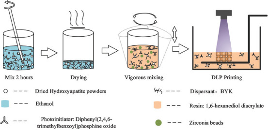
Slurry preparation and digital light processing printing.
2.3. Design and fabrication of scaffolds
The TPMS-P surface belongs to a member of the TPMS family, which can be defined by the specific mathematical equation[26,27], referring to Equation (2.1) where is defined as unit size and represents the expansion of surface. In this work, the P structure of scaffolds was designed by MATLAB.

BCC and CPS structures with symmetric features were designed by CAD software. All scaffolds were designed with the same porosity value, that is, ~65%.
The scaffolds were printed by a top-down DLP 3D printer (405 nm light source) with a 30 um layer thickness (~10 mJ/cm2 energy dose, 1.5 s exposure time). First, the as-prepared nano-HA slurry was poured into the tank until the volume of slurry can meet the need of printing models. The 3D models were sliced into 2D images by a slicing software. Basing on the slicing data, the slurry was selectively cured by ultraviolet light layer by layer till the printing was fully accomplished. After finishing the printing process, the green parts were immersed in a mixture consisting of monomers and ethanol, and washed by an ultrasonic cleaning to remove the residual slurry.
To determine the debinding and sintering strategy, the thermal decomposition of the green part was analyzed using thermogravimetric analysis (TGA) (Discovery, TA Instruments, USA) with a heating speed of 10°C/min from 40°C to 700°C. According to the TGA result, debinding and sintering strategy were conducted to obtain the final HA bioceramic scaffolds.
2.4. Characterization
The rheological property was investigated using the rotational rheometer (Anton Parr MCR 92, Anton Paar GmbH, Austria) equipped with a 50 mm diameter parallel plate with the shear rate from 1 S−1 to 100 S−1. Under light exposure with various energy doses, the cure depth of a single layer was measured by the digital micrometer (MDC-25PX, Mitutoyo, Japan) to evaluate the cure capability of slurry. The phase constitution of the scaffolds was confirmed by the X-ray diffractometer (SmartLab, Rigaku, Japan) in range from 10° to 70° in scanning speed of 10°/min. The morphology and grains of sintered scaffolds were observed by scanning electron microscopy (SEM, Merlin, ZEISS, Germany). The samples were coated with a layer of platinum (Pt) to improve the electrical conductivity. The thickness and pore size of sintered scaffolds were measured by microscope (Axio Observer 3, ZEISS) and its supporting software. The linear shrinkage was calculated by a digital caliper based on the dimensional difference of the parts before and after sintering. The linear shrinkage was compensated in the design process for accurately obtaining the expected size of scaffolds.
The porosity of the 3D models of the scaffolds was measured by the CAD software. Their real porosity was calculated by the Equations 2.2 to 2.4.


Where, Vtotal, Vscaffold, mscaffold, ρ0, a, b, and h are total volume of bulk scaffold size, volume of the scaffold, mass of scaffolds, reference density (3.18 g/cm3), length, width, and height, respectively.
Compressive test was evaluated by a universal testing machine (TST, China) with a loading speed of 0.5 mm/min. The overall sizes of the scaffolds used for compressive testing were5.5 × 5.5 × 5.5 mm (three units in each direction).
2.5. Cell culture
In this study, rat bone mesenchymal stem cells (rBMSCs) isolated from a rat’s bone marrow were used to evaluate the cell morphology and proliferation of HA scaffolds. The cells were seeded onto the HA scaffolds at a density of 2 × 10³ cells per well in a 48-well cell culture plate and cultured in DMEM medium at 37°C in a CO2 incubator for 1, 4, and 7 days. At predetermined times, 300 μl MTT was added to each well and the plate was incubated at 37°C for 4 h. Then, the medium was removed and (dimethyl sulfoxide, Aladdin) was added into each well for 10 min. The absorbance of each well was directly measured at 540 nm by a microplate reader. Besides, the cells were fixed by 4% PFA (Alfa) and then dehydrated in a series of graded ethanol. Afterward, the cell attachment morphologies were observed by SEM. The sizes of samples for in vitro evaluations were set as 5.5 × 5.5 × 1.8 mm.
2.6. Statistical analysis
The data of compressive testing, structure parameters, and MTT assay data are expressed as means ± standard deviation. Besides, the results of compressive testing and MTT assay were analyzed by one-way analysis of variance and Tukey’s post hoc test, in which the significance values, P-values, were set to <0.05.
3. Results and discussion
3.1. Slurry properties and fabrication of the HA ceramics
The geometry accuracy and density of the green parts are influenced by the rheological behavior of the slurry during the printing process. Figure 2A shows the rheological behavior of nano-HA slurry. Obviously, the slurry exhibited a shear thinning behavior, which could be described by Equation 3.1[25,28,29].
Figure 2.
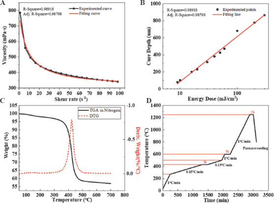
Slurry properties, thermogravimetric analysis of HA green part, and heating strategy. (A) Viscosity with different shear rates. (B) The relationship between cure depth and energy doses. (C) TGA and derivative thermogravimetry (DTG) curve. (D) Debinding and sintering strategy.
Where, η0 and η∞ refer to the asymptotic viscosity at zero and infinite shear rate, α is a constant relating to the dimension of time, γ represents apparent shear rate, and n is a value to evaluate the shear thinning behavior. After fitting the data with Equation 3.1, as shown in Figure 2A, the fitting result showed n = 1.0087 ± 0.05036 (> 8) and signified an apparent shear thinning behavior of the HA slurry[25]. Besides, the viscosity of the slurry was approximately 380 mPa·s at 52 S−1, indicating that the slurry had a low viscosity which can be used for the following printing. The low viscosity of the slurry is a guarantee of self-leveling in the recoating. Moreover, it can reduce the risks of producing bubbles in the slurry to improve the printing precision.
To optimize the printing parameter, the effect of exposing energy on the cure depth was examined. Figure 2B shows the result of cure depth with various exposing energy doses. The relationship between cure depth and energy doses can be described by Beer-Lambert law, Equation (3.2)[30]:

Where, Sd and Ec represent the cure sensitivity of slurry and critical exposure energy dose, respectively. Based on the measured data, the fitting function is as follows:

From Equation 3.3, the value of cure sensitivity reached 299.8, indicating high curing abilities and fast photo-polymerization speed.
During the DLP printing, the cure depth should exceed the printing layer thickness to guarantee a sufficient interface combination between layers to avoid the delamination and laminar crack in the sintering[31]. Therefore, considering both the cure depth of the slurry and printer set-up, 30 mm was set as the printing layer thickness. ~10 mJ/cm2 of energy dose with cure depth of ~105 mm was correspondingly applied in the printing.
An optimized debinding strategy was beneficial for obtaining crack-free HA scaffold. The thermal decomposition of the green parts and the corresponding debinding strategy is shown in Figure 2C and D. Before ~300°C, there was rarely mass loss in the green parts[32]. Most of the mass loss occurred in the temperature range between ~360°C and ~480°C. The peak value of the fastest mass loss occurred at ~430°C. Exceeding ~500°C, the mass of green parts was stable at ~55 wt. %.
According to the TGA result, the debinding strategy was determined, as shown in Figure 2D. In the temperature range between ~270°C and ~500°C, the heating rate was set as 0.15°C/min. Three hours were held at the highest speed of the decomposition to provide sufficient time for removing the organic phase of green parts. Besides, the other heating stages were heated with 1°C/min up to 1250°C. After holding 3 h, the temperature in the furnace was gradually decreased to 800°C in 100 min to remove the residual thermal stress of sintered scaffolds.
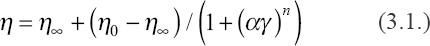
X-ray diffraction was performed to confirm the phase composition of the HA powder and sintered HA ceramic. The standard peaks of HA powders (~25.9°, ~31.9°, ~33.0°, etc.) have an agreement with the HA PDF card (PDF#73-1731) showing that the purity of the HA powders, as shown in Figure 3. After sintering, the new peaks, such as ~31.1° and ~34.5°, were detected demonstrating the phase transformation from HA to beta-tricalcium phosphate (b-TCP) occurred. However, the strong peaks of HA verified that HA was still abundant in the sintered ceramics. The transformation was common, which was also published in many studies[33,34]. The presence of b-TCP is beneficial for BTE applications as it may increase the dissolution abilities.
Figure 3.
X-ray diffraction pattern of hydroxyapatite powder and the sintered hydroxyapatite ceramics.
3.2. Dimensional observation of scaffolds
The overall morphologies of the three types of scaffolds are shown in Figure 4A. The upper and lower rows of scaffolds were the green parts and final sintered HA ceramics, respectively. The dimensional difference revealed the linear shrinkage of the scaffolds during the thermal treatment. Form the green part to the sintered part, the linear shrinkage was ~30% in X, Y, and Z directions. The geometric information of 3D models, the green bodies, and the sintered scaffolds are presented in Table 1.
Figure 4.
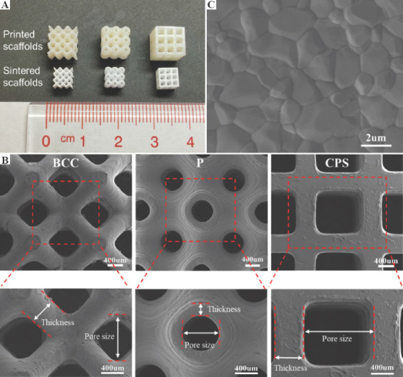
Image of the scaffolds. (A) The printed (upper row) and sintered (lower row) scaffolds. (B) Scanning electron microscopy (SEM) image of surface grains in sintered scaffolds. (C) SEM of the body-centered cubic, primitive, and cubic pore-shaped scaffolds in the top view and their magnified views.
Table 1.
Geometric information of the designed and sintered scaffolds
| Structure of scaffolds | Thickness/µm | Pore size/µm | Porosity/% | Size/mm | |||||||||
|---|---|---|---|---|---|---|---|---|---|---|---|---|---|
|
|
|
|
|
||||||||||
| CAD | cCAD | Printed | Sintered | CAD | cCAD | Printed | Sintered | CAD | Sintered | X | Y | Z | |
| BCC | 540 | 760 | 717.57±14.65 | 470.89±9.61 | 850 | 1280 | 1304.84±17.68 | 903.90±15.90 | 65.20 | 70.43±1.25 | 5.40±0.04 | 5.39±0.03 | 5.40±0.05 |
| P | 280 | 420 | 361.04±13.88 | 211.38±6.48 | 630 | 910 | 940.08±13.76 | 673.40±20.63 | 64.20 | 67.29±0.72 | 5.43±0.02 | 5.43±0.02 | 5.43±0.03 |
| CPS | 550 | 800 | 755.43±13.04 | 520.73±6.63 | 1100 | 1590 | 1617.69±17.02 | 1182.39±14.69 | 64.94 | 68.93±1.01 | 5.39±0.03 | 5.41±0.03 | 5.41±0.04 |
Figure 4B demonstrates the morphologies of three types of scaffolds captured in the top view. The unique features of each scaffold were clearly displayed and the pores were fully interconnective without any blockages or deformations. In the magnified image, the thickness and pore size of the green parts and sintered scaffolds were measured by Observer microscope, which are presented in Table 1. For these three structures of printed green parts, compared with the compensated design, the thickness was smaller and the pore size was bigger because of the polymerization shrinkage[35,36]. In the views of the sintered HA scaffolds with three structures, the sintered thickness was in a range from ~210 μm to ~520 μm, whereas the pore size was in a range from ~670 μm to ~1180 μm. The sintered thickness of scaffolds was smaller but the sintered pore size was larger than the design, which is accounted for the interior shrinkage of scaffolds after sintering. As previously report, a pore size of >300 μm is recommended for better vascularization, high oxygenation, and better osteogenesis of implants[37]. Bružauskaitė et al. summarized the impact of pore size on cell functioning[38]. Their work indicated that the pore size in a range from 100 to 800 μm benefited the cell migration grow inside and outside of 3D scaffolds. As for scaffolds with larger pore sizes from 500 μm to 1500 μm, Huri et al. and Velioglu et al. revealed that large pore size has positive effects on cell proliferation, alkaline phosphatase (ALP) activity, and calcium deposition[39,40]. In this work, the pore sizes of P, BCC, and CPS scaffolds were within the suggested range. Figure 4C shows the grains of HA scaffolds after sintering at 1250°C. The clear equiaxed grains and noticeable grain boundaries could be observed in SEM image, showing a good crystalline quality of the sintered parts.
The sintered porosity of three kinds of scaffolds was calculated by Equations 2.2 – 2.4, as shown in Table 1. ~65% of porosity was set as the given design parameter in P, BCC, and CPS structures of scaffolds. After sintering, the porosity of scaffolds (~70%) was larger than that of the designed ones. The interior shrinkage caused by the thermal sintering would be the main reason for larger porosity.
3.3. Mechanical property
Scaffolds should provide sufficient physical support for cell activities, and compressive strength of the scaffolds is an important index to evaluate the mechanical stability of scaffolds[34]. The compressive strengths of scaffolds with BCC, P, and CPS structures are shown in Figure 5A. The result revealed that the CPS scaffold had the highest compressive strength among the scaffolds, up to ~22.5 MPa on average. This value was significantly higher than that of P and BBC scaffolds (~5.9 MPa and ~3.4 MPa, respectively). It indicated that CPS structure had improved compressive properties of scaffold for ceramic material at the same porosity. For CPS scaffolds, the external forces are along the vertical direction to the ground and almost parallel to internal supporting struts, indicating that the vertical parts of the interior structures were completely compressed under the external forces. Particularly, ceramics materials have the characteristic of brittleness and tend to be strong in face of compression instead of bending or tension[41]. However, in terms of BCC and P structures, the internal supporting struts are not parallel to the external forces, which make the bending occur inside the scaffolds and further lead to fracture in advance. The compressive strength of the scaffolds in this study showed great competitiveness as compared to the published works, which was mainly attributed to the nano-sized HA. For example, Yao et al. used HA with a particles size of 3.97 mm and fabricated P structure scaffolds with ~74% porosity, whose mechanical strength was ~4.09 MPa[15]. Feng et al. fabricated the CPS scaffolds with ~50% porosity using HA with a particle size of ~8 mm; the scaffold has a compressive strength of ~2 MPa[33].
Figure 5.
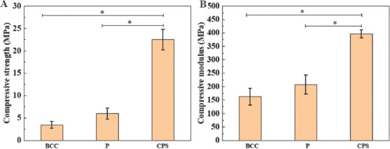
Mechanical properties of body-centered cubic, primitive, and cubic pore-shaped scaffolds. (A) Compressive strength. (B) Compressive modulus. * represents P < 0.05.
Modulus of the scaffolds is another key element that should be analyzed. The mismatching of the modulus between native bone and implants could result in stress shielding, thus leading to the original bone loss[42]. Figure 5B shows the compressive modulus of these three types of scaffolds. The CPS scaffold still performed the highest modulus, ~400 MPa, and significantly higher than the P and BCC scaffolds. The compressive strength and modulus of cancellous bone range from 1.6 MPa to 4.6 MPa and from 22.9 MPa to 431 MPa, respectively[43-45]. All scaffolds with different structures designed in this study exhibited mechanical properties that are comparable with the native cancellous bone, indicating their potential in bone applications.
3.4. Biological testing in vitro
MTT assay was conducted to evaluate the cell proliferation of rBMSCs cultured onto the P, BCC, and CPS scaffolds for 1, 4, and 7 days. The increasing absorbance of three scaffolds can be seen with the days of cultivation in Figure 6, indicating that HA scaffolds formed through the mentioned fabrication process were non-cytotoxic and biocompatible. After 7 days cultivation, the cell viability was generally more than ~75% compared with the control group. Meanwhile, the absorbance of both BCC and CPS scaffolds was significantly higher than that of P scaffolds, which revealed that BCC and CPS scaffolds were beneficial for cell metabolisms.
Figure 6.
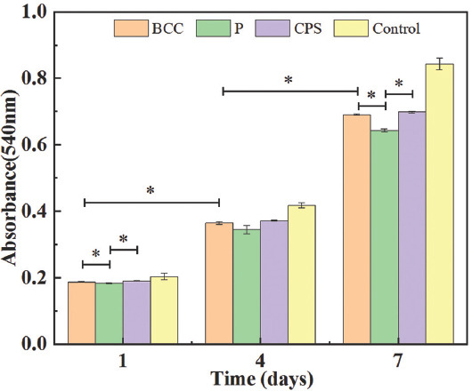
3-[4, 5-Dimethylthiazol-2-yl]-2, 5-diphenyltetrazolium bromide assay for proliferation of rat bone mesenchymal stem cells culturing for 1, 4, and 7 days on three scaffolds. * represents P < 0.05.
Figure 7B-D shows the SEM images of rBMSCs’ morphologies after being cultured for 1, 4, and 7 days on the three types of scaffolds. On day 1, the rBMSCs generally adhered well and maintained the spindle-like morphology, confirming the non-cytotoxicity of the scaffolds[46-51]. In magnified images (Figure 7A), the filopodia adhering on the surface of scaffolds could be seen clearly, indicating a good cell attachment. Cell spreading is a sign of adherence to a substrate, which directly or indirectly regulates the cell metabolism[52-55]. On three types of scaffolds, compared with day 1, the majority of rBMSCs obviously exhibited the spreading behavior on day 4. This suggests that cell metabolism on day 4 was more active than that on day 1, which was in good agreement with the MTT result on day 4, as shown in Figure 6. On day 7, the cell spread of rBMSCs became larger and they formed a thin membrane to cover the scaffolds. The similar processes of the cell membrane covering the scaffolds have been reported[56,57]. This indicates the active attachment of rBMSCs to the scaffolds. Meanwhile, SEM images of day 7 showed that the rBMSCs deposited the extracellular matrix (ECM) on all scaffolds. Particularly, the amount of ECM formed on the surface of CPS scaffolds was obviously higher than that of others. ECM plays a critical role in providing support for cell growth and migration[38]. It may exhibit the metabolism of rBMSCs which are more active on CPS scaffolds, which can explain the highest absorbance at day 7 in Figure 6.
Figure 7.
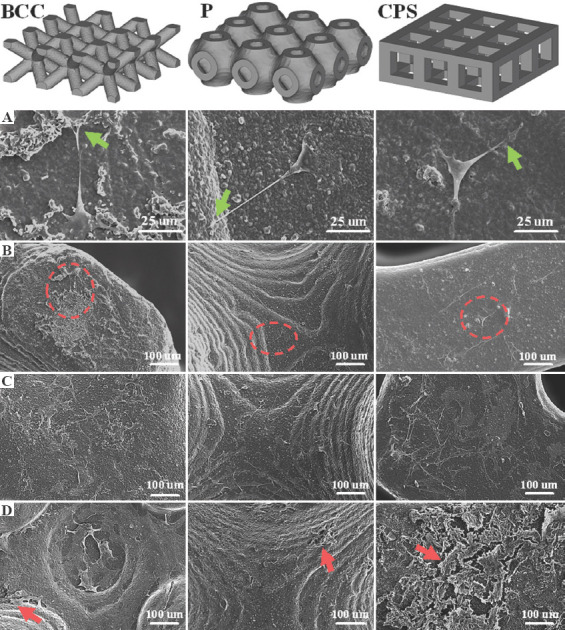
Scanning electron microscopy images of the rat bone mesenchymal stem cells (rBMSCs) morphology and proliferation on body-centered cubic, primitive, and cubic pore-shaped scaffolds. (A) Magnified images of the morphologies of the seeded rBMSCs on the areas which were marked with red circles. rBMSCs proliferation of three scaffolds on (B) day 1, (C) day 4, and (D) day 7. Filopodia are marked with green arrows. Extracellular matrix is marked with red arrows.
According to a report[58], TPMS structures have larger specific surface area, which could provide more room for cell attachment and thus perform better cell proliferation. However, it did not occur in this work as expected. Larger specific surface areas of P scaffolds were not observed in the in vitro biological test (in the CAD models, the surface areas of the P, CPS, and BCC were approximately 157, 151, and 127 mm3, respectively, and the area of P slightly exceeded that of CPS by about 6 mm3). The MTT result showed that surface area may not have a significant effect on short-time cell proliferation when the difference of surface area is not large in different structures of scaffold.
Pore size may be the main reason that leads to the current cell proliferation result since it greatly affects nutrients transport, oxygen diffusion, and waste removal[38,59]. Velioglu et al. reported that the scaffolds with 1.25 mm pore size presented higher cell proliferation than that with 1.0 mm and 0.5 mm on poly(lactic acid) scaffolds[40]. In Huri et al.’s work, the ALP and Ca+ deposition on 1000–1500 mm of scaffolds was obviously more than that on 500–1000 mm and <500 mm of scaffolds[39]. Especially, Huri et al. hypothesized that bigger pore size might lead to the closer cell-biomaterials interactions which would stimulate an osteogenic outcome[39]. In this work, the CPS and BCC scaffolds had a relatively larger pore size (~1180 mm and ~900 mm, respectively). This may improve the supply of nutrients, oxygen diffusion, and waste removal so that the cell metabolism was more active in CPS and BCC scaffolds.
The surface topography is another key factor that affects cell behaviors which further influences cell proliferation. Lee et al. reported that human mesenchymal stem cell had well-spread morphologies with randomly multiple lamellipodia on the flat glass plates[60]. They further pointed out more cell attachment and spreading occur on the substrates with smaller curvatures. Similar conclusions have also been reported[61-63]. As compared with the P and BCC structure, the CPS scaffolds had more flat plates that might result in tight attachment of more cells onto the substrates.
Overall, the difference of cell metabolisms shown in these three types of structures could be attributed to different scaffold geometries, which mainly focus on pore size and surface topology. In detail, higher cell metabolism and more cell proliferation of CPS scaffolds could be observed as compared to that of P and BCC scaffolds, mainly due to the larger pore size and flat surfaces.
4. Conclusions
In this work, nano-sized HA ceramic slurry was prepared and processed using DLP 3D printing. Afterward, the P, BCC, and CPS scaffolds with a same porosity were designed and fabricated under optimized parameters. The compressive properties and in vitro biological evaluations, such as cell proliferation and attachment morphologies of three scaffolds, were compared and studied. The main conclusions are summarized as follows:
The prepared nano-HA slurry exhibited an apparent shear thinning behavior and high curing abilities. The obtained slurry and optimized fabrication process were able to accurately fabricate BCC, P, and CPS scaffolds with high porosity. Besides, the features of each sintered scaffold were maintained and the pores were interconnective without blockages and deformations.
The real porosity of three scaffolds was maintained at a high level, ~ 70%, and the CPS scaffolds exhibited the highest compressive strength and modulus among the three types of scaffolds, up to ~22.5 MPa and ~400 MPa, respectively. All scaffolds showed compressive properties that are comparable with the same properties of native cancellous bone; therefore, the scaffolds hold great potential for bone applications.
All structure scaffolds in this study showed good biocompatibilities and attachment morphologies. The CPS scaffolds presented higher cell metabolisms as compared to BCC and P scaffolds, mainly accounting for the larger pore size and smaller curvature of the substrates.
This study displayed the mechanical properties and in vitro biological responses of the three types of structures at the same porosity. It is expected to offer a view on structure optimization of bone scaffolds to improve cell metabolism and bone regeneration efficiency.
Acknowledgments
This study was supported by the Shenzhen Science and Technology Innovation Commission [Grant No. KQTD20190929172505711], Shenzhen Science and Technology International Cooperation program [Grant No. GJHZ20200731095606021], Shenzhen Science and Technology Program [Grant No. KQTD2017032815444316], and the Guangdong Province International Collaboration Program [Grant No. 2019A050510003]. The authors acknowledge the assistance of SUSTech Core Research Facilities.
Appendix
Publisher’s note
Whioce Publishing remains neutral with regard to jurisdictional claims in published maps and institutional affiliations.
Conflict of interest
The authors declare that they have no conflicts of interest.
Author contributions
H.L. performed the preparation and fabrication of the scaffolds, and mechanical tests. Y.W. conceived and designed the study, and carried out data analysis. S.C. and Y.L. performed biological experiments. H.L. and Y.W. wrote and revised the paper with the help from J.B. and Z.L.
References
- 1.Pilia M, Guda T, Appleford M. Development of Composite Scaffolds for Load-Bearing Segmental Bone Defects. Biomed Res Int. 2013;2013:458253. doi: 10.1155/2013/458253. https://doi.org/10.1155/2013/458253. [DOI] [PMC free article] [PubMed] [Google Scholar]
- 2.Wang X, Ao Q, Tian X, et al. 3D Bioprinting Technologies for Hard Tissue and Organ Engineering. Materials. 2016;9:802. doi: 10.3390/ma9100802. https://doi.org/10.3390/ma9100802. [DOI] [PMC free article] [PubMed] [Google Scholar]
- 3.Lin K, Sheikh R, Romanazzo S, et al. 3D Printing of bioceramic Scaffolds-Barriers to the Clinical Translation:From Promise to Reality, and Future Perspectives. Materials. 2019;12:2660. doi: 10.3390/ma12172660. https://doi.org/10.3390/ma12172660. [DOI] [PMC free article] [PubMed] [Google Scholar]
- 4.Goodman SB, Maruyama M. Inflammation, Bone Healing and Osteonecrosis:From Bedside to Bench. J Inflamm Res. 2020;13:913. doi: 10.2147/JIR.S281941. https://doi.org/10.2147/jir.s281941. [DOI] [PMC free article] [PubMed] [Google Scholar]
- 5.Keating JF, Simpson A, Robinson C. The Management of Fractures with Bone Loss. J Bone Joint Surg Br. 2005;87:142–50. doi: 10.1302/0301-620x.87b2.15874. https://doi.org/10.1302/0301-620X.87B2.15874. [DOI] [PubMed] [Google Scholar]
- 6.Sanders DW, Bhandari M, Guyatt G, et al. Critical-Sized Defect in the Tibia:Is It Critical?Results from the SPRINT Trial. J Orthop Trauma. 2014;28:632–5. doi: 10.1097/BOT.0000000000000194. https://doi.org/10.1097/BOT.0000000000000194. [DOI] [PubMed] [Google Scholar]
- 7.McDermott AM, Herberg S, Mason DE, et al. Recapitulating Bone Development Through Engineered Mesenchymal Condensations and Mechanical Cues for Tissue Regeneration. Sci Transl Med. 2019;11:eaav7756. doi: 10.1126/scitranslmed.aav7756. https://doi.org/10.1126/scitranslmed.aav7756. [DOI] [PMC free article] [PubMed] [Google Scholar]
- 8.Zhu Y, Zhang K, Zhao R, et al. Bone Regeneration with Micro/Nano Hybrid-Structured Biphasic Calcium Phosphate Bioceramics at Segmental Bone Defect and the Induced Immunoregulation of MSCs. Biomaterials. 2017;147:133–44. doi: 10.1016/j.biomaterials.2017.09.018. https://doi.org/10.1016/j.biomaterials.2017.09.018. [DOI] [PubMed] [Google Scholar]
- 9.Klar RM. The Induction of Bone Formation:The Translation Enigma. Front Bioeng Biotechnol. 2018;6:74. doi: 10.3389/fbioe.2018.00074. https://doi.org/10.3389/fbioe.2018.00074. [DOI] [PMC free article] [PubMed] [Google Scholar]
- 10.Roddy E, DeBaun MR, Daoud-Gray A, et al. Treatment of Critical-Sized Bone Defects:Clinical and Tissue Engineering Perspectives. Eur J Orthop Surg Traumatol. 2018;28:351–62. doi: 10.1007/s00590-017-2063-0. https://doi.org/10.1007/s00590-017-2063-0. [DOI] [PubMed] [Google Scholar]
- 11.Khairallah M, Almeshaly H. Present Strategies for Critical Bone Defects Regeneration. Oral Health Case Rep. 2016;2:3. https://doi.org/10.4172/2471-∖.1000127. [Google Scholar]
- 12.Roseti L, Parisi V, Petretta M, et al. Scaffolds for Bone Tissue Engineering:State of the Art and New Perspectives. Mater Sci Eng C. 2017;78:1246–62. doi: 10.1016/j.msec.2017.05.017. https://doi.org/10.1016/j.msec.2017.05.017. [DOI] [PubMed] [Google Scholar]
- 13.Blanquer SB, Werner M, Hannula M, et al. Surface Curvature in Triply-Periodic Minimal Surface Architectures as a Distinct Design Parameter in Preparing Advanced Tissue Engineering Scaffolds. Biofabrication. 2017;9:025001. doi: 10.1088/1758-5090/aa6553. https://doi.org/10.1088/1758-5090/aa6553. [DOI] [PubMed] [Google Scholar]
- 14.Lu F, Wu R, Shen M, et al. Rational Design of Bioceramic Scaffolds with Tuning Pore Geometry by Stereolithography:Microstructure Evaluation and Mechanical Evolution. J Eur Ceram Soc. 2021;41:1672–82. https://doi.org/10.1016/j.jeurceramsoc.2020.10.002. [Google Scholar]
- 15.Yao Y, Qin W, Xing B, et al. High Performance Hydroxyapatite Ceramics and a Triply Periodic Minimum Surface Structure Fabricated by Digital Light Processing 3D Printing. J Adv Ceram. 2021;10:39–48. https://doi.org/10.1007/s40145-020-0415-4. [Google Scholar]
- 16.Huo P, Zhao Z, Bai P, et al. Deformation Evolution and Fracture Mechanism of Porous TC4 Alloy Scaffolds Fabricated Using Selective Laser Melting under Uniaxial Compression. J Alloys Compd. 2021;861:158529. https://doi.org/10.1016/j.jallcom.2020.158529. [Google Scholar]
- 17.Caravaggi P, Liverani E, Leardini A, et al. CoCr Porous Scaffolds Manufactured Via Selective Laser Melting in Orthopedics:Topographical, Mechanical, and Biological Characterization. J Biomed Mater Res B Appl Biomater. 2019;107:2343–53. doi: 10.1002/jbm.b.34328. https://doi.org/10.1002/jbm.b.34328. [DOI] [PubMed] [Google Scholar]
- 18.Bigham A, Foroughi F, Ghomi ER, et al. The Journey of Multifunctional Bone Scaffolds Fabricated from Traditional Toward Modern Techniques. Biodes Manuf. 2020;3:1–26. https://doi.org/10.1007/s42242-020-00094-4. [Google Scholar]
- 19.Sun J, Binner J, Bai J. Effect of Surface Treatment on the Dispersion of Nano Zirconia Particles in Non-Aqueous Suspensions for Stereolithography. J Eur Ceram Soc. 2019;39:1660–7. https://doi.org/10.1016/j.jeurceramsoc.2018.10.024. [Google Scholar]
- 20.Ding G, He R, Zhang K, et al. Dispersion and Stability of SiC Ceramic Slurry for Stereolithography. Ceram Int. 2020;46:4720–9. https://doi.org/10.1016/j.ceramint.2019.10.203. [Google Scholar]
- 21.King BW Jr. Effect of Particle Size and Index of Refraction on Reflectance. J Am Ceram Soc. 1940;23:221–5. https://doi.org/10.1111/j.1151-2916.1940.tb14258.x. [Google Scholar]
- 22.Ju Y, Ha J, Song Y, et al. Optimizing the Printability and Dispersibility of Functionalized Zirconium Oxide/Acrylate Composites with Various Nano-to Micro-Particle Ratios. Ceram Int. 2020;46:26903–10. https://doi.org/10.1016/j.ceramint.2020.07.168. [Google Scholar]
- 23.De Camargo IL, Morais MM, Fortulan CA, et al. A Review on the Rheological Behavior and Formulations of Ceramic Suspensions for Vat Photopolymerization. Ceram Int. 2021;47:11906–21. https://doi.org/10.1016/j.ceramint.2021.01.031. [Google Scholar]
- 24.Sun J, Binner J, Bai J. 3D Printing of Zirconia Via Digital Light Processing:Optimization of Slurry and Debinding Process. J Eur Ceram Soc. 2020;40:5837–44. https://doi.org/10.1016/j.jeurceramsoc.2020.05.079. [Google Scholar]
- 25.Zheng T, Wang W, Sun J, et al. Development and Evaluation of Al2O3-ZrO2 Composite Processed by Digital Light 3D Printing. Ceram Int. 2020;46:8682–8. https://doi.org/10.1016/j.ceramint.2019.12.102. [Google Scholar]
- 26.Yu S, Sun J, Bai J. Investigation of Functionally Graded TPMS Structures Fabricated by Additive Manufacturing. Mater Des. 2019;182:108021. https://doi.org/10.1016/j.matdes.2019.108021. [Google Scholar]
- 27.Vijayavenkataraman S, Zhang L, Zhang S, et al. Triply Periodic Minimal Surfaces Sheet Scaffolds for Tissue Engineering Applications:An Optimization Approach Toward Biomimetic Scaffold Design. ACS Appl Bio Mater. 2018;1:259–69. doi: 10.1021/acsabm.8b00052. https://doi.org/10.1021/acsabm.8b00052. [DOI] [PubMed] [Google Scholar]
- 28.Cross MM. Rheology of non-Newtonian Fluids:A New Flow Equation for Pseudoplastic Systems. J Coll Sci. 1965;20:417–37. https://doi.org/10.1016/0095-8522(65)90022-X. [Google Scholar]
- 29.Barnes HA, Hutton JF, Walters K. An Introduction to Rheology. Amsterdam, Netherlands: Elsevier; 1989. [Google Scholar]
- 30.Griffith ML, Halloran JW. Freeform Fabrication of Ceramics Via Stereolithography. J Am Ceram Soc. 1996;79:2601–8. https://doi.org/10.1111/j.1151-2916.1996.tb09022.x. [Google Scholar]
- 31.Conti L, Bienenstein D, Borlaf M, et al. Effects of the Layer Height and Exposure Energy on the Lateral Resolution of Zirconia Parts Printed by Lithography-Based Additive Manufacturing. Materials. 2020;13:1317. doi: 10.3390/ma13061317. https://doi.org/10.3390/ma13061317. [DOI] [PMC free article] [PubMed] [Google Scholar]
- 32.Wang K, Qiu M, Jiao C, et al. Study on Defect-Free Debinding Green Body of Ceramic Formed by DLP Technology. Ceram Int. 2020;46:2438–46. https://doi.org/10.1016/j.ceramint.2019.09.237. [Google Scholar]
- 33.Feng C, Zhang K, He R, et al. Additive Manufacturing of Hydroxyapatite Bioceramic Scaffolds:Dispersion, Digital Light Processing, Sintering, Mechanical Properties, and Biocompatibility. J Adv Ceram. 2020;9:360–73. https://doi.org/10.1007/s40145-020-0375-8. [Google Scholar]
- 34.Zeng Y, Yan Y, Yan H, et al. 3D Printing of Hydroxyapatite Scaffolds with Good Mechanical and Biocompatible Properties by Digital Light Processing. J Mater Sci. 2018;53:6291–301. https://doi.org/10.1007/s10853-018-1992-2. [Google Scholar]
- 35.Shan J, Yang Z, Chen G, et al. Design and Synthesis of Free-Radical/Cationic Photosensitive Resin Applied for 3D Printer with Liquid Crystal Display (LCD) Irradiation. Polymers. 2020;12:1346. doi: 10.3390/polym12061346. https://doi.org/10.3390/polym12061346. [DOI] [PMC free article] [PubMed] [Google Scholar]
- 36.Guo B, Ji X, Wang W, et al. Highly Flexible, Thermally Stable, and Static Dissipative Nanocomposite with Reduced Functionalized Graphene Oxide Processed Through 3D Printing. Compos B Eng. 2021;208:10, 8598. https://doi.org/10.1016/j.compositesb.2020.10↖. [Google Scholar]
- 37.Karageorgiou V, Kaplan D. Porosity of 3D Biomaterial Scaffolds and Osteogenesis. Biomaterials. 2005;26:5474–91. doi: 10.1016/j.biomaterials.2005.02.002. https://doi.org/10.1016/j.biomaterials.2005.02.002. [DOI] [PubMed] [Google Scholar]
- 38.Bružauskaitė I, Bironaitė D, Bagdonas E, et al. Scaffolds and Cells for Tissue Regeneration:Different Scaffold Pore Sizes-Different Cell Effects. Cytotechnology. 2016;68:355–69. doi: 10.1007/s10616-015-9895-4. https://doi.org/10.1007/s10616-015-9895-4. [DOI] [PMC free article] [PubMed] [Google Scholar]
- 39.Huri PY, Ozilgen BA, Hutton DL, et al. Scaffold Pore Size Modulates In Vitro Osteogenesis of Human Adipose-Derived Stem/Stromal Cells. Biomed Mater. 2014;9:045003. doi: 10.1088/1748-6041/9/4/045003. https://doi.org/10.1088/1748-6041/9/4/045003. [DOI] [PubMed] [Google Scholar]
- 40.Velioglu ZB, Pulat D, Demirbakan B, et al. 3D-Printed Poly (Lactic Acid) Scaffolds for Trabecular Bone Repair and Regeneration:Scaffold and Native Bone Characterization. Connect Tissue Res. 2019;60:274–82. doi: 10.1080/03008207.2018.1499732. https://doi.org/10.1080/03008207.2018.1499732. [DOI] [PubMed] [Google Scholar]
- 41.Edwards K. Selecting Materials for Optimum Use in Engineering Components. Mater Des. 2005;26:469–73. https://doi.org/10.1016/j.matdes.2004.07.004. [Google Scholar]
- 42.van Lenthe GH, de Waal Malefijt MC, Huiskes R. Stress Shielding after Total Knee Replacement May Cause Bone Resorption in the Distal Femur. J Bone Joint Surg Br. 1997;79:117–22. doi: 10.1302/0301-620x.79b1.6808. https://doi.org/10.1302/0301-620X.79B1.0790117. [DOI] [PubMed] [Google Scholar]
- 43.Lindahl O. Mechanical Properties of Dried Defatted Spongy Bone. Acta Orthop Scand. 1976;47:11–9. doi: 10.3109/17453677608998966. https://doi.org/10.3109/17453677608998966. [DOI] [PubMed] [Google Scholar]
- 44.Røhl L, Larsen E, Linde F, et al. Tensile and Compressive Properties of Cancellous Bone. J Biomech. 1991;24:1143–9. doi: 10.1016/0021-9290(91)90006-9. https://doi.org/10.1016/0021-9290(91)90006-9. [DOI] [PubMed] [Google Scholar]
- 45.Giesen E, Ding M, Dalstra M, et al. Mechanical Properties of Cancellous Bone in the Human Mandibular Condyle are Anisotropic. J Biomech. 2001;34:799–803. doi: 10.1016/s0021-9290(01)00030-6. https://doi.org/10.1016/S0021-9290(01)00030-6. [DOI] [PubMed] [Google Scholar]
- 46.Xie J, Zorman J, Indrawati L, et al. Development and Optimization of a Novel Assay to Measure Neutralizing Antibodies Against Clostridium Difficile Toxins. Clin Vaccine Immunol. 2013;20:517–25. doi: 10.1128/CVI.00549-12. https://doi/10.1128/CVI.00549-12. [DOI] [PMC free article] [PubMed] [Google Scholar]
- 47.Lan Y, Jin Q, Xie H, et al. Exosomes Enhance Adhesion and Osteogenic Differentiation of Initial Bone Marrow Stem Cells on Titanium Surfaces. Front Cell Dev Biol. 2020;8:583234. doi: 10.3389/fcell.2020.583234. https://doi.org/10.3389/fcell.2020.583234. [DOI] [PMC free article] [PubMed] [Google Scholar]
- 48.Zheng HZ, Fu XK, Shang JL, et al. Ginsenoside Rg1 Protects Rat Bone Marrow Mesenchymal Stem Cells Against Ischemia Induced Apoptosis Through miR-494-3p and ROCK-1. Eur J Pharmacol. 2018;822:154–67. doi: 10.1016/j.ejphar.2018.01.001. https://doi.org/10.1016/j.ejphar.2018.01.001. [DOI] [PubMed] [Google Scholar]
- 49.Sun Z, Yan K, Liu S, et al. Semaphorin 3A Promotes the Osteogenic Differentiation of Rat Bone Marrow-Derived Mesenchymal Stem Cells in Inflammatory Environments by Suppressing the Wnt/b-Catenin Signaling Pathway. J Mol Histol. 2021;52:1245–125. doi: 10.1007/s10735-020-09941-1. https://doi.org/10.1007/s10735-020-09941-1. [DOI] [PubMed] [Google Scholar]
- 50.Lyu J, Hashimoto Y, Honda Y, et al. Comparison of Osteogenic Potentials of Dental Pulp and Bone Marrow Mesenchymal Stem Cells Using the New Cell Transplantation Platform, CellSaic, in a Rat Congenital Cleft-Jaw Model. Int J Mol Sci. 2021;22:9478. doi: 10.3390/ijms22179478. https://doi.org/10.3390/ijms22179478. [DOI] [PMC free article] [PubMed] [Google Scholar]
- 51.Li W, Liu Y, Wang B, et al. Protective Effect of Berberine Against Oxidative Stress-Induced Apoptosis in Rat Bone Marrow-Derived Mesenchymal Stem Cells. Exp Ther Med. 2016;12:4041–8. doi: 10.3892/etm.2016.3866. https://doi.org/10.3892/etm.2016.3866. [DOI] [PMC free article] [PubMed] [Google Scholar]
- 52.Sousa B, Pereira J, Paredes J. The Crosstalk Between Cell Adhesion and Cancer Metabolism. Int J Mol Sci. 2019;20:1933. doi: 10.3390/ijms20081933. https://doi.org/10.3390/ijms20081933. [DOI] [PMC free article] [PubMed] [Google Scholar]
- 53.Hamidi H, Ivaska J. Food for Thought:How Cell Adhesion Coordinates Nutrient Sensing. J Cell Biol. 2021;220:e202103128. doi: 10.1083/jcb.202103128. https://doi.org/10.1083/jcb.202103128. [DOI] [PMC free article] [PubMed] [Google Scholar]
- 54.Ng IC, Pawijit P, Tan J, et al. Anatomy and Physiology for Biomaterials Research and Development. 2019 https://doi.org/10.1016/B978-0-12-801238-3.99876-3. [Google Scholar]
- 55.Fritz V, Fajas L. Metabolism and Proliferation Share Common Regulatory Pathways in Cancer Cells. Oncogene. 2010;29:4369–77. doi: 10.1038/onc.2010.182. https://doi.org/10.1038/onc.2010.182. [DOI] [PMC free article] [PubMed] [Google Scholar]
- 56.Chen QZ, Thouas GA. Fabrication and Characterization of Sol-Gel Derived 45S5 Bioglass®-Ceramic Scaffolds. Acta Biomater. 2011;7:3616–26. doi: 10.1016/j.actbio.2011.06.005. https://doi.org/10.1016/j.actbio.2011.06.005. [DOI] [PubMed] [Google Scholar]
- 57.Díaz-Arca A, Ros-Tárraga P, Tomé MJ, et al. Micro-/Nano-Structured Ceramic Scaffolds That Mimic Natural Cancellous Bone. Materials. 2021;14:1439. doi: 10.3390/ma14061439. https://doi.org/10.3390/ma14061439. [DOI] [PMC free article] [PubMed] [Google Scholar]
- 58.Liao B, Xia RF, Li W, et al. 3D-Printed Ti6Al4V Scaffolds with Graded Triply Periodic Minimal Surface Structure for Bone Tissue Engineering. J Mater Eng Perform. 2021;30:4993–5004. https://doi.org/10.1007/s11665-021-05580-z. [Google Scholar]
- 59.Perez RA, Mestres G. Role of Pore Size and Morphology in Musculo-Skeletal Tissue Regeneration. Mater Sci Eng C. 2016;61:922–39. doi: 10.1016/j.msec.2015.12.087. https://doi.org/10.1016/j.msec.2015.12.087. [DOI] [PubMed] [Google Scholar]
- 60.Lee SJ, Yang S. Substrate Curvature Restricts Spreading and Induces Differentiation of Human Mesenchymal Stem Cells. Biotechnol J. 2017;12:1700360. doi: 10.1002/biot.201700360. https://doi.org/10.1002/biot.201700360. [DOI] [PubMed] [Google Scholar]
- 61.Ji L, LaPointe VL, Evans ND, et al. Changes in Embryonic Stem Cell Colony Morphology and Early Differentiation Markers Driven by Colloidal Crystal Topographical Cues. Eur Cell Mater. 2012;23:135–46. doi: 10.22203/ecm.v023a10. https://doi.org/10.22203/eCM.v023a10. [DOI] [PubMed] [Google Scholar]
- 62.Chen W, Shao Y, Li X, et al. Nanotopographical Surfaces for Stem Cell Fate Control:Engineering Mechanobiology from the Bottom. Nano Today. 2014;9:759–84. doi: 10.1016/j.nantod.2014.12.002. https://doi.org/10.1016/j.nantod.2014.12.002. [DOI] [PMC free article] [PubMed] [Google Scholar]
- 63.Xia J, Yuan Y, Wu H, et al. Decoupling the Effects of Nanopore Size and Surface Roughness on the Attachment, Spreading and Differentiation of Bone Marrow-Derived Stem Cells. Biomaterials. 2020;248:120014. doi: 10.1016/j.biomaterials.2020.120014. https://doi.org/10.1016/j.biomaterials.2020.120014. [DOI] [PMC free article] [PubMed] [Google Scholar]