Abstract
Brachytherapy is a radiation based treatment that is implemented by precisely placing focused radiation sources into tumors. In advanced interstitial cervical cancer bracytherapy treatment, this is performed by placing a metallic rod (“stylet”) inside a hollow cylindrical tube (“catheter”) and advancing the pair to the desired target. The stylet is removed once the target is reached, followed by the insertion of radiation sources into the catheter. However, manually advancing an initially straight stylet into the tumor with millimeter spatial accuracy has been a long-standing challenge, which requires multiple insertions and retractions, due to the unforeseen stylet deflection caused by the stiff muscle tissue that is traversed. In this paper, we develop a novel tendon-actuated deflectable stylet equipped with MR active-tracking coils that may enhance brachytherapy treatment outcomes by allowing accurate stylet trajectory control. Herein we present the design concept and fabrication method, followed by the kinematic and mechanics models of the deflectable stylet. The hardware and theoretical models are extensively validated via benchtop and MRI-guided characterization. At insertion depths of 60 mm, benchtop phantom targeting tests provided a targeting error of 1. 23 ± 0. 47 mm, and porcine tissue targeting tests provided a targeting error of 1. 65 ± 0. 64 mm, after only a single insertion. MR-guided experiments indicate that the stylet can be safely and accurately located within the MRI environment.
Index Terms—: Deflectable Stylet, Tendon-driven, MR tracking, Brachytherapy
I. Introduction
Cancer is the second leading cause of death in the world [1]. In 2019, gynecological cancers ranked third in both the number of new cases and deaths, with 109,000 newly diagnosed cases and 33,100 deaths in the United States [2]. Current methods for gynecological cancer treatment include surgery, chemotherapy, and radiation therapy [1, 3]. Interstitial brachytherapy is a form of localized radiation therapy which allows the delivery of high radiation doses to tumor regions by placing radioactive sources into and around the tumors [4–7]. To perform this procedure, a series of semi-stiff metallic stylets, covered with brachytherapy catheters, which are made of hollow plastic tubes with a sealed sharp tip, are inserted through a guidance tool into the regions of interest [8, 9] (see Fig. 1 for the setup). Once in the target position, the stylet is removed from the catheter, and the radiation source is inserted. Similar to other focal therapies, the effectiveness of brachytherapy to reduce tumor dimensions, while sparing surrounding tissues, is dependent upon the accurate placement of the radiation source with respect to the target [4]. Thus, it is of paramount importance to accurately deliver the radioactive seeds.
Fig. 1.
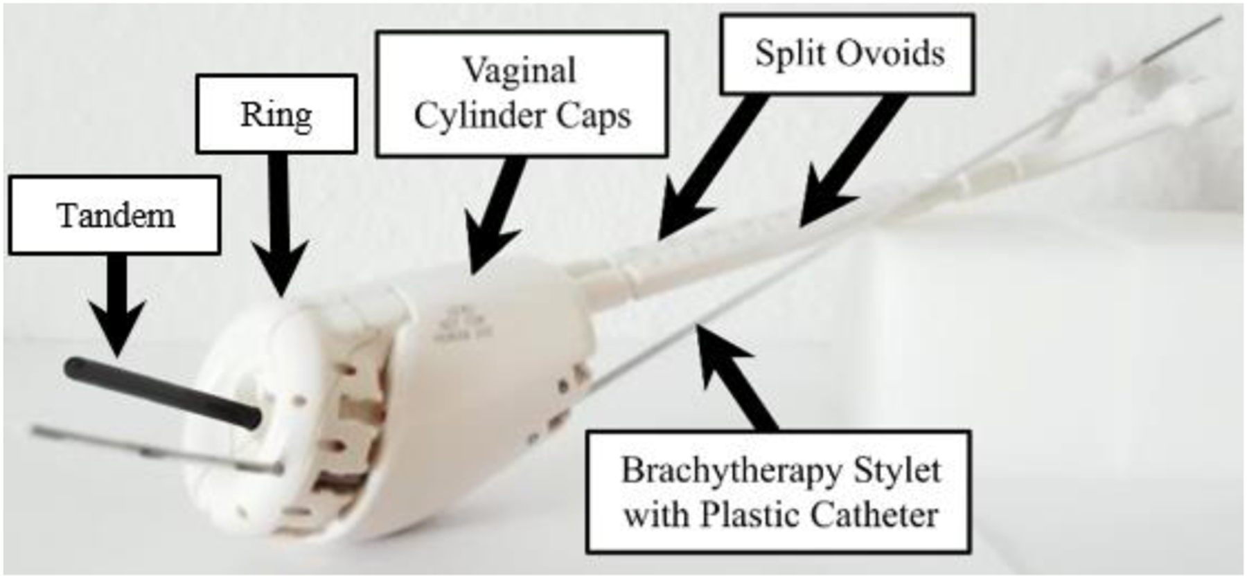
The Venezia gynecological applicator (Elekta, Sweden) depicts an interstitial catheter, which will be advanced through the cervix [10].
Conventional methods to track the stylet locations inside the tissue involve the use of intraoperative imaging modalities such as X-ray, computed tomography (CT), ultrasound (US), or Magnetic Resonance Imaging (MRI) [9, 11, 12]. However, X-ray and CT cannot be delivered continuously due to the radiation involved, while MRI methods suffer from a slow update rate, and US provides insufficient localization accuracy. Additionally, none can provide millimeter-level precision stylet localization at a temporal rate of several frames per second. In prior work, we implemented and validated active MR-tracking (MRT) for brachytherapy. MRT demonstrated significant improvement in terms of procedural time (~15 minutes with MRT vs ~56.2 minutes obtained with US guidance [9, 13–16]). However, accurate advancement of the metallic stylet to the target, necessary for further procedure acceleration, was still lacking. Multiple in-and-out stylet manipulations were necessary to correct deviations in catheter trajectory, which increased procedure durations and tissue disruption.
Current stylet control is limited to a single degree of freedom (DoF) in that it can only be linearly inserted/retracted. As such, the trajectory planning for a given target is defined by choosing the hole in the guidance tool that the clinician feels best counteracts the effects of tissue anisotropy. However, current guidance tools have predefined channels (see Fig. 1), which lead to inaccurate stylet placement due to the inherent mechanical resolution. Preliminary work indicated that MR-tracked stylets inserted toward targets with insertion depths between 35 and 172 mm using iterative coarse and fine repositioning methods (pulling out and then reinserting with a median of 15.50 mm), could only achieve a localization error of 11.10 mm and 4.10 mm, respectively [9].
In this study, we hypothesize that gynecological cancer brachytherapy treatment will have improved targeting accuracy if a deflectable stylet is integrated with the MR tracking technique, which will, in turn, reduce tissue damage and the procedure time, and reduce radiation injury to neighboring normal tissues. Deflecting an interventional device within the tissue to hit the target location can be achieved with several approaches, such as concentric tube robots [17], bevel-tipped steerable needles [11, 18], and tendon-driven mechanisms [19]. To fit seamlessly into the current workflow and gain the acceptance of the interventional oncologists, we applied a manually actuated tendon-driven mechanism to perform the stylet deflection. Two MR-tracking coils were mounted on the distal end of the deflectable stylet to monitor its real-time position for closed-loop positional monitoring of the insertion process. Additionally, miniaturized resonant floating RF traps (MBaluns) were incorporated on the proximal end of the deflectable device to reduce the risk of tissue damage caused by MRI radio-frequency heating. The following paper is divided into four sections. Section II describes the design, fabrication and prototyping, modeling, and the MRT and MBaluns integration of the proposed deflectable stylet. Section III elaborates on the experimental setups and procedures. Section IV provides the experimental results and a discussion of the results. The paper concludes in Section V.
II. Methods
A. Design Requirements
To address the limitations associated with the conventional straight stylet delivery method, we aim to design a new stylet that could provide dexterous trajectory correction when the stylet is advanced from the guidance holes. The following requirements are considered during the design process. First, the new design should fit seamlessly into the current procedure workflow, as well as with existing MRT coils [8]. As such, the new deflectable stylet must fit within the brachytherapy catheter, which has an inner diameter (ID) of 1.45 mm. Second, the stylet must be MR-Conditional and super-elastic. The latter characteristic prevents plastic deformation of the stylet when force is applied. The stylet must also be able to deflect by at least 9°. This deflection angle is required so that the workspace between each guiding hole is fully covered. Finally, the deflecting region of the stylet must maintain enough rigidity to allow tissue puncture without buckling. Robot-assisted stylet deflection is not considered in the proposed work due to the intrinsic complexity to obtain future FDA clearance, but it can be seen as a natural extension of this work.
B. Deflectable Stylet Design and Fabrication
In our design, a nitinol tube (ID: 0.90 mm, OD: 1.40 mm, JM# 84742, Johnson Matthey, CA, USA) was used to create the deflectable stylet. Nitinol is a non-ferromagnetic material, permitting safe operation within the MRI environment, that also possesses super-elastic properties, providing strain recovery of up to ten percent [20, 21]. This hollow tube also allowed the placement of the nitinol tendon wire (OD: 0.25 mm, NW-0100, Component Supply, TN, USA) and the MRT micro-coaxial cables (OD: 0.15 mm, Precision Interconnect) within the internal channel. A Young’s modulus of 38 GPa and 42 GPa was used for the nitinol tube and tendon, respectively, based on the provided material datasheets. An upper plateau stress of 540 MPa and a lower plateau stress of −750 MPa was used for both the tube and tendon. The plastic brachytherapy catheter (ID: 1.45 mm, OD: 1.96 mm) had a Young’s modulus of 1.20 GPa with an upper and lower plateau stress of 85 and −90 GPa, respectively.
The MRT micro-coils were incorporated by machining two 12.70 mm long grooves axially along the distal end of the stylet at a cut depth of 0.76 mm. A flat region was produced for micro-coil placement by adding solder to the machined grooves of the nitinol tube, after which this region was machined flat for coil adhesion. This flat solder adhesion not only served as the flatbed for the micro-coil placement, but also as the attachment method for the tendon wire to the distal end of the nitinol tube. The detailed view representing the micro-coils’ placement is illustrated in Fig. 2A. To permit local deflection at the stylet’s distal end, four asymmetric cutouts were made axially along the stylet prior to the groove for the proximal MRT micro-coil, as seen in Fig. 2B. The asymmetric cutouts allowed unidirectional deflection when the tendon is retracted. These cutouts were 1.72 mm apart, 3.17 mm in length, and cut at a depth of 0.76 mm. It should be noted that the cutouts for deflection were intentionally cut on the opposing side of the tube that the MRT grooves were cut on. This reduced the possibility of damage to the micro-coaxial cables caused by tendon-wire actuation or tube deflection.
Fig. 2.
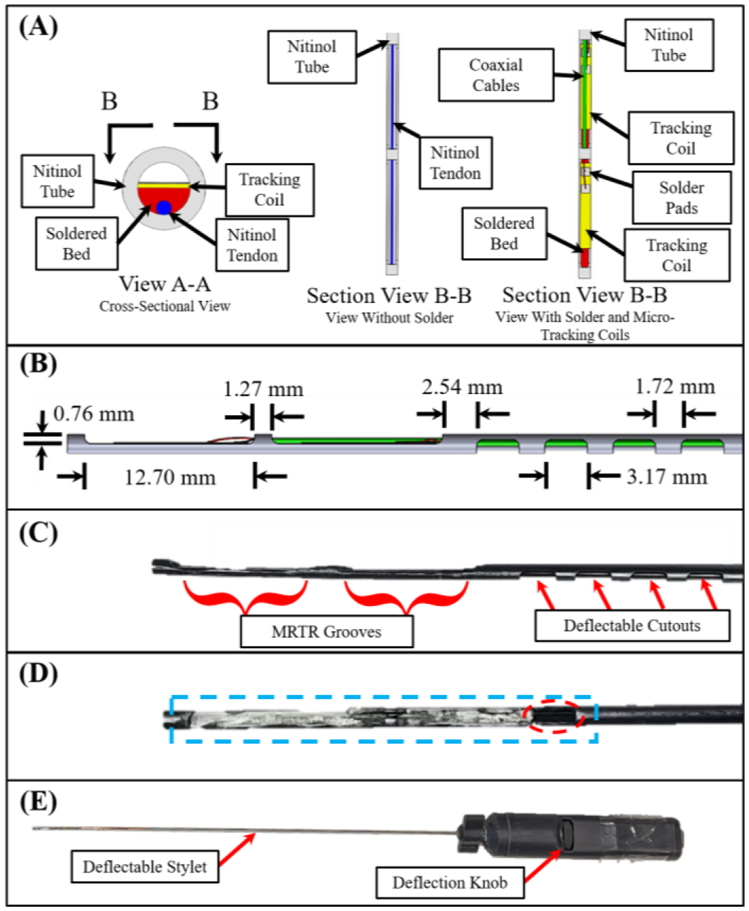
View A-A in (A) shows the solder bed (red), the nitinol tendon (blue), the MRTR coils (yellow), and the nitinol tube used as the brachytherapy stylet (grey). Section View B-B provides a downward looking view of the same assembly, without the solder (left), and with the solder, tracking coils, and micro-coaxial cables (right). (B) Side view of the stylet with the corresponding dimensions. (C) The stylet following the machining operations. (D) Stylet after machining the soldered surface flat (blue). Note the gap left to provide access for the micro-coaxial cables (dotted red ellipse). (E) Full handle assembly after assembly.
In this study, a four-flute, 45°, ⅛-inch carbide end mill was used (SKU 415–1502, Shars Tool, IL, USA) to create the grooves for the micro-coil placement (milling machine: Bridgeport 1.5 HP). The cutouts of the deflectable section were fabricated with the same end mill. The tendon wire was soldered to the nitinol tube using Indalloy solder #12 (96.5Sn 3.5Ag, 0.030in solder wire) and Indium Corporation Flux #2. The prototype can be seen in Fig. 2C–E. Following the machining and soldering operations, the micro-coils were fixed to the machined soldered flat beds using fast curing adhesive. Micro-coaxial cables (OD: 0.15 mm) were then soldered to the micro-coils and guided through the nitinol tube. One unique characteristic of using a tube as compared to a solid stylet [8] involved the ability to store excess length (~1–3 mm) of micro-coaxial cables within the tube. This allowed the cables to accommodate extension when the stylet undergoes deflection, preventing unwanted stress to the solder joints between the coaxial-cables and the micro-coils.
C. Kinematic Modeling
In this section, we aim to develop the kinematic model that relates the desired stylet tip pose to the joint-space tendon wire retraction. The modeling in this paper is the extension of prior work [22–24] with the primary contribution pertaining to the consideration of tendon wire elongation during the actuation process. Fig. 3 depicts the stylet subjected to tendon retraction and the corresponding geometry. The transformation matrix that describes this geometry from the base frame to the desired target location can be defined as:
| (1) |
Fig. 3.
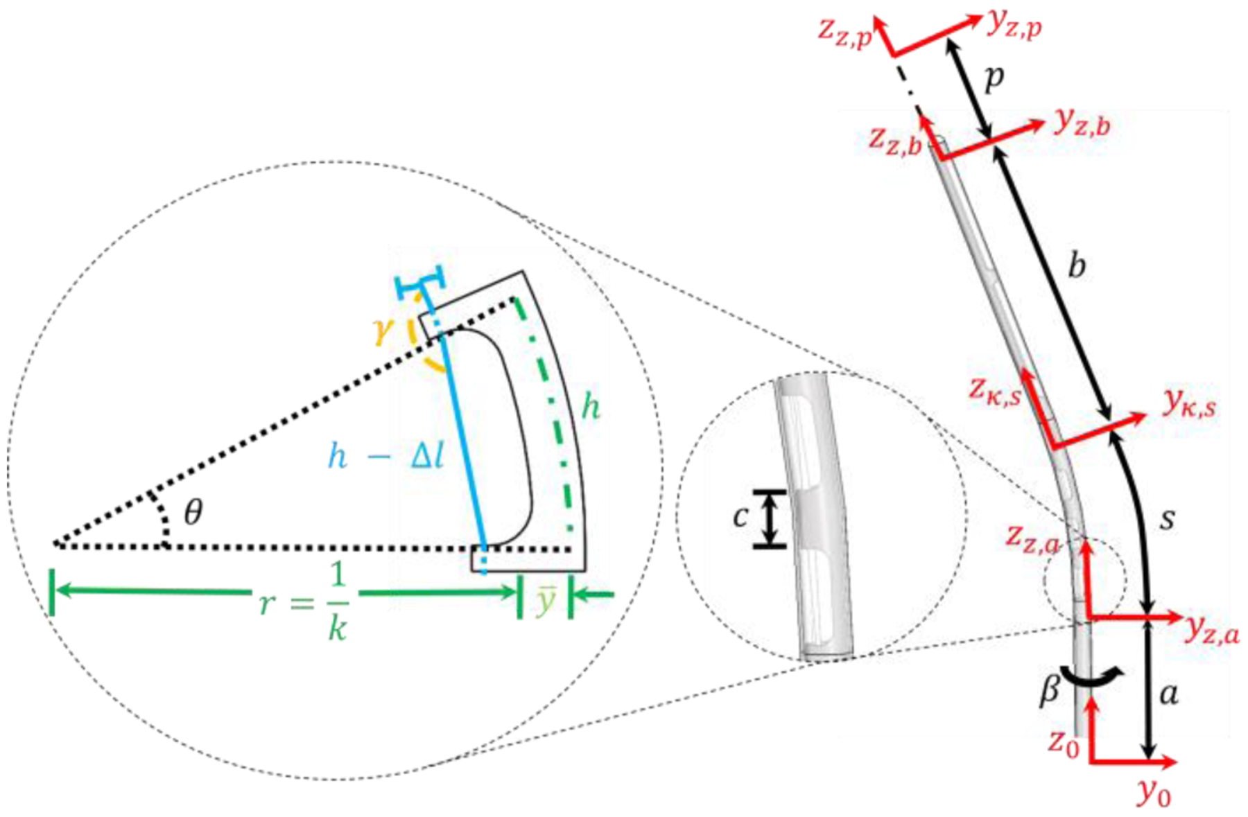
A single cutout being deflected and its corresponding geometry is depicted to the left based on tendon retraction. Blue is the tendon, the dashed green line is the location of the neutral bending plane, and the black dashed lines depict the change in the deflection angle. A side view (right) of the stylet is also given. The catheter surrounding the stylet is transparent. Additionally, the location of location coordinate frames can be seen in red.
The transformation matrix from the base frame to the first cutout Tz,a is defined by the following equation:
| (2) |
where a is the distance from the base frame to the first cutout and β is the rotation around the longitudinal axis of the stylet. The angle β plays a critical role in trajectory planning, where rotation of the stylet can change the insertion trajectory.
The transformation matrix of the whole deflection region, as discussed by [22], is shown in (3).
| (3) |
where the arc length s and the curvature κ of the deflectable region can be defined by:
| (4) |
| (5) |
where n is the number of cutouts, ℎ is the cutout width, c is the spacing between the cutouts, is the neutral bending plane, and θ is the desired deflection angle of the deflectable tip as shown in Fig. 3. The kinematic relationship between tendon retraction within the deflection region Δl and the stylet curvature κ can be found in (6) [22, 24].
| (6) |
where ri is the inner radius of the tube. This equation will be leveraged in the following section.
From Fig. 3, it is apparent that two additional transformation matrices are needed: (i) a transformation matrix from the last cutout to the tip of the stylet, and (ii) a transformation matrix to account for insertion depth. The transformation matrix from the last cutout to the tip of the stylet can be defined by:
| (7) |
where b is the distance from the last cutout to the tip of the stylet. The transformation matrix to account for insertion depth is described by (8), where p is the insertion depth.
| (8) |
Note that equation (8) is developed based on the assumption that the stylet travels in a straight line to reach the target. This assumption will be systematically validated in Section IV-B.
To solve the inverse kinematics, the joint space variables, κ, β, and p, were solved using the desired target location in the robot coordinate frame and the deflectable stylet design parameters a, b, and s. κ was solved numerically by driving the left-hand side of (10) to equal zero using the fsolve function in MATLAB. β and p were obtained analytically. The relationships between the three unknowns to the three knowns are shown below:
| (9) |
| (10) |
| (11) |
where [xd, yd, zd] are the target locations with respect to the robot coordinate frame.
D. Force Analysis
It was noticed that the tendon-wire elongation is non-negligible when an axial load is applied to the thin nitinol wire, which had a diameter and length of 0.25 mm and 30 cm, respectively. This was not considered in previous studies [22, 24]. In this section, we aim to develop a force model that accounts for the tendon wire elongation, and predicts the accurate tendon retraction and force necessary to reach a desired target.
A critical design limitation is that the stresses in the tendon wire must remain below the upper plateau stress of the tendon’s material properties. If the upper plateau stress is exceeded, any additional tendon retraction will only result in increased strain in the tendon, with no additional load applied for stylet deflection. As a result, a derivation for the elongation strain of the tendon is a linear relationship provided in the following equation:
| (12) |
where FT is the force in the tendon, AT is the cross-sectional area of the tendon, and E is the Young’s modulus of the tendon. FT can be found using a strain energy based method, which can be written as:
| (13) |
where U is the total strain energy stored in the system, θ is the deflection of the system, F is the force applied to obtain the deflection, and L is the moment arm [22, 24]. In this case, the total strain energy is the sum of its constituents as described by (14).
| (14) |
where UT,κ, Uc,κ, and Us,κ are the strain energies associated with bending in the tendon, catheter, and a single cutout of the deflectable stylet, respectively. UT,elong is the strain energy in the tendon associated with axial elongation, which is the primary contribution of this work. It should be noted that although UT,elong is not directly related to θ, it is a function of the tendon force, which is a function of θ. As a result, this equation can be applied if the partial of the total strain energy of the system with respect to θ is solved using a backward finite difference method with all initial conditions equal to zero.
To solve for the strain energy associated with elongation stored in the tendon, it is first recognized that the strain energy density is equal to the area under the stress-strain curve of a single axial fiber, as shown in (15).
| (15) |
where W(ε) is the strain energy density as a function of strain and σ is the stress. As a result, the strain energy caused by tendon elongation can be defined as:
| (16) |
where Lt denotes total tendon length from the end of the solder joint to the control handle and ro is the radius of the tendon.
Considering friction between the tendon wire and each non-cutout region, the force in the tendon can be written as [22, 24]:
| (17) |
where η is a lumped term [22, 24], μ is the coefficient of friction, and γ is deformation angle shown in Fig. 3. Combining (6), (12), and (17), the total tendon retraction needed to accurately reach the desired target can now be written as:
| (18) |
where n is the number of cutouts in the stylet, Δl is the tendon retraction necessary to satisfy equation (1) through kinematic analysis, and the second term is the retraction necessary to account for tendon elongation from the strain.
E. MRI-Tracking
MR-Tracking was accomplished using two micro-coils made of a 3-layer flexible-printed-circuit (FPC). The coil had the length, width, and thickness of 8 mm, 1.10 mm, and 0.20 mm, respectively. Tracking coil tuning and matching was achieved using embedded thin-film capacitors, providing a 63.8 MHz resonance and a (S11) reflection coefficient of approximately - 20dB, as seen in the lower images of Fig. 4. The specifics of the micro-coil tuning circuit design can be found in [8]. The circuitry used for tuning and matching was contained in the proximal end of the handle assembly next to the LEMO connector used for signal transmission, as seen in the upper image of Fig. 4.
Fig. 4.
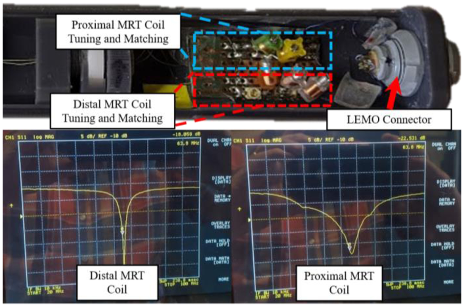
The upper image is the proximal end of the handle assembly, which contains the tuning and matching circuits for the proximal and distal MR-Tracking coils. The lower images are the S11 plots of the distal and proximal MRT coils, as seen on a Vector Network Analyzer, after tuning and matching the circuitry. The resonance occurred at 63.8 MHz (the Larmor frequency of the Siemens 1.5T scanner).
F. MBalun Integration
The MBalun winding was integrated into the proximal end of the stylet to avoid potential heating of the metallic stylet caused by standing waves during high Specific-Absorption-Rate (SAR) MRI pulse sequences [25]. 96 windings of 38 AWG copper wire were wound around a Mylar tube (ID: 1.58 mm, OD: 1.98 mm) using an automated wire-winding machine. The Mylar tube acted as an insulating sleeve. A winding pitch, defined as the ratio of the distance between successive windings to the bare wire diameter, of 3 was used. At the distal end of the “solenoid”, the wire was attached to the nitinol tube using silver epoxy. The proximal solenoidal wire end was soldered to an 8.2 pF tuning capacitor, which was thereafter electrically connected to the nitinol tube using silver epoxy. As a result of the inductor-capacitor series resonant circuit, the MBalun forms a robust barrier to electrical common mode propagation at 63.8 MHz.
III. Experimental Setup and Procedure
A. Model Validation
The kinematic and force analysis models were validated by constructing an experimental setup that simultaneously measured force and tendon retraction. This was achieved using a linear sliding table incorporating an SFU1605 ball screw driven by a NEMA 23 stepper motor as shown in Fig. 6. The tendon wire was attached to a force sensor (Go Direct® Force and Acceleration Sensor, Vernier), which was constrained to the linear table. The deflectable stylet assembly was fixed to the end of the linear rail using a brass collet. A camera (5WH-00002, Microsoft LifeCam Web Camera) was placed perpendicular to the longitudinal axis of the stylet to obtain the stylet shape. The camera was calibrated using the MATLAB Camera Calibration Toolbox [26]. The tendon wire was retracted from 0 to 5 mm in 0.20 mm increments. At each increment, the force measured from the Vernier force sensor was recorded in conjunction with an image of the stylet being taken.
Fig. 6.

Experimental setup for the force model validation test. Note that the background is white and the plastic catheter was darkened to work seamlessly with the MATLAB image processing techniques.
B. Targeting Test
The targeting test was conducted in both an agar phantom and a porcine tissue sample. The agar phantom was a 2.5% mixture according to the method described in [27]. The experimental setup, as shown in Fig. 7, consisted of the same system used in the kinematic model validation experiment; however, in this case, the linear table constrained a custom-designed handle that retracted the tendon based on the rotation of a knob at the base of the handle (see [28] for the control handle working principle). The stylet tip trajectory was recorded by Electro-Magnetic (EM) tracking coils (Aurora, NDI Medical, Ontario, Canada), which were placed at the MRTR grooves (see Fig. 2C) with the cables routed within the inner channel of the nitinol stylet. The recorded position data points were converted to the deflectable stylet coordinate frame using rigid body transformation methods [29]. Note that bending occurs in the negative y-direction per the coordinate system shown in Fig. 7, which is consistent with Fig. 3.
Fig. 7.
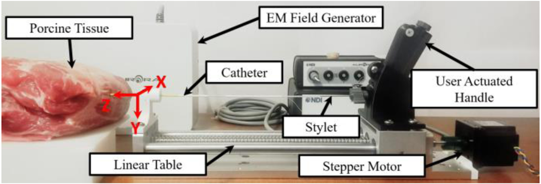
The experimental setup for the trajectory test in the porcine tissue is depicted above. The location and orientation of the robot base frame can be seen. The z-axis is in line with the stylet pointing toward the direction of insertion and the y-axis is orientated downwards. The stylet trajectory was obtained with an EM tracker.
There were three tests associated with the targeting test. The first test was used to determine if trajectory changes could be made while the stylet was in the tissue. This was systematically validated by inserting the stylet with a deflection of 0° until the entire deflectable region of the stylet was inside the agar phantom. The stylet was then inserted 60 mm (the typical stylet insertion depth observed in our prior human trials) with 0 mm tendon retraction while the trajectory was recorded. The stylet was then moved to a new position and reinserted to the same initial insertion depth (60 mm). The tendon retraction was then set to 5 mm and the stylet was inserted 60 mm. Both trajectories were recorded for a comparative study.
The second test was used to investigate the trajectory obtained from a known initial deflection angle. This was accomplished by retracting the tendon to obtain an initial configuration angle, placing the stylet tip coincident with the surface of the phantom and then inserting the stylet 60 mm while recording the trajectory. The desired tendon retraction for an initial stylet deflection was determined by the force model validated in the previous section. The initial configuration angle was varied from 0° to 13°.
The third test was the targeting test used to determine the accuracy of the proposed modeling method. This was accomplished by inserting the stylet into the porcine tissue with calculated joint-space parameters to reach pre-defined target locations within the porcine tissue.
C. MRI-Guided Navigational Test
The MRT was tested while attached to the device in a Siemens 1.5T Espree MRI scanner. STIR-UTE sequencing was implemented using TI/TR/TE/θ= 120ms/20ms/60us/10°, with a resolution of 0.9×0.9×1.8mm3. This was accomplished by setting up a cubic phantom made of a gel phantom (gel conductivity = 0.6 S/m, gel relative dielectric constant = 77), within the MRI. The device was then inserted into the gel by a clinician at 10 different arbitrary deflection angles ranging from 0° to 11°. The MR-Tracking coils were then scanned and the image was analyzed to determine if the coils were effective at indicating position.
The effectiveness of the MBaluns was evaluated by taking measurements of temperature increases in the vicinity of the MBalun-equipped brachytherapy stylet according to ASTM Standard F2182–11a [30]. The device was inserted 20 cm into an ASTM gel phantom (gel conductivity = 0.6 S/m, gel relative dielectric constant = 77) in the bore of a Siemens 1.5T Espree MRI Scanner. The device was oriented parallel to the z-axis, with the shaft displaced from the magnetic field center by 10 cm in the Left-Right direction, and the tip displaced 40 cm from the magnetic field center in the Superior-Inferior direction, placing the tip in a region of maximal induced electric field. The device was scanned for 15 min with a 4.0 W/kg Specific Absorption Rate Steady State Free Precession (SSFP) sequence (Repetition-time)/ Echo-time/ Flip-angle = 2.5 ms/1.3 ms/66°, Bandwidth = 977 Hz/pixel, field of view = 40 × 40 cm2, matrix = 128 × 128). The temperature was measured using a fiber-optic temperature probe (Neoptix RF-04- 1, Montreal, Canada) placed beside the stylet’s most distal MRT micro-coil. The temperature of a reference point far from the device was also collected in order to account for temporal temperature changes in the gel.
A control was provided by measuring the temperature increase of the device without MBaluns using an identical setup. Baseline temperatures were also recorded before Radio-Frequency transmission, and temperature changes were measured during the scanning.
IV. Results and Discussion
A. Model Validation
Using the experimental setup and procedure discussed in Section III-A, ten experiments were conducted of tendon retractions ranging from 0 to 5 mm at 0.2 mm increments, resulting in 260 data points. In Fig. 9A, the stylet tip locations can be seen with respect to the base frame, where increasing tendon retraction corresponds to a counter clock-wise progression. Note that at low stylet deflection angles, the model accurately predicts the position of the tip position; however, with increasing angle, the experimental results slightly diverge from the model. Nonetheless, the model can achieve sub-millimeter precision (<0.5mm) throughout all the tests, which is within the resolution of the MR images (1mm/pixel).
Fig. 9.
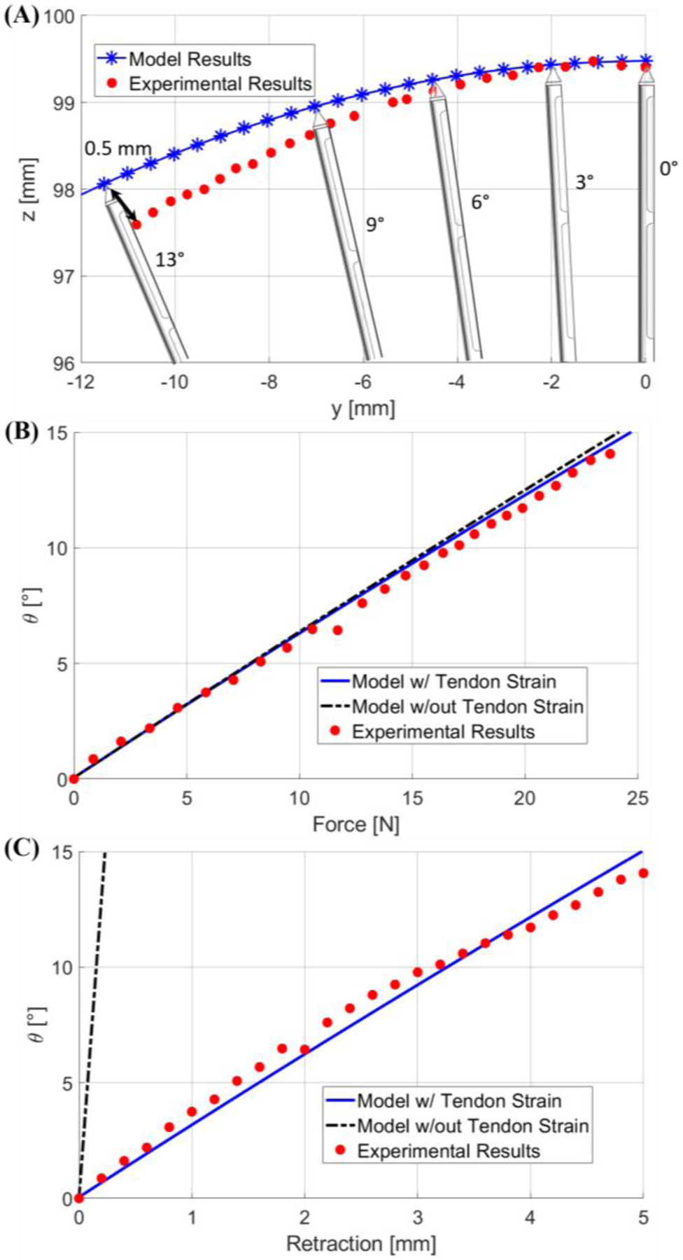
(A) is a plot of the stylet tip position when deflection angle increases from 0 to 13 degrees. (B) and (C) are plots of the stylet bending angle calculated by the two models with respect to force and tendon retraction, respectively. Note that previous model is indicated by the black hyphenated lines, whereas our model is indicated by the blue lines.
Fig. 9B depicts a comparison of the measured average force to the force computed by the numerical model with respect to the configuration angle of the stylet. Note that each data sample in Fig. 9B was repeated 10 times in order to obtain statistically significant results. Here we use the bending angle θ as the configuration variable. It was found that our model predicted better results with an error of 0.18±0.15°. In the case of the highest applied force, and error, of 23.75 N, our model predicts an angle of 14.43°, whereas the previous models predicts an angle of 14.89°, and the experimental results indicate an angle of 14.05°. Our model, which includes the strain energy of the tendon, indicates that a given force would generate a lower deflection angle when compared to the previous model. This trend is clearly indicated in Fig. 9B.
Fig. 9C depicts a comparison of the experimentally measured and theoretically calculated tendon retraction with respect to the bending angle θ. The proposed force model demonstrated a significantly improved prediction accuracy for tendon retraction, as compared to the previous models [22, 24], with an error of 0.46±0.24°. For example, at a bending angle of 14.05°, our model predicts a tendon retraction of 4.67 mm and the previous model predicts a tendon retraction of 0.22 mm, which leads to an error of 0.32 mm and 4.78 mm, respectively. This comparison highlights the paramount importance of accounting for tendon elongation, particularly in this application where the total tendon wire length is 390 mm. Potential causes for error using our proposed model can be the unaccounted strain in the system, such as strain in the mounting rod for the force sensor, and strain in the mounting of the stylet.
B. Targeting Test
The first phantom test was conducted ten times to ensure the results were statistically significant. It was observed that there were no substantial deviations (<1mm trajectory change as shown in Fig. 10A) in a trajectory when the tendon retraction was applied while the deflectable region was already inside the tissue (see Fig. 10A for the trajectories obtained in both scenarios). This can be explained by the counter moment applied by the surrounding tissue to the distal end of the stylet. This observation is critically important as it guarantees the trajectory cannot be changed with tendon retraction after the deflectable region is inserted into the tissue. Thus, the deflection of the stylet should be applied before deploying it into the tissue.
Fig. 10.
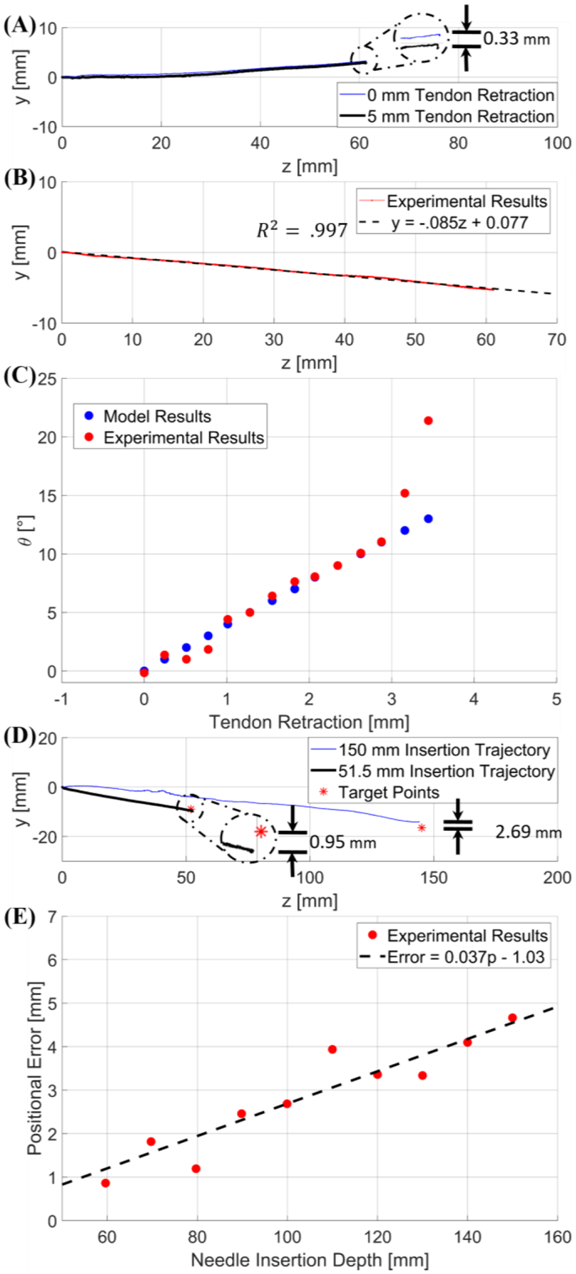
(A) is a graphical representation of the comparative study between a trajectory with 0 mm tendon retraction and a trajectory with 5 mm tendon retraction applied when the deflectable region is already inside the tissue. The error is depicted in the detailed view. (B) provides an example trajectory at a 5° user input, indicating a linear trajectory. (C) is a graph of the results from the second targeting test; blue represents the deflection angle vs. tendon retraction model per the modeling method in free space discussed in Section IV-A, and in red are the inclination angles of the experimental trajectories resulting from the corresponding tendon retraction. (D) provides two different trajectories within the porcine tissue with respect to their desired target locations (red asterisk). The 150 mm trajectory was obtained with initial deflection angle of 6.41° (blue line), and the 51.50 mm trajectory was obtained with initial deflection angle of 9.28° (black line). (E) is a graphical relationship between positional error and insertion depth within the porcine sample.
The results of the second test can be seen in Fig. 10B–C with each data sample being repeated 5 times. These tests provided evidence that the insertion trajectory is collinear with the initial deflection angle of the stylet, which indicates that the trajectory can be approximated as a linear line with the gradient equal to tan( θ ), as shown in Fig. 10B. Depicted in Fig. 10C is a comparison between the angle of the stylet with respect to the kinematic model based on a tendon retraction in free space and the angle of the trajectory in the phantom resulting from the same tendon retraction. Note that the mean error is 0.35°±0.37° if the deflection angle is less than 11°; however, the trajectory angle diverges significantly from the initial stylet angle when the initial configuration angle is larger than 11°. This can be explained by the reaction force applied by the tissue to the tip of the stylet during initial insertion. Thus, the kinematics and mechanics model developed above can be applied for trajectory planning if the initial deflection angle is less than 11°.
The targeting test was conducted for twenty arbitrary targets in the agar phantom and twenty-five targets in the porcine tissue. The target locations varied in insertion depth from as low as 40 mm to as high as 150 mm. The input angle varied from 0° to 10.50°. In the agar test, the average error was 1.23± 0.47 mm. In the porcine test, when the insertion depth was 60 mm or less, the average error was 1.65±0.64 mm. For insertion depths of 150 mm into the porcine tissue, the average positional error was 3.21±1.12 mm. Note that an insertion depth of 60 mm was typically observed in our human trials. An example of the resulting trajectories can be seen in Fig. 10D.
The results of these tests illustrate the effectiveness of this device; the accuracy in this work with a single insertion is significantly improved compared to previous studies involving multiple retracting-and-reinserting manipulations [9]. The primary contribution to targeting error is due to the different tissue properties in the trajectory, such as fat, muscle, and elastin. In instances where large errors occurred (>5mm) in the deep insertion trajectories, the stylet was inserted into regions that possessed different tissue structures. In instances where the errors were low (<1.5 mm), long sections of muscle were found and used for the test. In general, the positional error increases with insertion depth due to the increased likelihood of traversing tissues with differing elastic properties, as well as cavities or gaps in the tissues [31–33]. This is illustrated in Fig. 10E, where a target location was intentionally selected such that the angle was the same (7.84°), but the insertion depth was varied. For each target location, the stylet was completely removed and inserted into a new location, thus ensuring that the previously cut trajectory would not affect the validity of the data.
C. MRI-Guided Navigational Test
By comparing the ground truth location of the center of the MRT coil positions, as measured by high-resolution 3D MR images acquired by an inversion-recovery gradient echo (MP-RAGE) sequence with a spatial resolution of 0.3×0.3×0.3 mm3 to the MR-Tracking detected locations (MR-Tracking parameters: FOV of 300 mm, 512 pixels/projection, 3 averages, 4 phase-ditherings/projection) the MRI-guided navigational test indicated that the MR-Tracking sequence, provided the location of the stylet tip in the MRI reference frame at a rate of ~15 Hz with a precision of 0.6×0.6×0.6 mm3. An example of the scanned stylet within the MRI environment can be seen in Fig. 11. Use of the MBaluns was successful at reducing the temperature to FDA approved levels. The control device without MBaluns resulted in a temperature increase of 2.5±0.1 °C. When the device was equipped with the MBaluns, the temperature increase was 1.8±0.1 °C, which was within the acceptable limits (2°C requirement [34]). Additionally, the tracking coils were easily identified in Turbo Spn Echo MRI images obtained within a prostate phantom, based on their hyperintensity ratio of >5:1 relative to the tissue voxel intensity, with the artifact produced by the stylet extending for less than 2 mm from the metallic surface.
Fig. 11.
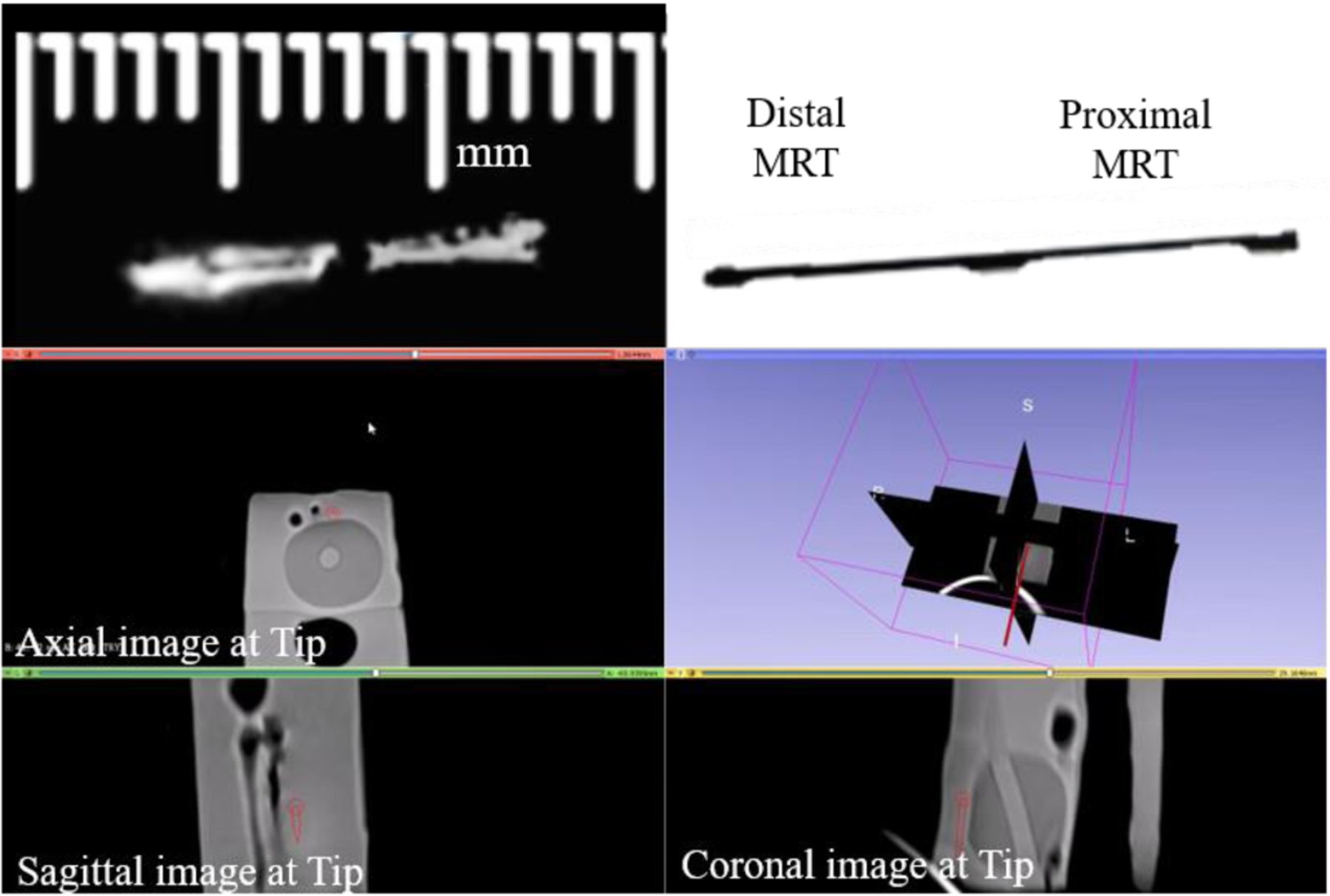
A side by side comparison can be seen of the tracking coils on the stylet scanned within a prostate phantom inside the MRI environment (left), next to an image of the stylet (right) obtained at the same configuration. The lower image is a 3D Slicer view depicting the instantaneous stylet tip location and orientation (dark red line) during navigation in a prostate phantom. The tip is linearly extrapolated from the locations determined from the MR-Tracking provided by the MRT coils.
V. Conclusions
This paper presents the design and fabrication, mechanics modeling, and trajectory planning validation for a deflectable stylet used in interstitial brachytherapy. The stylet was made of the super-elastic nitinol, and the actuation method to induce deflection was tendon retraction. Our kinematic model was able to determine the tip location within 0.50 mm in the free space conditions. The force model was able to predict the bending angle with a mean error of 0.18°± 0.15°. The corresponding tendon retraction model was able to accurately predict the stylet deflection angle for a given tendon retraction displacement with a mean error of 0.46°±0.24°. Experimental results indicated that the trajectory cannot be manipulated when the deflectable region of the stylet was within the tissue. Also, it was found that the trajectory of the stylet is collinear with the initial deflection angle. Using the collinear assumption, the kinematics model developed in free space could accurately determine the joint-space parameters necessary to reach a target location in the tissue. The model was then validated in a porcine tissue sample and obtained the targeting results with a mean error of 1.65±0.64 mm. MRI experiments indicated that the stylet could be tracked with a rate of ~15 Hz with a precision of 0.6×0.6×0.6 mm3. Additionally, the MBalun was successful at ensuring the safety of the device while being used in the MRI by reducing the temperature change during peak-SAR imaging to 1.8°C.
Our future work will involve systematically analyzing the sources of error in placement of the deflectable stylet inside ex-vivo tissue. Following error characterization, we will evaluate the effectiveness of delivering the brachytherapy seeds to a desired target location in animal trials in the MRI. Finally, we will conduct a patient trial to test the efficacy of this prototype in an actual bracytherapy catheter placement procedure. The efficacy of the proposed active deflectable stylet relative, to existing non-deflectable active stylets [6], will be evaluated in human clinical trials, where multiple (10–20) catheters are inserted, based on (i) the mean procedure duration per catheter, (ii) the mean number of (in and out) insertions required to reach a catheter’s desired target, and (iii) the mean targeting error relative to the clinician’s initial desired catheter location.
Fig. 5.

An MBalun, which had a resonance frequency of 63.8 MHz, can be seen attached to the proximal end of the nitinol deflectable stylet.
Fig. 8.
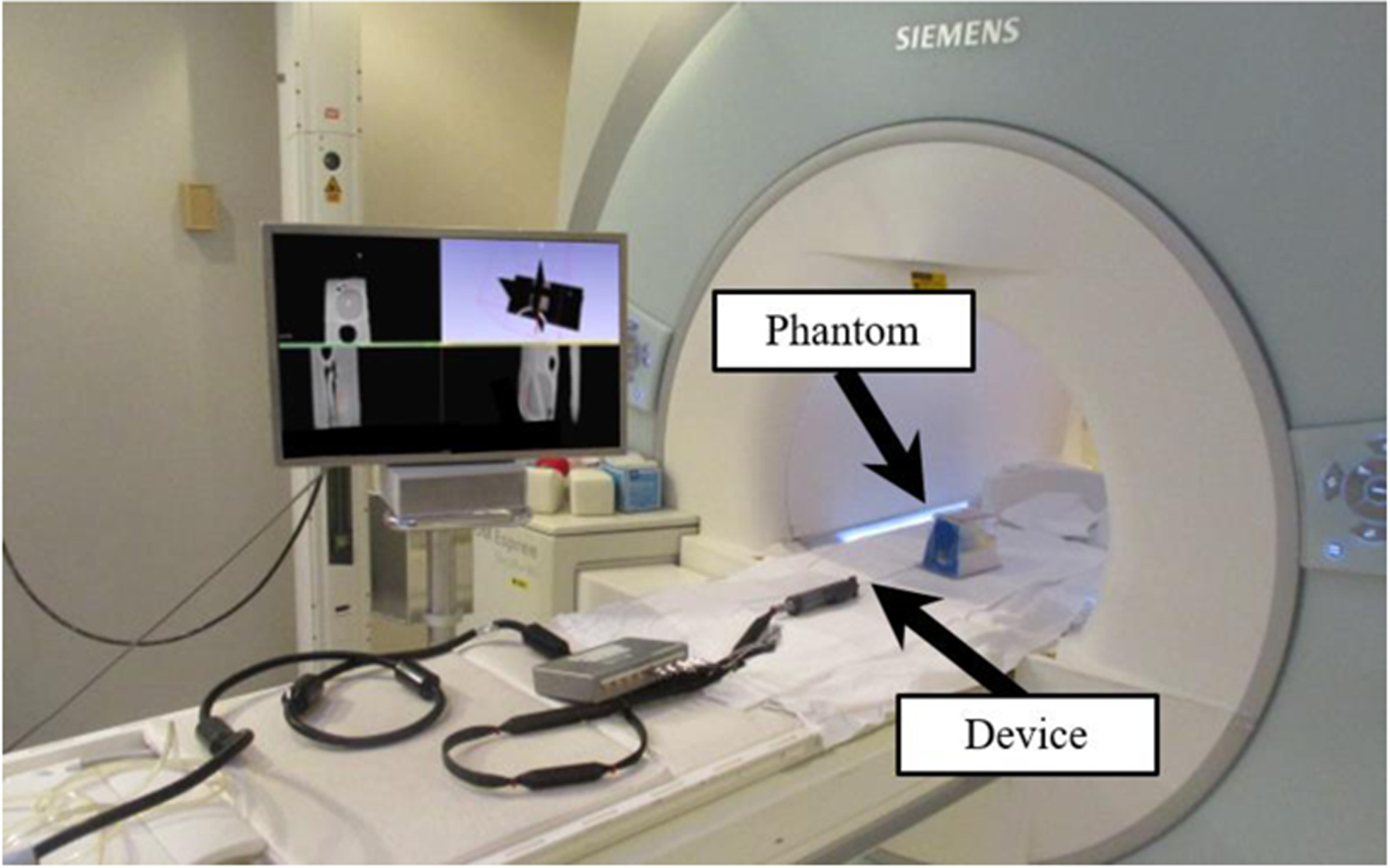
Experimental setup inside Siemens 1.5T Espree MRI scanner for the MRI-guided navigational test, with deflectable stylet assembly and prostate phantom depicted in the MRI.
Acknowledgment
The authors would like to thank Ben Fleming, Jason Bailey, and Monty Roberts for their advice on machining fixtures and soldering.
This research is supported by R01-HL094610, R01-HL126092, and R21CA167800.
Biographies

Anthony L. Gunderman was born in Batesville, AR, USA in 1997. He received a B.S. in mechanical engineering from the University of Arkansas, Fayetteville, AR, USA in 2019. He is currently pursuing a PhD in mechanical engineering at the University of Arkansas, Fayetteville, AR, USA.
In 2017 and 2018, he participated in two cooperative education stints with L3-Technologies as a Design Engineer. Since 2019, he has been conducting research in medical robotics with Dr. Yue Chen in the Mechanical Engineering Department at the University of Arkansas, Fayetteville, AR, USA.
Mr. Gunderman is a member of the mechanical engineering honor society Pi Tau Sigma. Additionally, he is a national member of ASME.

Ehud J. Schmidt received his PhD from Stanford University in 1987 in Applied Physics. He currently works at Johns Hopkins Medicine as an associate professor of Medicine (Cardiology) and of Radiation Oncology and Molecular Imaging. His primary focus is research, including the areas of MRI-compatible devices, MR Imaging and MR Tracking pulse sequences, as well as MRI-guided cardiac electrophysiology. Ehud has engaged in MRI-guided interventions from 1998, advancing procedures from large-animal trials to humans in brain-tumor excision, abdominal-tumor radio-frequency and cryogenic ablation, pelvic tumor high-dose-rate (HDR) interstitial radiation therapy, and most recently anterior cervical-spine discectomy and fusion (ACDF).

Marc Morcos finished his residency in 2013 at McGill University in Radiation Oncology Physics. He is currently the director of Brachytherapy Physics at Johns Hopkins Medicine. He specializes in intensity modulated brachytherapy, radiopharmaceutical therapy, real-time motion management, radiochromic film dosimetry and Monte Carlo-based radiation dose calculations.

Junichi Tokuda received his B.S. in engineering, his Master’s degree in Information and Science Technology, and his PhD in Information and Science Technology from the University of Tokyo. He is currently an Associate Professor of Radiology at Brigham and Women’s Hospital and Harvard Medical School. His research interests include surgical navigation software, MRI-compatible robots, and integration of these technologies for clinical applications. He has broad experience of developing and testing image-guided software and manipulators clinically including navigation software and needle-guide manipulators for MR-guided microwave ablation and MR-guided prostate biopsy/cryoablation.

Ravi T. Seethamraju received his B.S. degrees in Chemistry from the University of Madras and BioTechnology from Acharya Nagarjuna University, he received his Master’s degree in instrumentation engineering from Anna University, and he received his PhD in control systems from the Indian Institute of Technology in Madras. He has been in the field of MR for 20 years spanning several fields and specializations within MR over the years. As a collaborations manager for MR R&D, his primary objective is to foster research at customer sites using Siemens MRI Scanners, where he acts as a bridge between the customer and Siemens Healthineers.

Henry R. Halperin Dr Halperin received the B.S degree in physics with highest distinction from Purdue University, the M.A. degree in physics from the University of California, Berkeley, and the M.D. degree from Louisiana State University, New Orleans, Louisiana. He is currently a Professor of Medicine, Radiology and Biomedical Engineering at the Johns Hopkins Medical Institutions. He is the co-director of the Cardiovascular Imaging Center of Excellence. He serves on the editorial board of the journal Resuscitation, and is a past chair of the national American Heart Association Advanced Cardiovascular Life Support Subcommittee and a past member of the Emergency Cardiac Care Committee.

Akila N. Viswanathan earned her undergraduate degree at Harvard-Radcliffe College, her medical degree at the University Of Pittsburgh School Of Medicine, followed by her Master’s in Public Health and Master’s in Epidemiology at the Harvard School of Public Health. She completed a residency in radiation oncology at the Joint Center for Radiation Therapy at Harvard Medical School, where she served as chief resident. She is currently the director for Johns Hopkins Radiation Oncology and Molecular Radiation Sciences, and a professor of radiation oncology, gynecology/obstetrics and oncology for Johns Hopkins University School of Medicine.

Yue Chen (M’ 19) received the B.S. in vehicle engineering from Hunan University, Hunan, China, in 2010, M.Phil. in mechanical engineering from Hong Kong Polytechnic University, Hung Hom, Hong Kong, in 2013, and Ph.D. in Mechanical Engineering, Vanderbilt University, Nashville, TN, USA, in 2018. He started the assistant professor position in 2018 at the Department of Mechanical Engineering, University of Arkansas, Fayetteville, AR, USA. His current research interests include medical robotics and soft robots.
Contributor Information
Anthony L. Gunderman, Mechanical Engineering Department, University of Arkansas, Fayetteville, AR 72701 USA
Ehud J. Schmidt, Department of Medicine, Johns Hopkins University, Baltimore, MD., 21205
Marc Morcos, Department of Radiation Oncology, Johns Hopkins University, Baltimore, MD., 21205.
Junichi Tokuda, Department of Radiology, Harvard Medical School, Boston, MA., 02115.
Ravi T. Seethamraju, Siemens Healthineers Boston, Boston, MA, 02115
Henry R. Halperin, Department of Medicine, Johns Hopkins University, Baltimore, MD., 21205
Akila N. Viswanathan, Department of Radiation Oncology, Johns Hopkins University, Baltimore, MD., 21205
Yue Chen, Mechanical Engineering Department, University of Arkansas, Fayetteville, AR 72701 USA.
References
- [1].Sudhakar A, “History of Cancer, Ancient and Modern Treatment Methods,” Journal of cancer science & therapy, vol. 1, pp. 1–4, 2009. [DOI] [PubMed] [Google Scholar]
- [2].Street W, “Cancer facts & figures 2019,” Am Cancer Soc, vol. 76, pp. 4, 2019. https://www.cancer.org/content/dam/cancerorg/research/cancer-facts-and-statistics/annual-cancer-factsand-figures/2019/cancer-facts-and-figures-2019.pdf. [Google Scholar]
- [3].Halperin EC, Brady LW, Wazer DE, and Perez CA, Perez & Brady’s Principles and Practice of Radiation Oncology, 6th ed., Philadelphia: Lippincott Williams & Wilkins, 2013. [Google Scholar]
- [4].Chargari C, Deutsch E, Blanchard P, Gouy S, Martelli H, Guerin F, Dumas I, Bossi A, Morice P, Viswanathan A, and Haie-Meder C, “Brachytherapy: An overview for clinicians,” Ca-a Cancer Journal For Clinicians, vol. 69, no. 5, pp. 386–401, SEP 2019, 2019. [DOI] [PubMed] [Google Scholar]
- [5].Yamada Y, Rogers L, Demanes D, Morton G, Prestidges B, Pouliot J, Cohen G, Zaider M, Ghilezan M, and Hsu I, “American Brachytherapy Society consensus guidelines for high-dose-rate prostate brachytherapy,” Brachytherapy, vol. 11, no. 1, pp. 20–32, JAN-FEB 2012, 2012. [DOI] [PubMed] [Google Scholar]
- [6].Viswanathan A, Szymonifka J, Tempany-Afdhal C, O’Farrell D, and Cormack R, “A prospective trial of real-time magnetic resonance-guided catheter placement in interstitial gynecologic brachytherapy,” Brachytherapy, vol. 12, no. 3, pp. 240–247, MAY-JUN 2013, 2013. [DOI] [PubMed] [Google Scholar]
- [7].Ashida S, Yamasaki I, Tamura K, Shimamoto T, Inoue K, Kariya S, Kobayashe K, Yamagami T, and Shuin T, “Feasibility and early outcome of high-dose-rate Ir-192 brachytherapy as monotherapy in two fractions within 1 day for high-/very high-risk prostate cancer,” Molecular and Clinical Oncology, vol. 4, no. 5, pp. 789–793, MAY 2016, 2016. [DOI] [PMC free article] [PubMed] [Google Scholar]
- [8].Chen Y, Wang W, Schmidt EJ, Kwok K-W, Viswanathan AN, Cormack R, and Tse ZTH, “Design and fabrication of MR-tracked metallic stylet for gynecologic brachytherapy,” IEEE/ASME Transactions on Mechatronics, vol. 21, no. 2, pp. 956–962, 2015. [DOI] [PMC free article] [PubMed] [Google Scholar]
- [9].de Arcos J, Schmidt E, Wang W, Tokuda J, Vij K, Seethamraju R, Damato A, Dumoulin C, Cormack R, and Viswanathan A, “Prospective Clinical Implementation of a Novel Magnetic Resonance Tracking Device for Real-Time Brachytherapy Catheter Positioning,” International Journal of Radiation Oncology Biology Physics, vol. 99, no. 3, pp. 618–626, NOV 1 2017, 2017. [DOI] [PMC free article] [PubMed] [Google Scholar]
- [10].“Venezia™ Advanced Gynecological Applicator,” March 2020. https://www.elekta.com/brachytherapy/applicators/gynecological-brachytherapy-applicators/venezia-gynecological-applicator/.
- [11].Khadem Moshen, Rossa Carlos, Sloboda Ron, Usmani Nawaid, Tavakoli, and Mahdi, “Ultrasound-Guided Model Predictive Control of Needle Steering in Biological Tissue,” Journal of Medical Robotics Research, 2016. [Google Scholar]
- [12].Tanderup K, Viswanathan A, Kirisits C, and Frank S, “Magnetic Resonance Image Guided Brachytherapy,” Seminars in Radiation Oncology, vol. 24, no. 3, pp. 181–191, JUL 2014, 2014. [DOI] [PMC free article] [PubMed] [Google Scholar]
- [13].Viswanathan A, Erickson B, Gaffney D, Beriwal S, Bhatia S, Burnett O, D’Souza D, Patil N, Haddock M, Jhingran A, Jones E, Kunos C, Lee L, Lin L, Mayr N, Petersen I, Petric P, Portelance L, Small W, Strauss J, Townamchai K, Wolfson A, Yashar C, and Bosch W, “Comparison and Consensus Guidelines for Delineation of Clinical Target Volume for CT- and MR-Based Brachytherapy in Locally Advanced Cervical Cancer,” International Journal of Radiation Oncology Biology Physics, vol. 90, no. 2, pp. 320–328, OCT 1 2014, 2014. [DOI] [PMC free article] [PubMed] [Google Scholar]
- [14].Kim H, Houser C, Kalash R, Maceil C, Palestra B, Malush D, and Beriwal S, “Workflow and efficiency in MRI-based high-dose-rate brachytherapy for cervical cancer in a high-volume brachytherapy center,” Brachytherapy, vol. 17, no. 5, pp. 753–760, SEP-OCT 2018, 2018. [DOI] [PubMed] [Google Scholar]
- [15].Wang W, Dumoulin C, Viswanathan A, Tse Z, Mehrtash A, Loew W, Norton I, Tokuda J, Seethamraju R, Kapur T, Damato A, Cormack R, and Schmidt E, “Real-Time Active MR-Tracking of Metallic Stylets in MR-Guided Radiation Therapy,” Magnetic Resonance in Medicine, vol. 73, no. 5, pp. 1803–1811, MAY 2015, 2015. [DOI] [PMC free article] [PubMed] [Google Scholar]
- [16].Wang W, Viswanathan AN, Damato AL, Chen Y, Tse Z, Pan L, Tokuda J, Seethamraju RT, Dumoulin CL, and Schmidt EJ, “Evaluation of an active magnetic resonance tracking system for interstitial brachytherapy,” Medical physics, vol. 42, no. 12, pp. 7114–7121, 2015. [DOI] [PMC free article] [PubMed] [Google Scholar]
- [17].Chen Y, Poorman ME, Comber DB, Pitt EB, Liu C, Godage IS, Yu H, Grissom WA, Barth EJ, and Webster RJ III, “Treating Epilepsy via Thermal Ablation: Initial Experiments with an MRI-Guided Concentric Tube Robot,” in Proceedings of the 2017 Design of Medical Devices Conference, Minneapolis, Minnesota, USA, 2017. [Google Scholar]
- [18].Rucker D, Das J, Gilbert H, Swaney P, Miga M, Sarkar N, and Webster R, “Sliding Mode Control of Steerable Needles,” Ieee Transactions on Robotics, vol. 29, no. 5, pp. 1289–1299, 2013. [DOI] [PMC free article] [PubMed] [Google Scholar]
- [19].Fichera L, Dillon N, Zhang D, Godage I, Siebold M, Hartley B, Noble J, Russell P, Labadie R, and Webster R, “Through the Eustachian Tube and Beyond: A New Miniature Robotic Endoscope to See Into the Middle Ear,” Ieee Robotics and Automation Letters, vol. 2, no. 3, pp. 1488–1494, JUL 2017, 2017. [DOI] [PMC free article] [PubMed] [Google Scholar]
- [20].Stoeckel D, “Nitinol medical devices and implants,” Minimally Invasive Therapy & Allied Technologies, vol. 9, no. 2, pp. 81–88, MAR 2000, 2000. [DOI] [PubMed] [Google Scholar]
- [21].Stoeckel D, “Nitinol - A Material with Unusual Properties,” Endovascular Update, no. 1, pp. 1–8, 1998. [Google Scholar]
- [22].York PA, Swaney PJ, Gilbert HB, and Webster RJI, “A Wrist for Needle-Sized Surgical Robots,” in International Conference on Robotics and Automation, 2015, pp. 1776–1781. [DOI] [PMC free article] [PubMed] [Google Scholar]
- [23].Webster R, and Jones B, “Design and Kinematic Modeling of Constant Curvature Continuum Robots: A Review,” International Journal of Robotics Research, vol. 29, no. 13, pp. 1661–1683, NOV 2010, 2010. [Google Scholar]
- [24].Swaney P, York P, Gilbert H, Burgner-Kahrs J, and Webster R, “Design, Fabrication, and Testing of a Needle-Sized Wrist for Surgical Instruments,” Journal of Medical Devices-Transactions of the Asme, vol. 11, no. 1, MAR 2017, 2017. [DOI] [PMC free article] [PubMed] [Google Scholar]
- [25].Alipour A, Meyer E, Dumoulin C, Watkins R, Elahi H, Loew W, Schweitzer J, Olson G, Chen Y, Tao S, Guttman M, Kolandaivelu A, Halperin H, and Schmidt E, “MRI Conditional Actively Tracked Metallic Electrophysiology Catheters and Guidewires With Miniature Tethered Radio-Frequency Traps: Theory, Design, and Validation,” Ieee Transactions on Biomedical Engineering, vol. 67, no. 6, pp. 1616–1627, JUN 2020, 2020. [DOI] [PMC free article] [PubMed] [Google Scholar]
- [26].Zhang Z, “A flexible new technique for camera calibration,” Ieee Transactions on Pattern Analysis and Machine Intelligence, vol. 22, no. 11, pp. 1330–1334, NOV 2000, 2000. [Google Scholar]
- [27].Earle M, De Portu G, and De Vos E, “Agar ultrasound phantoms for low-cost training without refrigeration,” African Journal of Emergency Medicine, vol. 6, no. 1, pp. 18–23, MAR 2016, 2016. [DOI] [PMC free article] [PubMed] [Google Scholar]
- [28].Gunderman AL, Schmidt EJ, Viswanathan AN, Halperin HR, Tokuda J, Seethamraju RT, and Chen Y, “MR-Guided Tissue Puncture with On-Line Imaging for HighResolution Theranostics,” in International Symposium on Medical Robotics Georgia Tech, 2020. [Google Scholar]
- [29].Chen Y, Godage IS, Sengupta S, Liu CL, Weaver KD, and Barth EJ, “MR-conditional steerable needle robot for intracerebral hemorrhage removal,” International journal of computer assisted radiology and surgery, vol. 14, no. 1, pp. 105–115, 2019. [DOI] [PMC free article] [PubMed] [Google Scholar]
- [30].“Standard Test Method for Measurement of Radio Frequency Induced Heating On or Near Passive Implants During Magnetic Resonance Imaging, ASTM F2182–11a, 2011.”
- [31].Khadem M, Rossa C, Usmani N, Sloboda R, and Tavakoli M, “A Two-Body Rigid/Flexible Model of Needle Steering Dynamics in Soft Tissue,” Ieee-Asme Transactions on Mechatronics, vol. 21, no. 5, pp. 2352–2364, OCT 2016, 2016. [Google Scholar]
- [32].Yan K, Sing WN, Ling KV, Yu Y, Podder T, Liu T-I, and Cheng CWS, “Needle Steering Modeling and Analysis using Unconstrained Modal Analysis,” in The First IEEE/RAS-EMBS International Conference on Biomedical Robotics and Biomechatronics, Pisa, Italy, 2006, pp. 87–92. [Google Scholar]
- [33].Okamura A, Simone C, and O’Leary M, “Force modeling for needle insertion into soft tissue,” Ieee Transactions on Biomedical Engineering, vol. 51, no. 10, pp. 1707–1716, OCT 2004, 2004. [DOI] [PubMed] [Google Scholar]
- [34].FDA, “Establishing Safety and Compatibility of Passive Implants in the Magnetic Resonance (MR) Environment,” 2014.


