Abstract
There has been much research exploring the use of fiber Bragg grating (FBG)-sensorized needles in the prostate biopsy procedure, but all FBG needles used in the research need to be calibrated, which is time consuming and prone to human errors. In this work, a semi-automatic robotic system was developed to perform FBG needle calibration. Compared to manual calibration results, the robotic system is able to calibrate FBG needles with the similar level of accuracy as achieved by an experienced manual operator, thus reducing the time cost during the needle calibration process.
Keywords: Fiber Bragg Grating, automatic calibration, needle shape sensing
I. Introduction
Prostate cancer is one of the most common cancers among men in the United States. According to the statistics by American Cancer Society, in the year of 2020, prostate cancer is the most common cancer among men, with almost 200,000 new cases in a year [1]. This leads to more than 1 million prostate biopsies performed each year [2]. Currently prostate biopsies are performed using stiff needles under ultrasound guidance. However, even though ultrasound is portable and easy to use, it is not able to generate images with high enough resolution and color difference to differentiate the tumor tissue from normal tissue[3]. With the stiff needle, the problem is that the needle trajectory tends to deviate due to the bevel tip [4, 5]. This will sometimes cause the needle to miss the target. In addition, multiple insertions and retractions of the needle are also possible during procedures, either as a requirement for seed placement during brachytherapy or as a possible remedy for the needle missing the target, and such repetitive motion could also cause the misplacement of the needle [6, 7] and possibly increase the time needed for the procedure.
Using an FBG-sensorized flexible needle under MRI guidance is a good alternative to the current method. MRI has much higher resolution to differentiate the tumor tissue from normal tissue, and with a flexible needle, the needle insertion path can be adjusted during the procedure, thus making the procedure more efficient and less painful. FBG sensors are able to measure the curvature of the needle through the change in reflective wavelength received in the optic fibers. This is a very sensitive method and it is able to measure the needle bending curvature very precisely.
Due to these advantages, a lot of research have been done in trying to implement this updated method in clinical use [8, 9]. However, there isn’t any needles integrated with FBG sensors on the market, and all FBG-sensorized needles required for research have to be built on an individual basis. Thus, even though the FBG fibers used in research are already calibrated by the manufacturer, the integrated needles still require calibration as a system. Since FBG sensors are very sensitive, small errors in the calibration matrices may lead to higher measurement errors, thus calibration is still necessary for each individual needle. Currently there are different types of FBG sensor calibration by different groups, including using a circular calibration jig with multiple reference points [10], using a groove with constant curvature [11], and using two digital cameras to monitor the needle curvature [12]. All the needle calibration procedures are done manually.
In general, the manual calibration process is very time consuming and the entire process requires constant attention of the operator. Also, as the sensors in the needle are very sensitive to change of temperature and strain on the needle, it may be subject to human errors during the calibration process, for example temperature fluctuation caused by body temperature during needle handling and hand tremor during insertion of the needle. Thus, there is also a learning curve for each operator to be able to produce calibration results with acceptable range of errors. In addition, the multiple repetitive insertion and retraction processes during calibration are very suitable for robotic operations. Thus, it is deemed necessary to design and develop a robotic system to perform the calibration process instead.
The contribution of this study is twofold. First, in this study we present a robotic system that performs calibration of flexible FBG-sensorized needles semi-automatically (Fig. 1). With this system, FBG needles are able to be calibrated entirely under robotic operation. Second, a comparative study is also performed to compare the FBG needle calibration results of robotic operation and manual operation.
Fig. 1.
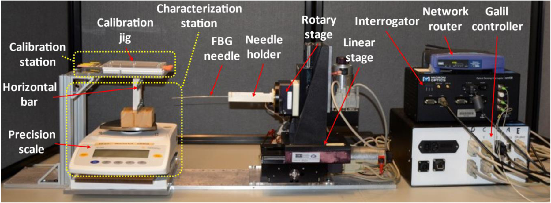
Robotic system assembly for FBG-sensorized needle calibration.
II. Materials & Methods
The FBG-sensorized needle to be used in this work is custom-made from purchased FBG fibers (Technica Optical Components, LLC., Atlanta, GA), 80 μm cladding diameter with three fiber channels and three active sensing locations (5 mm length) referred to as active areas (AA). The three channels are all inside the inner stylet of the needle as shown in Fig. 2 with the center of the active areas at 11, 26 and 70 mm from the tip of the needle. The inner stylet of the needle consists of a titanium wire with 635 μm diameter and 200 mm length. Three V-shape grooves, each with 90 degrees angle and 150 micrometers depth, were cut on the wire with a milling machine and a special jig that ensures the angle between the grooves are exactly 120 degrees. Outer sheath consists of a 18 gauge, 200 mm, MRI-compatible needle (Type KIM18/20, Innovative Tomography Products GmbH, Bochum, Germany) with its inner stylet replaced by the custom-built titanium wire. UV glue (AA 3922, Loctite, Henkel) was used to attach the FBG fibers to the titanium inner stylet. In addition, one of the fibers is carefully aligned with the bevel tip of the needle outer sheath. The FBG-sensorized needle is chosen for several reasons. FBG sensors transmits light of specific wavelength as data using glass fibers instead of electrical signals through metal wires, and is thus compatible to MRI-guided procedures [11]. It also has extremely high spatial resolutions as high as 10 microns, resulting in high accuracy in its measurements [13]. In addition, it also has real-time sensing capability, as it has up to 1kHz of acquisition frequency.
Fig. 2.
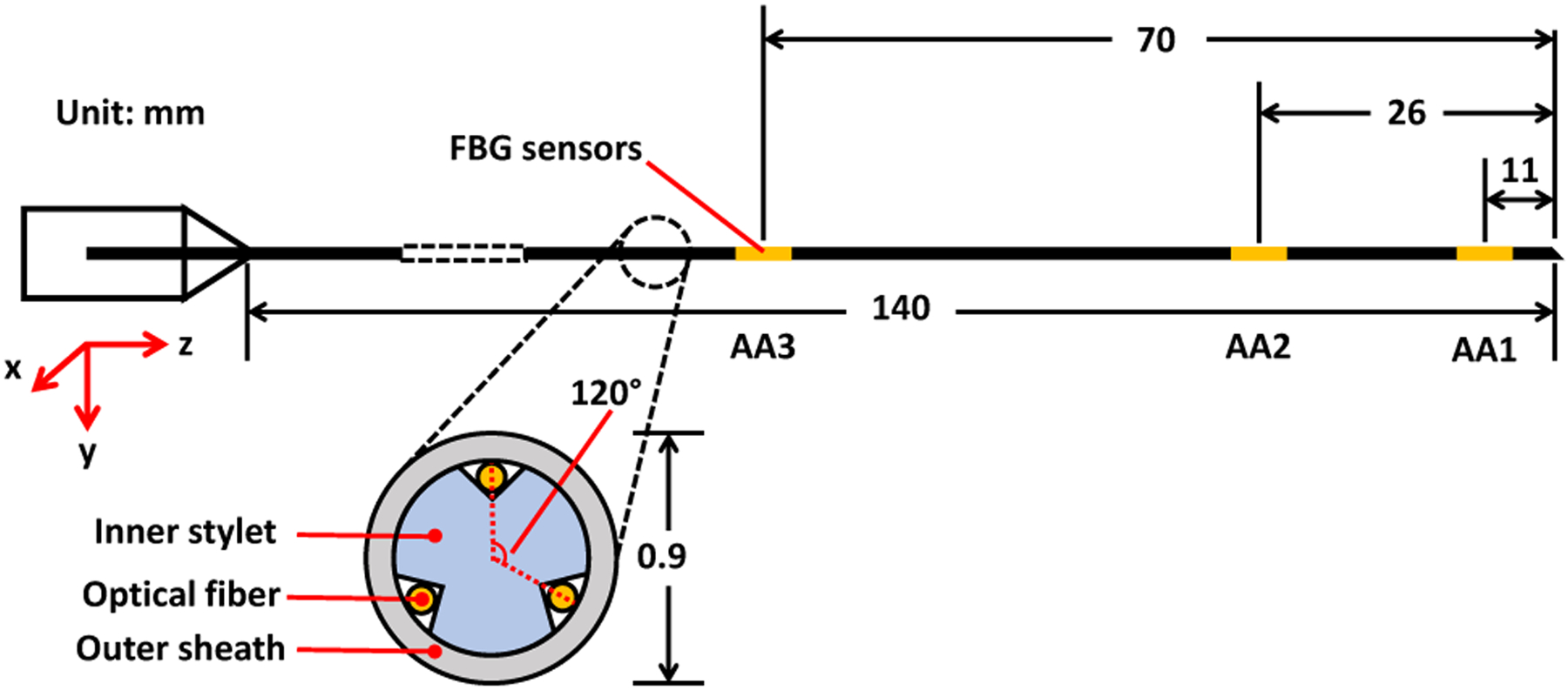
Design of an FBG-sensorized needle used for this study.
The main principle of using FBG sensors to reconstruct bending curvature is the FBG’s ability to sense strain. FBG fibers reflect light at a specific peak wavelength called the Bragg wavelength, depending on the strain and temperature that the fibers are experiencing. When assuming symmetry about the bending plane of each fiber with negligible twisting and buckling, the change in the FBG fiber’s Bragg wavelength ΔλB has the following relationship with the change of strain Δϵ that it experiences:
| (1) |
where is the fiber’s unstrained Bragg wavelength, Sϵ and ST are the strain and temperature sensitivity coefficients, and ΔT is the change in temperature of the sensor [13]. On the other hand, according to Euler-Bernoulli beam theory, the strain ϵ of a beam is related to its curvature κ through the equation:
| (2) |
where y is the distance from the neutral bending plane. Thus combining equations (1) and (2), a linear relationship can be observed between the change of the FBG fiber’s Bragg wavelength ΔλB and its change of curvature Δκ when the environmental temperature is constant:
| (3) |
Therefore, the FBG sensors can be calibrated by calculating the coefficient C through multiple ΔλB and Δκ values obtained experimentally. In terms of the 3-channel 3-AA FBG-sensorized needle that is used in this study, its calibration requires calculating a set of three 3 × 2 calibration matrices Ci,
| (4) |
For each element Cijab in Ci, i represents individual active areas, j represents each individual channel, and ab is the specific bending plane.The robotic calibration system must perform two processes sequentially. First, it needs to perform characterization process for the needle to be tested. This step aims to check if the needle has manufacturing problems like a twisted fiber inside the needle or any other issue that renders the previously mentioned assumptions inapplicable, and the needle will be rebuilt to resolve the problems that were indicated from the characterization process. After characterization, the sensorized needle will undergo a calibration process to obtain its calibration matrices that correlates the FBG wavelength shift per AA with the curvature of the needle. As shown in (3), there is a linear relationship between the FBG fiber’s change in Bragg wavelength and its change in curvature, and the calibration matrices are combinations of the linear coefficients for all fibers at each active area. The set of calibration matrices obtained is then verified by comparing the calculated needle curvature using the obtained calibration matrices to the actual needle curvature.
The current manual procedure setup is as follows. To perform the characterization of the needle, the needle tip is first fixed on a horizontal bar that is attached to a precision scale (Fig. 1). The needle location is then adjusted vertically so that the scale reading is zero while the needle tip is still touching the horizontal bar. This is to make sure that the bending distance of the needle is zero at the beginning of the test. Then the needle is pressed down on the scale in 10 repetitions of 1 mm increments. After each increment, 200 signals are collected from the needle. Then the needle is released upwards for 10 repetitions of 1mm increments, with the same number of signals collected after each increment. This is defined as one load-unload cycle, and this cycle is to be repeated for at least 5 times to conclude the data collection process. To fully validate the needle construction, such a characterization process needs to be performed for each FBG channel of the needle. As one of the fibers is aligned with the bevel tip of the needle, during the characterization of that fiber channel, the needle bevel tip is aligned carefully with the needle’s contact point to the horizontal bar. This is to ensure that the fiber to be tested is on the central vertical plane of the needle. For the characterization process of the other two fibers, the needle needs to be rotated 120 degrees towards the corresponding fiber so that the fiber to be tested is on the central vertical plane of the needle as well. Theoretically, during characterization of each FBG channel, the other two FBG fibers will be symmetrical about the needle’s central vertical plane, and will thus output very similar characterization results. Due to this reason, the similarity of the results produced by these fibers can also be used as a criterion in determining whether the needle was built as desired. To visualize the characterization results, the FBG wavelength shift is compared to linear fits between the tip displacement and the wavelength shift.
For the calibration process, the needle is inserted repeatedly into slots (18 gauge needles with OD 1.3 mm and ID 1.0 mm) with predetermined constant curvatures on a calibration jig (Fig. 3). This experimental setup will enable us to examine the effect of constant, discrete curvature along the needle in both positive and negative directions. The insertion process is repeated 10 times for each single slot, and with the needle rotated at 0, ±90, and 180 degrees along its axial direction. The calibration matrix for each active area of the needle can then be calculated through least-squares fit between the FBG data and the curvature data [14]. The obtained calibration matrices are then validated by repeating the calibration process on a different jig with different slots and using the matrices to estimate the curvatures.
Fig. 3.
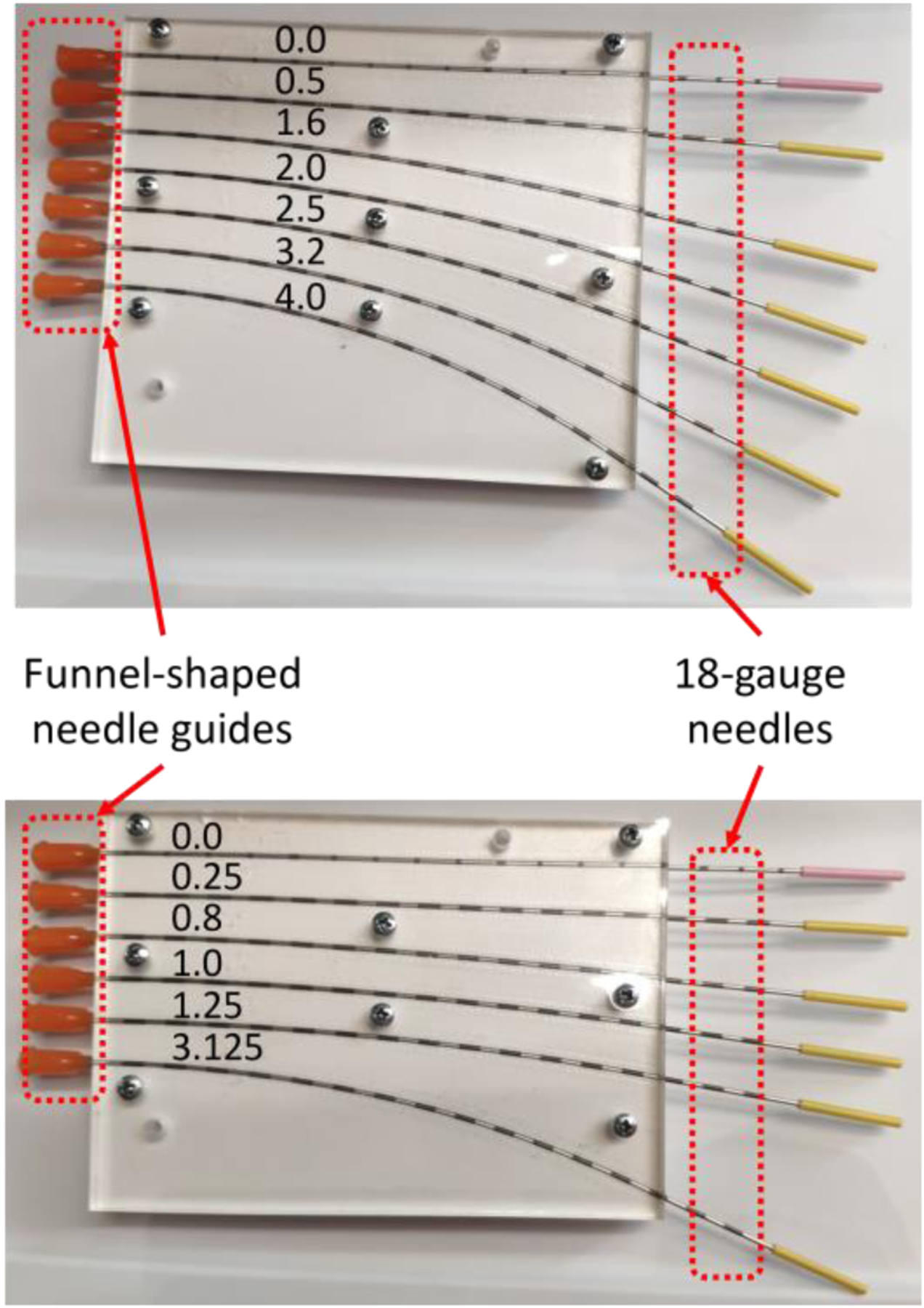
Calibration jig (top) and validation jig (bottom) with precurved slots with constant curvatures (unit: 1/m).
III. System Setup & Experiments
The robotic system was built to perform both characterization and calibration processes automatically. The setup of the system is shown in Fig. 1. The entire building process was divided into two components, the hardware component, which is the calibration platform, as well as the software component, which is the algorithm to control the movement of the robotic system and to collect data.
A. Calibration Platform
According to the current calibration procedure, two types of testing are needed to fully calibrate a needle, so a calibration platform was built to have the correct setup for both testing processes. Based on that, the calibration platform is divided into four sections: the robotic needle holder, the characterization station, the calibration station, and the data collection unit.
The robotic needle holder section consists of a 3-DOF (degree-of-freedom) linear stage (XYR-6060 & LM-400, Dover Motion, Boxborough, MA), a rotary stage (B5990TS, Velmex, Inc., Bloomfield, NY), and a 3D printed needle holder, and its purpose is to move the needle to the corresponding stations and perform the tests. At the characterization station, there is a precision scale (GC2502, Sartorius, Göttingen, Germany) with a custom-made piece glued to its weighing platform. The purpose of the piece is to provide a heightened horizontal bar with a point contact of which the needle tip can be fixed at. The calibration station, which is directly on top of the characterization station, consists of a 3D printed calibration jig with multiple slots of predetermined constant curvature (Fig. 3). The entire platform is supported by aluminum profiles and acrylic plates, as well as a base platform. The data collection units are independent from the platform, and consist of a Galil controller (DMC-2143, Galil Motion Control, Rocklin, CA) to control both the linear stage and the rotary stage, an interrogator (sm130, Micron Optics, Roanoke, VA) to receive data from the FBG needle, and a network router (WRT54G, Belkin International, Inc., Playa Vista, CA) to transmit data from the interrogator to the computer.
B. Algorithm
The algorithm for the system is written in MATLAB R2020b implemented on a Windows 10 system. The overall workflow of the algorithm is shown in Fig. 4. For the FBG-based needle shape calibration process, the goal is to develop a fully automatic system, and as a first step, the system that is presented in this paper is semi-automatic that may require occasional manual support.
Fig. 4.
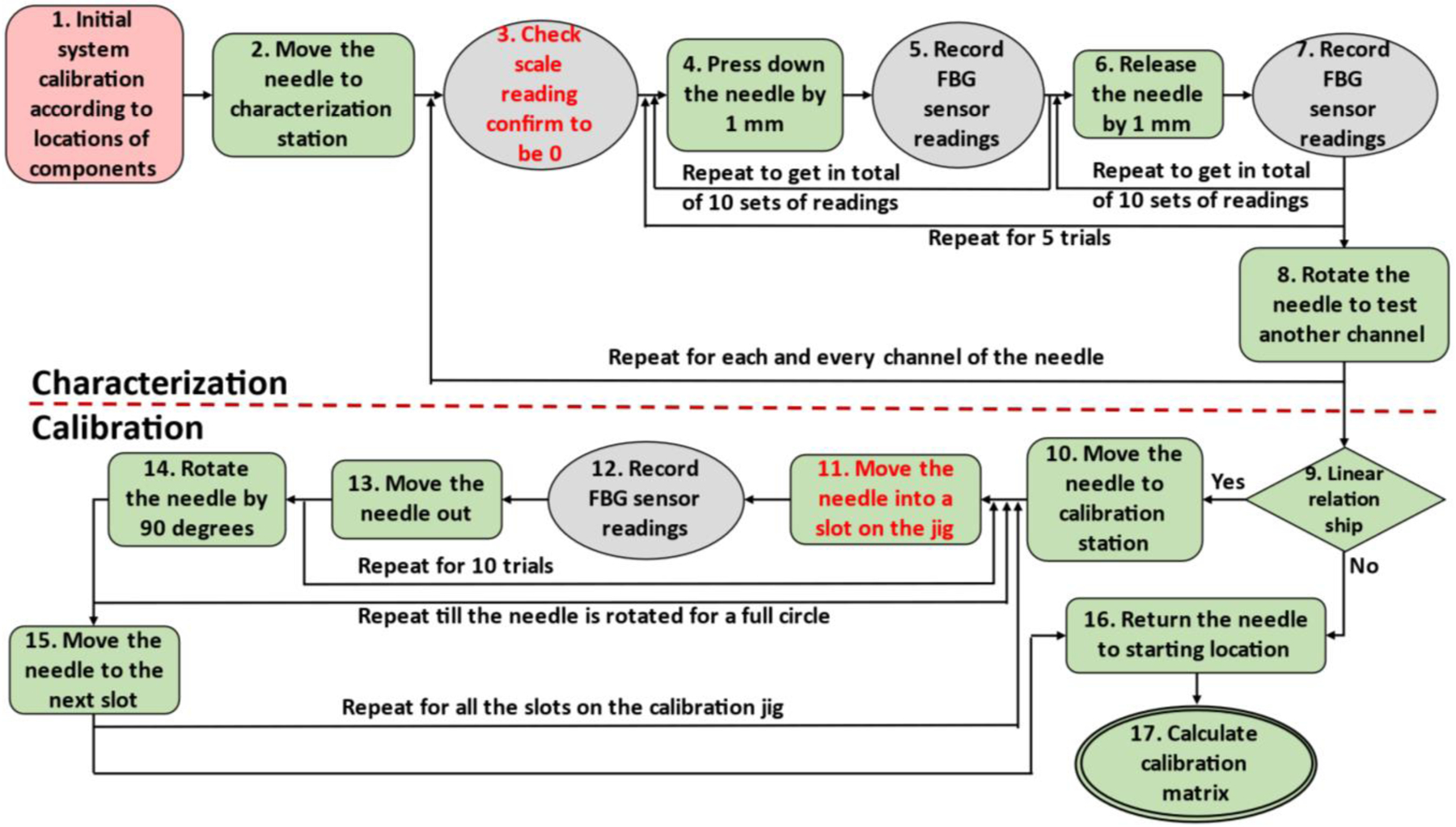
Workflow of the robotic calibration system. The red block is performed manually, the green blocks are performed automatically, the grey blocks are data collection steps and steps with red font requires manual assistance.
The two operations (#3 and #11, see Fig. 4) that need occasional manual interference are due to hardware limitations. The first operation (#3) is to confirm that the scale reading is zero. The manual portion of the operation is in calibrating the precision scale. As the scale was intended for static measurements, it will experience some measurement drift as the characterization process is conducted. On the other hand, as the needles are likely not perfectly straight, it is possible that the location with zero bending distance will shift as well. Thus, it is necessary to use the precision scale readings to reconfirm the zero-reading point every time after the needle is rotated, and it is also necessary to tare the scale every time beforehand. Currently this step is still performed manually, and is considered acceptable as it only involves taring the scale.
The other operation (#11) that needs manual interference is when inserting the needle into the slots on the calibration jig. This step has the smallest clearance in operation throughout the entire calibration process, because the slots are closely fitted to the needle, and a slight misalignment of the needle tip will result in insertion failure. Currently funnel-shaped guides are placed at the entry points of the calibration slots (Fig. 3) in order to assist guiding the needle during insertion process, but the effect of the guides is not ideal. Thus, for the current prototype, manual guidance is still required for the needle to be successfully inserted into each calibration slot, and the funnel-shaped guides are used during the insertion process to prevent the needle from being touched by the operator.
Since the needle tip will remain in the calibration slot during the repeated insertion and retraction steps, the timespan and frequency of manual intervention are significantly reduced in the calibration procedure. During the entire calibration process, there are only six instances where the needle needs manual guidance, which are the initial insertions to each calibration slot.
After all data collection steps, the data need to be processed to eliminate possible influences due to difference in different optic fibers as well as temperature fluctuation. All raw data are first shifted linearly so that the FBG readings are all zero when the needle is straight. Then for all data obtained for each curvature, the wavelength shift of all channels at each active area are averaged and subtracted from all the shifted data, thus eliminating the ambient errors that affects all the optical fibers at the same time, including temperature fluctuation. The processed data is correlated only to the strain of the FBG sensor. The data is then used to calculate the set of calibration matrices of the needle, which is temperature independent as well.
IV. Results & Discussion
After the system was built, one set of needle calibration process was conducted on an FBG-sensorized needle, and the results are reported.
The entire needle calibration process took in total 2 hours and 50 minutes, with the characterization process taking 20 minutes and the calibration process taking 2 hours and 30 minutes. The validation process took an additional 2 hours and 15 minutes. This total time span is shorter than the manual process in each step, which usually takes 30 minutes for needle characterization, about 3 hours for needle calibration and about 2 hours and 30 minutes for validation. At the same time, the time that needed human interaction was greatly reduced. For manual process, almost the entire calibration and validation procedures require manual operation, whereas during the robotic process, manual operation is only required for three times of scale taring and six times of needle insertion guidance, which takes less than 1 minute for each operation and less than 10 minutes overall. Thus, this robotic calibration system does not require any human attention for the majority of the testing process, saving a lot of operator attention time during the calibration process.
After the data were collected both automatically and manually, they were first checked for normal distribution, and the sample plots are shown in Fig. 5. It is clear that data collected during each trial of the experiments are all roughly normally distributed, proving that the data collection process was not subject to biases. For the characterization step, both manual and automatic processes produced nearly identical results, as seen in Fig. 6. The linear fit model for FBG data at each active area are very similar, and all models fit the data with R2 values greater than 0.99, meaning that the obtained FBG wavelength shift data are all proportional to the tip deflection distance. This is expected, as the characterization step only reflects the needle’s change of wavelength with respect to its bending distance, and thus should not be affected by how the needle characterization is performed.
Fig. 5.
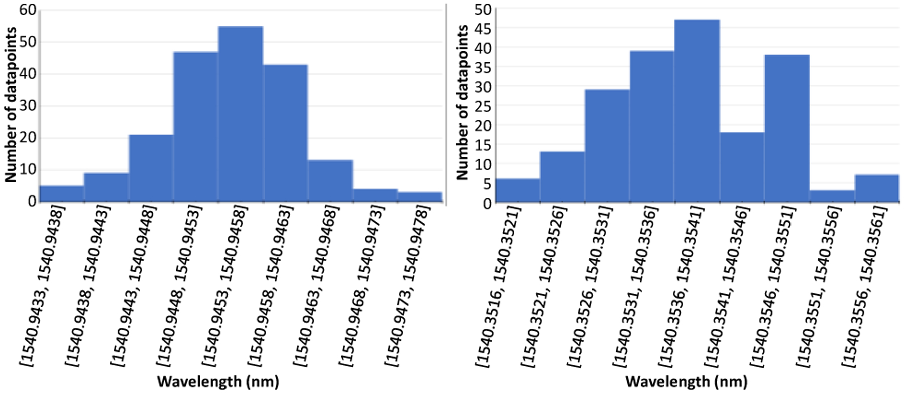
Sample histogram of 200 FBG wavelengths collected for manual(left) and automatic(right) calibrations.
Fig. 6.
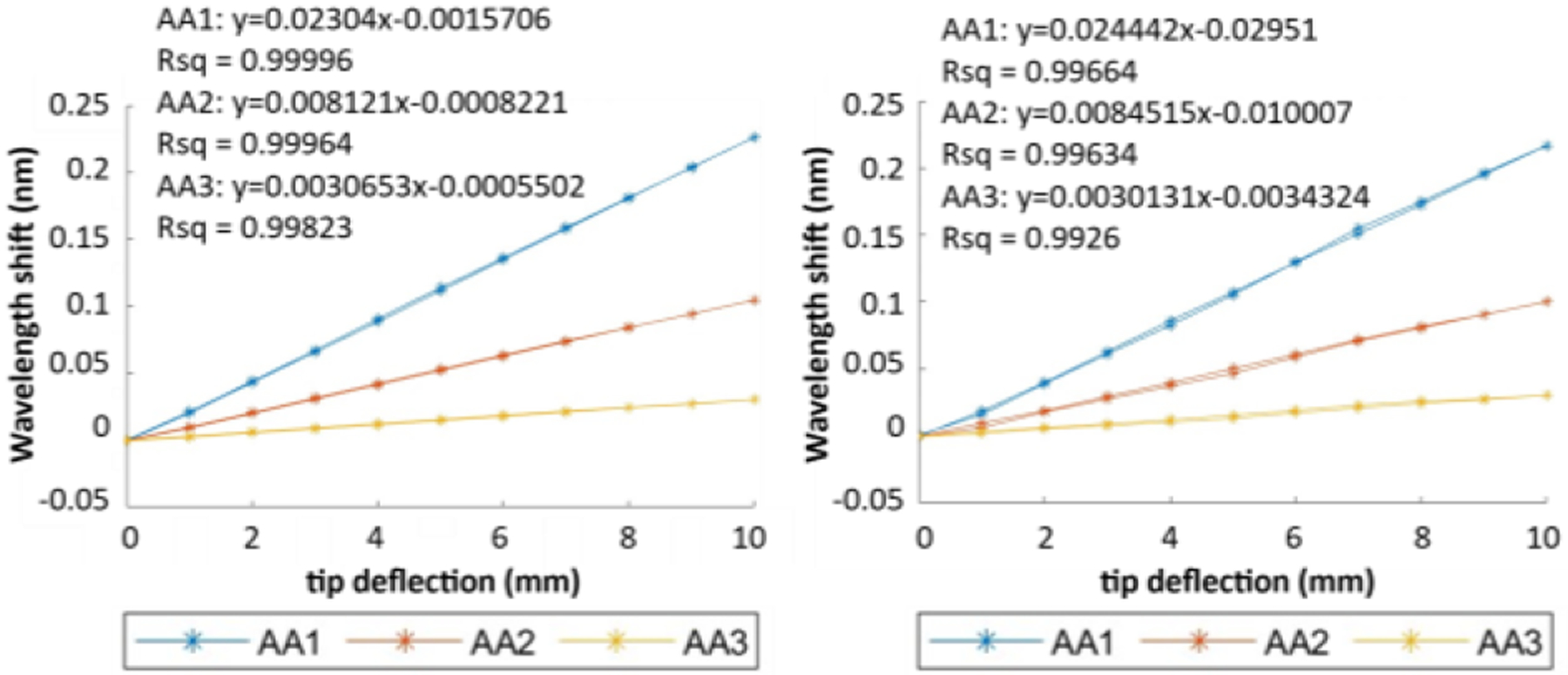
Sample characterization result of an FBG needle using manual (left) and robotic (right) calibrations.
The output of the calibration process is a set of calibration matrices for the needle, and the set of matrices obtained from manual and robotic calibrations of the same needle are shown in (5) and (6) respectively.
| (5) |
| (6) |
The two set of matrices are similar but some distinct discrepancies are still present, especially between the matrix C1 from manual and robotic calibrations. Thus, validation process is necessary to calculate the accuracy of the calibration matrices obtained.
Validation step is done by inserting the needle into another constant curvature jig with different curvature values as shown in Fig. 3 and using the FBG data to estimate the curvature values of the calibration slots. A sample plot of the wavelength shift of FBG sensor with respect to the curvature is shown in Fig. 7. Wavelength shift data from most of the channels can be fitted well with linear models (R2 > 0.97), meaning that the relationship between the wavelength shift and the curvature is roughly linear, which is consistent with (3). The only exception to this observation is for the wavelength shift data of channel 1 at yz-plane, of which the R2 value is only about 0.4. This is also reasonable as well, as its linear fit model is almost constant at y = 0, meaning that the wavelength shift of that FBG channel does not depend on the curvature at yz-plane at all. This conclusion is also supported by the mean μ and variance σ2 of this data series as well (μ = −0.019, σ2 = 8.33 × 10⁻⁴ for manual calibration and μ = −0.013, σ2 = 5.38 × 10⁻⁴ for robotic calibration).
Fig. 7.
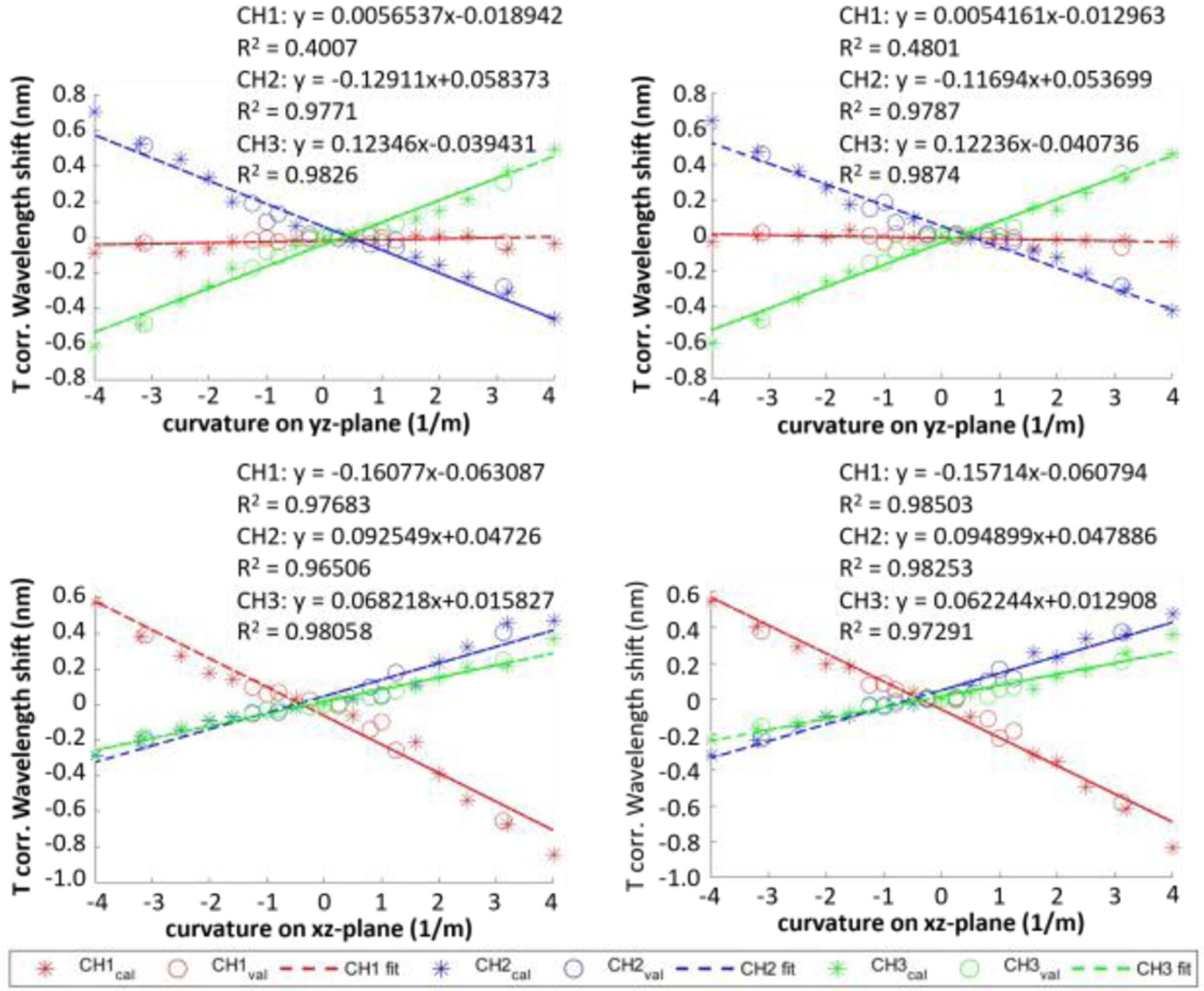
Temperature corrected wavelength shift of an FBG-sensorized needle with respect to curvatures of the needle along yz-plane (top) and xz-plane (bottom) obtained from manual (left) and robotic (right) calibrations.
The needle shape sensing model is used with the calibration matrices as well as a discrete model of the needle proposed in a previous research [14], and the validation error is calculated as the RMS distance error of all discrete needle locations between the reconstructed model and actual needle locations. The calibration process is considered successful if the validation error is less than 0.5mm. The validation errors of both automatic and manual data collection process are shown in Fig. 8. Based on the figure, the validation errors of both processes share the same trend, and for most curvatures both processes are able to produce successful calibration results. The one curvature value where the RMS errors exceed the threshold is considered outlier, which is not of concern as this large curvature value (3.125 1/m) is outside of clinically relevant needle shapes. The possible reason for these outliers is the play between the sensorized needle and the needle slots on the jigs. With bigger curvature, the needle tends to deviate more from the center of the needle slot, causing bigger errors. A two-sample t-test with equal variance was performed on the validation errors, and the result shows that the validation errors of the automatic and manual calibration process do not have significant difference (p-value = 0.405) and are thus very similar in terms of their accuracy. However, since the manual operator has been through the learning curve of performing manual needle calibration and has become very proficient in doing it, having a robotic system that performs as accurate as the manual calibration process is very beneficial as the operator does not have to go through the learning curve before producing such accurate results.
Fig. 8.
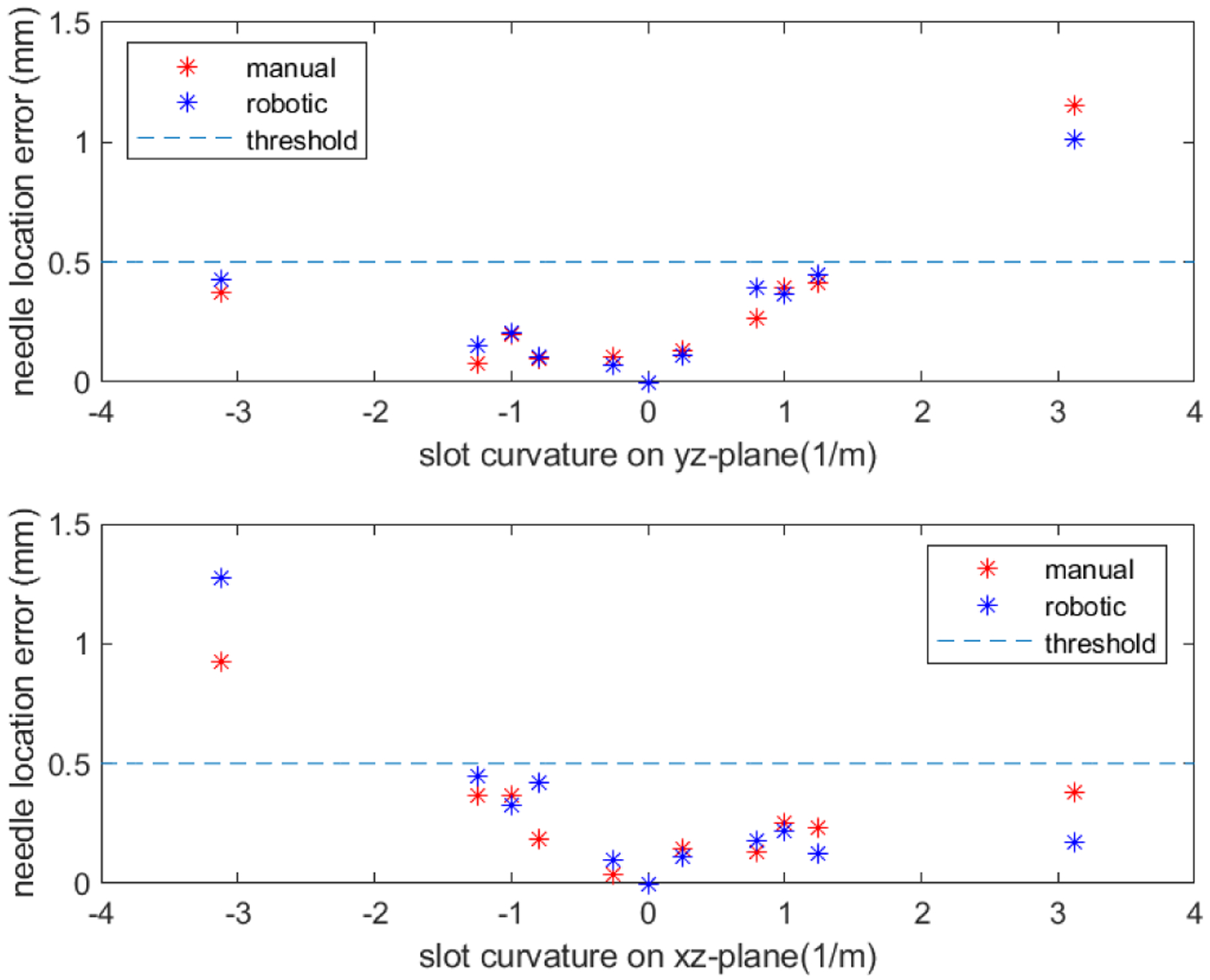
Needle location error of manual and robotic calibrations for curvatures along yz-plane (top) and xz-plane (bottom).
Errors are still present in the system. For example, there are occasionally some slight shaking of the system when the linear stage initiates movement, and the guiding slot on the calibration jig has a little bit of local bending near the entrance side. The effect of these imperfections of the system on the calibration result still needs to be studied, and can be researched further in the future. Also, more repetitions of the experiment could be done to ensure that the results are consistent enough to be applied. While the robotic calibration procedure aims to mitigate human errors, the manual-supported steps may still cause some errors during the experiment. Thus, it is important to improve the system to be fully automatic to avoid human errors as much as possible. This could be done by researching deeper into communication between MATLAB and the precision scale to fulfill automatic scale taring, as well as better design for funnel-shaped needle guidance for the calibration slots to enable automatic needle insertion. On the other hand, since the scale taring step of the algorithm is necessary only because the precision scale used in this study experiences measurement drifts during the characterization procedure, exploration and implementation of an alternative force measuring mechanism with similar accuracy to that of the precision scale but without measurement drifts can also be a solution towards a fully automatic calibration system. In addition, more experiments could be performed, including performing more trials on the same needle for better statistical power, as well as using a validation jig whose slots have varying curvatures for better simulation of its real-life applications.
V. Conclusion
This study explores the potential advantages of using a robotic system to perform FBG needle calibration, and demonstrates a robotic calibration system’s ability to produce comparable calibration accuracy as manual calibration performed by an experienced operator. The robotic system is also more time-efficient in performing the calibrations. Thus, time and human effort are saved in both training for expertise in calibration as well as the actual calibration procedure. With further improvement in force sensing at the needle tip as well as better needle guidance into the calibration slots, the system will be able to perform FBG needle calibration fully automatically, requiring even less time and human effort. Such a robotic calibration system can serve as a solid foundation for further research that need calibrated FBG-sensorized needles and can even be used as a standard for FBG needle calibration and validation.
Supplementary Material
Acknowledgments
This work has been supported by the National Institutes of Health under grant no. R01CA235134 and by Johns Hopkins University internal funds.
References
- [1].Siegel RL et al. , “Colorectal cancer statistics, 2020,” CA. Cancer J. Clin, vol. 70, no. 3, pp. 145–164, May 2020, doi: 10.3322/caac.21601. [DOI] [PubMed] [Google Scholar]
- [2].Loeb S, Carter HB, Berndt SI, Ricker W, and Schaeffer EM, “Complications After Prostate Biopsy: Data From SEER-Medicare,” J. Urol, vol. 186, no. 5, pp. 1830–1834, Nov. 2011, doi: 10.1016/j.juro.2011.06.057. [DOI] [PMC free article] [PubMed] [Google Scholar]
- [3].Seifabadi R, Iordachita I, and Fichtinger G, “Design of a teleoperated needle steering system for MRI-guided prostate interventions,” in 2012 4th IEEE RAS & EMBS International Conference on Biomedical Robotics and Biomechatronics (BioRob), Jun. 2012, pp. 793–798, doi: 10.1109/BioRob.2012.6290862. [DOI] [PMC free article] [PubMed] [Google Scholar]
- [4].Nath S, Chen Z, Yue N, Trumpore S, and Peschel R, “Dosimetric effects of needle divergence in prostate seed implant using 125I and 103Pd radioactive seeds,” Med. Phys, vol. 27, no. 5, pp. 1058–1066, May 2000, doi: 10.1118/1.598971. [DOI] [PubMed] [Google Scholar]
- [5].Wan G, Wei Z, Gardi L, Downey DB, and Fenster A, “Brachytherapy needle deflection evaluation and correction,” Med. Phys, vol. 32, no. 4, pp. 902–909, Mar. 2005, doi: 10.1118/1.1871372. [DOI] [PubMed] [Google Scholar]
- [6].Roberson PL, Narayana V, McShan DL, Winfield RJ, and McLaughlin PW, “Source placement error for permanent implant of the prostate,” Med. Phys, vol. 24, no. 2, pp. 251–257, Feb. 1997, doi: 10.1118/1.598058. [DOI] [PubMed] [Google Scholar]
- [7].Pouliot J, Taschereau R, Coté C, Roy J, and Tremblay D, “Dosimetric aspects of permanent radioactive implants for the treatment of prostate cancer,” Phys. Canada, vol. 55, no. 2, pp. 61–68, 1999. [Google Scholar]
- [8].Lezcano DA, Iordachita II, and Kim JS, “Trajectory Generation of FBG-Sensorized Needles for Insertions into Multi-Layer Tissue,” in 2020 IEEE SENSORS, Oct. 2020, pp. 1–4, doi: 10.1109/SENSORS47125.2020.9278807. [DOI] [PMC free article] [PubMed] [Google Scholar]
- [9].Kim JS, Chatrasingh M, Kim S, Suthakorn J, and Iordachita II, “Fiber Bragg Grating based needle shape sensing for needle steering system: Evaluation in inhomogeneous tissue,” in 2017 IEEE SENSORS, Oct. 2017, pp. 1–3, doi: 10.1109/ICSENS.2017.8234074.29780437 [DOI] [Google Scholar]
- [10].Roesthuis RJ, Janssen S, and Misra S, “On using an array of fiber Bragg grating sensors for closed-loop control of flexible minimally invasive surgical instruments,” in 2013 IEEE/RSJ International Conference on Intelligent Robots and Systems, Nov. 2013, pp. 2545–2551, doi: 10.1109/IROS.2013.6696715. [DOI] [Google Scholar]
- [11].Henken KR, Dankelman J, Van Den Dobbelsteen JJ, Cheng LK, and Van Der Heiden MS, “Error Analysis of FBG-Based Shape Sensors for Medical Needle Tracking,” IEEE/ASME Trans. Mechatronics, vol. 19, no. 5, pp. 1523–1531, Oct. 2014, doi: 10.1109/TMECH.2013.2287764. [DOI] [Google Scholar]
- [12].Park Y-L et al. , “Real-Time Estimation of 3-D Needle Shape and Deflection for MRI-Guided Interventions,” IEEE/ASME Trans. Mechatronics, vol. 15, no. 6, pp. 906–915, Dec. 2010, doi: 10.1109/TMECH.2010.2080360. [DOI] [PMC free article] [PubMed] [Google Scholar]
- [13].Al-Ahmad O, Ourak M, Van Roosbroeck J, Vlekken J, and Vander Poorten EB, “Improved FBG-Based Shape Sensing Methods for Vascular Catheterization Treatment,” IEEE Robot. Autom. Lett, vol. 5, no. 3, pp. 1–1, 2020, doi: 10.1109/LRA.2020.3003291. [DOI] [Google Scholar]
- [14].Kim JS, Guo J, Chatrasingh M, Kim S, and Iordachita I, “Shape determination during needle insertion With curvature measurements,” in 2017 IEEE/RSJ International Conference on Intelligent Robots and Systems (IROS), Sep. 2017, pp. 201–208, doi: 10.1109/IROS.2017.8202158. [DOI] [Google Scholar]
Associated Data
This section collects any data citations, data availability statements, or supplementary materials included in this article.


