

Abstract
Objective:
Cone-beam computed tomography (CBCT) is a reliable method of assessing the oral cavity and upper airways. We conducted this study to examine the changes introduced by rapid maxillary expansion in the nasal cavity, nasopharynx, and oropharynx as seen with images obtained by CBCT.
Materials and Methods:
We evaluated 15 patients with maxillary width deficiency treated with RME. Patients were subjected to CBCT at the beginning of RME and after the retention period of 4 months.
Results:
The nasal cavity presented a significant transverse increase in the lower third, in the anterior (1.08 mm ± 0.15), medium (1.28 mm ± 0.15), and posterior regions (0.77 mm ± 0.12). No significant change occurred in the nasopharynx in volume (P = .11), median sagittal area (P = .33), or lower axial area (P = .29) resulting from the RME. A significant change was noted in the oropharynx in volume (P = .05), median sagittal area (P = .01), and lower axial area (P = .04) before and immediately after the RME.
Conclusions:
RME is able to increase the transverse width of the nasal cavity, but it does not have the same effect in the nasopharynx. Changes noted in the oropharynx may be due to the lack of a standardized position of the head and tongue at the time of image acquisition.
Keywords: Rapid maxillary expansion, Cone-beam computed tomographic, Upper airway
INTRODUCTION
Transverse deficiency of the maxilla is related to insufficient development of the maxillary width, usually showing a clinical posterior crossbite.1 To restore the dimensions of the maxillary arch, rapid maxillary expansion (RME) is often used. It consists of a routine orthodontic clinical procedure in which orthopedic force is applied to promote opening of the median palatal suture.2 Owing to the anatomic proximity of the upper airway and the maxilla, the effects of this procedure on breathing have been studied extensively in the literature, and several imaging methods have been proposed and used. Recently, cone-beam computed tomography (CBCT) was introduced in dentistry and has been widely used because this image method allows the use of software reconstruction in three dimensions, which enables the manipulation of images in three space planes and considerably reduces the absorbed radiation.3–5
CBCT has been used to evaluate the effects of RME in the airways. Results have shown good repeatability (intraexaminer) and good reproducibility (interexaminer), therefore making it a reliable method to use in evaluating images in the upper airway region.6
Even though CBCT is considered the best method for evaluating the upper airway, studies from different centers have shown conflicting results. Some authors claim that there is no evidence to support the hypothesis that no change of volume occurs in the region of the nasal cavity and oropharynx after RME.7–9 Conversely, other authors believe that RME increases the nasal volume and therefore could increase nasal permeability and establish a pattern of nose breathing.8
Because cone-beam computed tomography is considered a reliable method of assessing the oral cavity and upper airways, we conducted this study to examine possible changes in the upper airway after RME.
MATERIALS AND METHODS
This study was approved by the Ethics Committee of the Dentistry School at the University of São Paulo under protocol 170/2010. The sample was composed of 15 pairs of tomographic images acquired by three-dimensional volumetric CBCT corresponding to 15 mixed dentition individuals (8 females and 7 males). These patients had a transverse maxillary deficiency and a unilateral posterior crossbite, and they had an average age of 7.5 years at the beginning of treatment. All patients were treated with rapid maxillary expansion using a fixed appliance with occlusal acrylic coating, as illustrated in Figure 1. Patients were evaluated before (M1) and 4 months after the RME (M2). The equipment used for CBCT was the i-Cat® (Cone beam 3-D Dental Imaging System, Imaging Sciences International, Hatfield, Pa), and images were analyzed using Dolphin 3D® software (Dolphin Imaging/Patterson Dental, Chatsworth, Calif). To perform nasal cavity evaluation in Dolphin 3D®, images were positioned such that the axial plane passed through the palatal plane (ANS-PNS) in view of the median sagittal plane, and the LA point was located. From this point, two other points were located every 15 mm, representing the medial and posterior regions of the nasal cavity (Figure 2). Anterior, medial, and posterior areas were evaluated transversally in the lower third of the coronal slice (Figure 3).
Figure 1.
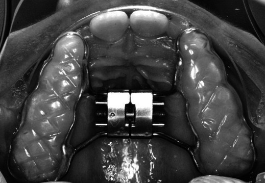
Dento-supported device.
Figure 2.

(A) Axial positioning of the palatal plane and determination of the point VA. (B) Determination of the anterior, middle, and posterior nasal cavity.
Figure 3.

(A) Upper and lower limits of the anterior portion of the nasal cavity divided into thirds and lateral distance in the lower third. (B) Upper and lower limits of the middle portion of the nasal cavity divided into thirds and lateral distance in the lower third. (C) Upper and lower limits of the posterior nasal cavity divided into thirds and lateral distance in the lower third.
Craniocervical positioning between the two phases evaluated was verified with the angular measurements SN.C2s-C2i and SN.C2s-C4I, and the linear distance between the C4I and Me points verified the sagittal positioning of the mandible (Figures 4 and 5).
Figure 4.

Cephalometric points marked for evaluation of craniocervical positioning and placement of the sagittal jaw.
Figure 5.

(A) SN.C2s-C2i angle. (B) SN.C2s-C4i angle. (C) Distance between the points and C4I Me.
In the evaluation of the nasal and oropharyngeal space, images were standardized according to the orientation of the position of the skull as described by Palomino-Gómez,6 such that the images would be positioned the same way at both time points. For evaluation of the nasopharynx, points were located in the posterior nasal spine (PNS), vomer posterior (VP), horizontal extension point VP and vertical extension point ENP (VA), basion (Ba), PPINf (located 15 mm posterior to the lower limit of the uvula), and PAINf (located 15 mm above the lower limit to the uvula) (Figure 6A). After determination of the sensitivity, measurements of volume, smaller axial area, and sagittal area for this region were generated. For evaluation of the oropharynx, the upper limit of the epiglottis was identified in the coronal plane, cut as this is in its greatest length, and its uppermost portion was landmarked. With the image in sagittal, this region was delimited by joining PPINf' and the PAINf', and points were created at PAIOf' and PPIOf located 15 mm anterior and posterior, respectively, from the point of the uvula. This definition should extend beyond the limits of the upper airways in all planes (sagittal, coronal, and axial). Sensitivity was determined using the same criteria as were used for evaluation of the nasopharynx (Figure 6B).
Figure 6.

(A) Nasopharynx and (B) oropharynx delimitation.
To analyze the variables between M1 and M2, a Student's t-test was used after the Kolmogorv-Smirnov test was applied at the significance level of 5%. To evaluate the correlation between variables of the oropharynx and cranial-cervical inclination and mandibular positioning, Pearson's linear correlation coefficient was applied.
RESULTS
Measures of SN.C2s C2i, SN.C2s-C4I, and the C3i-Me line at moments 1 and 2 showed no statistically significant difference with respect to the craniocervical inclination and mandibular positioning (Table 1).
Table 1.
Mean, Standard Deviation, Standard Error, and Results of Student's t-Test for the Angles and SN.C2s C2i, SN.C2s-C4I-line, and C3i Mea

Measurements of nasal cavity variables in each observation period showed a significant median increase in all variables after the RME (Table 2). In measurements of the nasopharynx, a median increase in volume and a smaller axial area were not statistically significant. For the sagittal area, no statistical difference between times of evaluation was noted (Table 3). A significant increase was seen in the oropharynx region after the procedure (Table 3). Results of Pearson's correlation between the variables of craniocervical inclination, sagittal positioning of the mandible, and oropharynx variables showed no positive correlations (Table 4 and 5).
Table 2.
Mean, Standard Deviation, and Results of Student's t-Test (5% Significance) for the Variables of the Nasal Cavity Between M1 and M2

Table 3.
Mean, Standard Deviation, and Results of Student's t-Test (5% Significance) for the Variables of the Nasopharynx Between M1 and M2

Table 4.
Mean, Standard Deviation, and Results of Student's t-Test (5% Significance) for the Variables of the Oropharynx Between M1 and M2

Table 5.
Pearson Linear Correlation With the Oropharynx in the Studied Sample

DISCUSSION
The benefits of RME on the dimensions of the jaws, nose, and other facial structures have been studied by orthodontists and otorhinolaryngologists.9–14 Lack of details and superposition of images are the limitations associated with using conventional radiographs to determine the precise anatomic limits of the nasal cavity.15 Moreover, the accuracy and quality of images obtained by cone-beam computed tomography have led the authors of recent research involving upper airway structures5,15,16 to choose it as the preferred method.
When the midpalatal suture is subjected to expansion forces, it separates in a nonparallel fashion. Because the maxilla articulates with bones that are not paired, the amount of separation is limited.17 Silva Filho et al.18 found that the palatal suture does not follow a parallel opening configuration in the axial plane, with its greatest width toward the anterior area. However, results of this current study show that the observed expansion pattern on the nasal cavity floor does not maintain this pattern of opening. We found the largest significant increase in the transverse middle region of the nasal cavity (1.28 mm) compared with the anterior (1.08 mm) and posterior regions (0.77 mm) when evaluated on the nasal floor in the coronal plane.
On the other hand, Palaisa et al.10 observed that the increase in transversal areas of the anterior, middle, and posterior nasal cavity was larger than in the middle (8.77 cm2) and posterior areas (9.13 cm2) in relation to the anterior area (7.31 cm2) nasal cavity. Thus, they found that RME in the nasal cavity could not be performed with maintenance of the standard triangular opening of the sutures.
Several methods have been proposed to evaluate the airway in studies with CBCT. Some of these studies are based on parameters used in conventional radiography.19,20 Many studies20,21 chose the beginning of the airway in the height of the PNS (posterior nasal spine point); however, other studies performed measurements from the region corresponding to the pharyngeal tonsil.6,9 In this study, the first reference point of nasopharynx delimitation was located in the choana, including the area of the pharyngeal tonsil, and continued to the inferior portion of the soft palate. It is very important to include this structure in the measurements because hypertrophy of lymphoid tissue is one of the most common causes of nasal obstruction. In our sample, we observed that there was a mean increase in the absolute numbers of the nasopharynx volume, but this change was not statistically significant (P = .11).
Zhao et al.,7 who analyzed the same area with CBCT before and 15 months after RME, found no significant differences in the volume of the oropharynx and nasopharynx. They reported that the hypothesis that there is a change in the upper airways after the procedure is not supported. Results of the present study were similar to other findings19,22 in which no significant changes in the dimensions of the nasopharynx after RME were observed. Usumez et al.22 evaluated lateral cephalograms of 8 patients after 8 months of the RME procedure and observed increases in the absolute mean values in this region, but they attributed the lack of statistical significance of this variable to the small sample size. Charoenworaluck19 evaluated the effects of RME on the nasopharynx after 1 year of the active phase of treatment and noted an increase in the airway. However, this increase is not statistically significant, and it is possible that growth changed the immediate effects of maxillary expansion.
Few studies have evaluated the effects of maxillary expansion in the oropharynx, and none of them found significant changes in the dimensions of this region after maxillary expansion.19,23 In this study, we observed a significant increase in this region in all variables (Table 4). It is important to mention that several studies in the literature correlate head posture with dimension changes of the upper airways, especially in the oropharynx.23 Ingman et al.24 suggested that the change in the oropharynx may be associated with the change in head position. However, the present study showed no statistically significant correlation between the craniocervical inclination as measured by the angle C2i SN.C2s-SN-C2s-C41, volume change, and the axial area of the oropharynx. However, it needs to be emphasized that there was a strong variation in the craniocervical inclination of patients between M1 and M2, as shown by the increased standard deviation (Table 1). Other factors that could influence the dimensions of the oropharynx are tongue position at the time of acquisition of the examination and repositioning of the tongue and the mandible due to the clinical procedure (ie, after RME and anterior mandibular repositioning as a direct consequence of the jaw expansion). However, the lack of control over tongue positioning and adjacent soft tissues associated with breathing movements and swallowing can be a limiting factor in the evaluation of the oropharynx in CBCT examinations, leading to errors in interpreting the data, such as the shape and volume of this region.
CONCLUSIONS
RME produces a significant transversal increase in the lower third of the nasal cavity 4 months after the procedure.
There was no significant change in volume, sagittal median area, or axial minimal area in the nasopharynx as a result of the RME.
A significant change in the oropharynx was noted after the RME; however, this change may reflect inconsistencies in the examination acquisition because tongue posture, head inclination, and breathing and swallowing movements were not standardized between patients.
REFERENCES
- 1.Sant'Ana L. F. M, Gurgel J. A. Proposta de método para controle dos resultados da expansão rápida da maxila assistida cirurgicamente. OrtodontiaSPO. 2006;39:244–250. [Google Scholar]
- 2.Garib D. G, Henriques J. F. C, Carvalho P. E. G, Gomes S. C. Longitudinal effects of rapid maxillary expansion: a retrospective cephalometric study. Angle Orthod. 2007;77:442–448. doi: 10.2319/0003-3219(2007)077[0442:LEORME]2.0.CO;2. [DOI] [PubMed] [Google Scholar]
- 3.Lima Filho R. M. A, Lima A. C, Ruellas A. C. O. Spontaneous correction of Class II malocclusion after rapid palatal expansion. Angle Orthod. 2003;73:745–752. doi: 10.1043/0003-3219(2003)073<0745:SCOCIM>2.0.CO;2. [DOI] [PubMed] [Google Scholar]
- 4.Holberg C, Steinhäuser S, Geis P, Rudzki-Janson I. Cone-beam computed tomography in orthodontics: benefits and limitations. Am J Orthod Dentofac Orthop. 2005;66:434–444. doi: 10.1007/s00056-005-0519-z. [DOI] [PubMed] [Google Scholar]
- 5.Mozzo P, Procacci C, Tacconi A, Martini P. T, Andreis I. A. A new volumetric machine for dental imaging based on the cone-beam technique: preliminary results. Eur Radiol. 1998;8:1558–1564. doi: 10.1007/s003300050586. [DOI] [PubMed] [Google Scholar]
- 6.Palomino-Gómez S. P. Cone Beam Computed Tomography to Evaluate the Effect of the Herbst Appliance in Pharyngeal Airway Space in Patients Class II Division 1 [master's thesis] Araraquara, Brazil: Universidade Estadual Paulista “Julio de Mesquita Filho”; 2010. [Google Scholar]
- 7.Zhao Y, Nguyen M, Gohl E, Mah J. K, Sameshima G, Encisof R. Oropharyngeal airway changes after rapid palatal expansion evaluated with cone-beam computed tomography. Am J Orthod Dentofac Orthop. 2010;137(4 suppl 1):S71–S78. doi: 10.1016/j.ajodo.2008.08.026. [DOI] [PubMed] [Google Scholar]
- 8.Haralambidis A, Ari-Demirkaya A, Acar A, Küçükkeleş N, Ateş M, Ozkaya S. Morphologic changes of the nasal cavity induced by rapid maxillary expansion: a study on 3-dimensional computed tomography model. Am J Orthod Dentofacial Orthop. 2009;136:815–818. doi: 10.1016/j.ajodo.2008.03.020. [DOI] [PubMed] [Google Scholar]
- 9.Garib D. G, Henriques J. F, Janson G, Freitas M. R, Coelho R. A. Rapid maxillary expansion—tooth tissue-borne versus toothborne expanders: a computed tomography evaluation of dentoskeletal effects. Angle Orthod. 2005;75:548–557. doi: 10.1043/0003-3219(2005)75[548:RMETVT]2.0.CO;2. [DOI] [PubMed] [Google Scholar]
- 10.Palaisa J, Ngan P, Martin C, Razmus T. Use of conventional tomography to evaluate changes in the nasal cavity with rapid palatal expansion. Am J Orthod Dentofacial Orthop. 2007;132:458–466. doi: 10.1016/j.ajodo.2005.10.025. [DOI] [PubMed] [Google Scholar]
- 11.Garret B. J, Caruso J. M, Rungcharassaeng K, Farrage J. R, Kim J. S, Taylor G. D. Skeletal effects to the maxilla after rapid maxillary expansion assessed with cone-beam computed tomography. Am J Orthod Dentofacial Orthop. 2008;134:8.e1–e11. doi: 10.1016/j.ajodo.2008.06.004. [DOI] [PubMed] [Google Scholar]
- 12.De Felippe N. L. O, Da Silveira A. C, Viana G, Kusnoto B, Smith B, Evans C. A. Relationship between rapid maxillary expansion and nasal cavity size and airway resistance: short and long tRME effects. Am J Orthod Dentofacial Orthop. 2008;134:370–382. doi: 10.1016/j.ajodo.2006.10.034. [DOI] [PubMed] [Google Scholar]
- 13.Gohl E, Nguyen M, Enciso R. Three-dimensional computed tomography comparison of the maxillary palatal vault between patients with rapid palatal expansion and orthodontically treated controls. Am J Orthod Dentofac Orthop. 2010;138:477–485. doi: 10.1016/j.ajodo.2008.12.025. [DOI] [PubMed] [Google Scholar]
- 14.Langer M. R. E, Itikawa C. E, Valera F. C. P, Matsumoto M. A. N, Anselmo-Lima W. T. Does rapid maxillary expansion increase nasopharyngeal space and improve nasal airway resistance? Int J Pediatr Otorhinolaringol. 2011;75:122–125. doi: 10.1016/j.ijporl.2010.10.023. [DOI] [PubMed] [Google Scholar]
- 15.Hatcher D. C, Aboudara C. L. Diagnosis goes digital. Am J Orthod Dentofacial Orthop. 2004;125:512–515. doi: 10.1016/j.ajodo.2003.12.009. [DOI] [PubMed] [Google Scholar]
- 16.Gribel B. F, Gribel M. N, Frazão D. C, McNamara J. A, Jr, Manzi F. R. Accuracy and reliability of craniometric measurements on lateral cephalometry and measurements on CBCT scans. Angle Orthod. 2011;81:26–35. doi: 10.2319/032210-166.1. [DOI] [PMC free article] [PubMed] [Google Scholar]
- 17.Kartalian A, Gohl E, Adamian M, Enciso R. Cone-bean computadorized tomography evaluation of the maxillary dentoskeletal complex after rapid palatal expansion. Am J Orthod Dentofac Orthop. 2010;138:786–792. doi: 10.1016/j.ajodo.2008.10.025. [DOI] [PubMed] [Google Scholar]
- 18.Silva Filho O. G, Lara T. S, Silva H. C, Bertoz F. A. Comportamento da sutura palatina mediana em crianças submetidas à expansão rápida da maxila: avaliação mediante imagem de tomografia computadorizada. Rev Dent Press Ortodon Ortop Fac. 2007;12:94–103. [Google Scholar]
- 19.Charoenworaluck N. A cephalometric comparison of oropharynx and soft palate in subjects treated with RME. Paper presented at: 7th International Orthodontics Congress; February 6–9, 2010; Sydney, Australia. [Google Scholar]
- 20.Iwasaki T, Hayasaki H, Takemoto Y, Kanomi R, Yamasaki T. Oropharyngeal airway in children with class III malocclusion evaluates by cone-beam computed tomography. Am J Orthod Dentofacial Orthop. 2009;136:318.e1–e9. doi: 10.1016/j.ajodo.2009.02.017. [DOI] [PubMed] [Google Scholar]
- 21.El H, Palomo J. M. Measuring the airway in 3 dimensions: a reliability and accuracy study. Am J Orthod Dentofacial Orthop. 2010;137(4 suppl):S50.e1–e9. doi: 10.1016/j.ajodo.2010.01.014. [DOI] [PubMed] [Google Scholar]
- 22.Usumez S, Işeri H, Orhan M, Bascifcit F. A. Effect of rapid maxillary expansion on nocturnal enuresis. Angle Orthod. 2003;73:532–538. doi: 10.1043/0003-3219(2003)073<0532:EORMEO>2.0.CO;2. [DOI] [PubMed] [Google Scholar]
- 23.Muto T, Takeda S, Kanazawa M, Yamazaki A, Fujiwara Y, Mizoguchi I. The effect of the head posture on the pharyngeal airway space (PAS) Int J Maxillofac Surg. 2002;31:579–583. doi: 10.1054/ijom.2002.0279. [DOI] [PubMed] [Google Scholar]
- 24.Ingman T, Nieminen T, Hurmerinta K. Cephalometric comparison of pharyngeal changes in subjects with upper airway resistance syndrome or obstructive sleep apnoea in upright and supine positions. Eur J Orthod. 2004;26:321–326. doi: 10.1093/ejo/26.3.321. [DOI] [PubMed] [Google Scholar]