Abstract
Objective:
To develop surgical stents for cone-beam computed tomography (CBCT) 3-dimensional (3D) image-based stent-guided orthodontic miniscrew implantation and to evaluate its accuracy.
Materials and Methods:
Ten surgical stents were fabricated with stereolithographic appliances (SLAs) according to 3D CBCT image-based virtual implantation plans. Thirty self-drilling miniscrews were implanted at two to three positions on each side of the maxillary or mandibular posterior arches in three phantoms: 20 guided by 10 surgical stents in two phantoms (stent group) and 10 guided freehand in one phantom (freehand group). Six parameters (mesiodistal and vertical deviations at the corona and apex and mesiodistal and vertical angular deviations) were measured to compare variations between the groups.
Results:
No root damage was found in the stent group, whereas four of 10 miniscrews contacted with roots in the freehand group. In the stent group, deviations in the mesiodistal and vertical directions were 0.15 ± 0.09 and 0.19 ± 0.19 mm at the corona, respectively, and 0.28 ± 0.23 and 0.33 ± 0.25 mm at the apex, respectively; angular deviations in the mesiodistal and vertical directions were 1.47° ± 0.92° and 2.13° ± 1.48°, respectively. In the freehand group, the corresponding results were 0.48 ± 0.46 mm and 0.94 ± 0.87 mm (corona), 0.81 ± 0.61 mm and 0.78 ± 0.49 mm (apex), and 7.49° ± 6.09° and 6.31° ± 3.82°. Significant differences were found in all six parameters between the two groups (Student's t-test, P < .05).
Conclusions:
3D CBCT image-based SLA-fabricated surgical stents can provide a safe and accurate method for miniscrew implantation.
Keywords: CBCT, Accuracy, Miniscrew, 3D, Surgical stent, Diagnosis
INTRODUCTION
Temporary anchorage devices (TADs) are absolute anchors for orthodontic treatment and are placed in or on bone. Among several types of TAD, miniscrews are less invasive, less expensive, and simpler, ensuring their widespread use in orthodontics. However, root damage and low stability caused (to some extent) by root contact are risks encountered during miniscrew implantation. One report showed that screw implantation without accurate surgical guidance resulted in a 20% injury rate during screw positioning.1 To improve the stability and accuracy of miniscrew implantation, insertion of radiopaque markers, such as brass or stainless-steel wires, into the interproximal space of the implant site has been adopted.2 A 3-dimensional (3D) surgical guide3 and graduated 3D radiographic surgical guide4 have also been developed to reduce trajectory deviation during drilling and implantation. A study in which stents were fabricated on a 2-dimensional (2D) radiographic diagnostic information–based dental cast showed that 52.3% (23/44) of the guide tubes required a change of location or angle before surgery, as evaluated by cone-beam computed tomography (CBCT).5 Therefore, 2D radiographic imaging–based guides can only transfer 2D information to the 3D implant region, which is inadequate in eliminating the root damage risk and improving stability.
CBCT is an emerging technology for evaluating 3D structures in the dentofacial area, with lower associated radiation doses and costs compared with conventional CT. CBCT has also been linked with computer-assisted design and computer-aided manufacturing (CAD-CAM) technology for dental implant placement. However, whether CAD-CAM technique-based surgical guidance is applicable to accurate and stable orthodontic miniscrew implantation is still unknown. To date, two kinds of 3D CBCT data-based surgical guides have been reported for miniscrew implantation.6,7 In these studies, guides were used to implant a specific type of miniscrew, comprising a separate screw head and body. However, miniscrew implantation accuracy with such guidance was not adequately evaluated. One recent report detailed the accuracy of medical CT image–based, CAD-CAM stent-guided miniscrew implantation.8 However, CBCT-based surgical stents would be more beneficial in the orthodontic clinic for reducing the radiation dose and acquiring reconstructed fine images.
The purpose of this research was to develop surgical stents for 3D CBCT image–based stent-guided miniscrew implantation and to evaluate its accuracy. Our preclinical study's results provide a novel technique for accurate and safe miniscrew implantation.
MATERIALS AND METHODS
Stent Fabrication
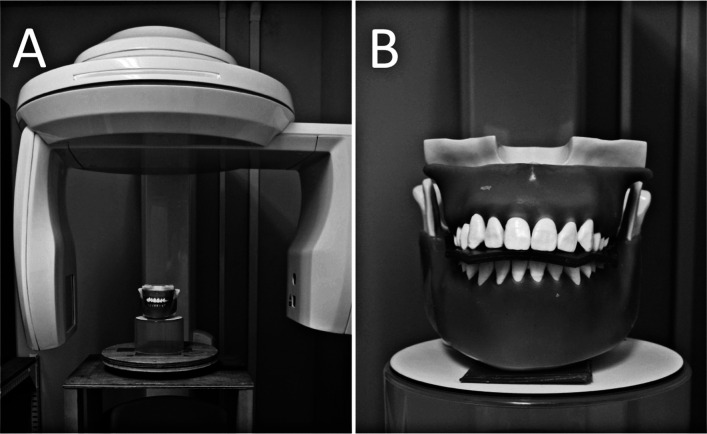
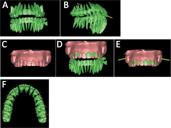
CBCT scans were performed using the Finecube System (Yoshida Dental, Tokyo, Japan) with the following standardized parameters: 90 kV; 4 mA; FOV, 8.20 cm (diameter) × 7.51 cm (height); acquisition time, 19 seconds; 512 images; voxel size, 0.157 × 0.157 × 0.146 mm; CTDIw, 5 mGy (Figure 1A). Three anthropomorphic phantoms (Nissin Dental Product, Kyoto, Japan) comprising artificial bone, teeth, and gingiva with attenuation characteristics similar to human dentition were used to acquire the 3D CBCT dentition images. To obtain fine images from the occlusal surface of the teeth, the phantoms were scanned without interarch contact through separation by a piece of wax (Figure 1B). Based on the 3D CBCT data in DICOM format, 3D dentition images were created with 1200–3071 threshold voxel values in Simplant software (Materialise Dental Japan Inc, Tokyo, Japan; Figure 2A). Virtual column implants (1.8-mm diameter; Figure 2B, yellow columns) were placed between adjacent roots during surgical planning, with precautions taken to protect the tooth roots from damage by the implants. The position data were saved as implantation plans representing the predicted trajectory of the miniscrews.
Figure 1.
The CBCT machine (A) and phantom (B).
Figure 2.
Implant planning process: (A) 3D-image reconstruction of the dentition, (B) virtual implant planning in Simplant software, (C,D) superimposition of surface image with CBCT image, (E) implantation planning on maxilla, (F) 11 anatomical points (red dots) used for superimposition. The green and red images represent the dentition as shown by CBCT scanning and the maxillary surface image of the cast model as shown by 3D laser scanning, respectively.
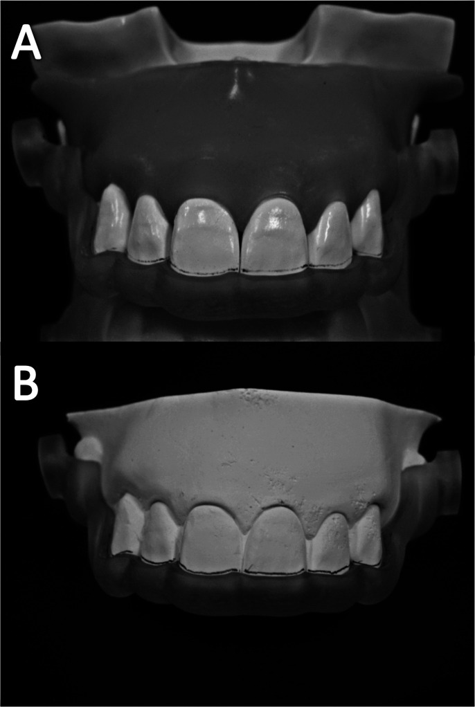
Impressions of the phantoms were taken with an alginate-based material, and cast models of the phantom with special “blockouts” were acquired. The blockout created a space between the stent's inner surface and the artificial gingival surface of the phantom around the insertion sites, so that the stents could be removed from the phantom following miniscrew implantation. The cast models were scanned using a 3D laser scanner (LPX-1200; Roland DG Corporation, Shizuoka, Japan) with a 0.1-mm slice pitch, and the reconstructed surface images (STL files) were exported (Figure 2C). The STL files were then imported into Simplant software and superimposed on CBCT dentition images to acquire the fine 3D dentition images (Figure 2D,E) and to transfer the spatial data of blockouts. Eleven anatomical points on the occlusal surface were used for accurate superimposition of the CBCT and 3D laser-scanned images (Figure 2F). The data for the implantation plan, including the superimposed 3D laser-scanned image and a dental cast of the phantom, were sent to Materialise Dental Japan Inc for the fabrication of the surgical stents in a CAD-CAM process (Figure 3A,B) with photopolymerized resin using a stereolithographic appliance (SLA).
Figure 3.
The fabricated surgical stents constructed using photopolymerized resin and an SLA. The stent fits equally stably in both the phantom (A) and cast models (B).
Surgical Procedure
The samples were divided into two groups: in the stent group, 20 miniscrews were implanted in two phantoms guided by 10 surgical stents; in the freehand group, 10 miniscrews were implanted in one phantom freehand.
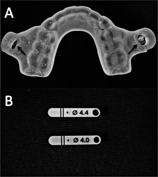
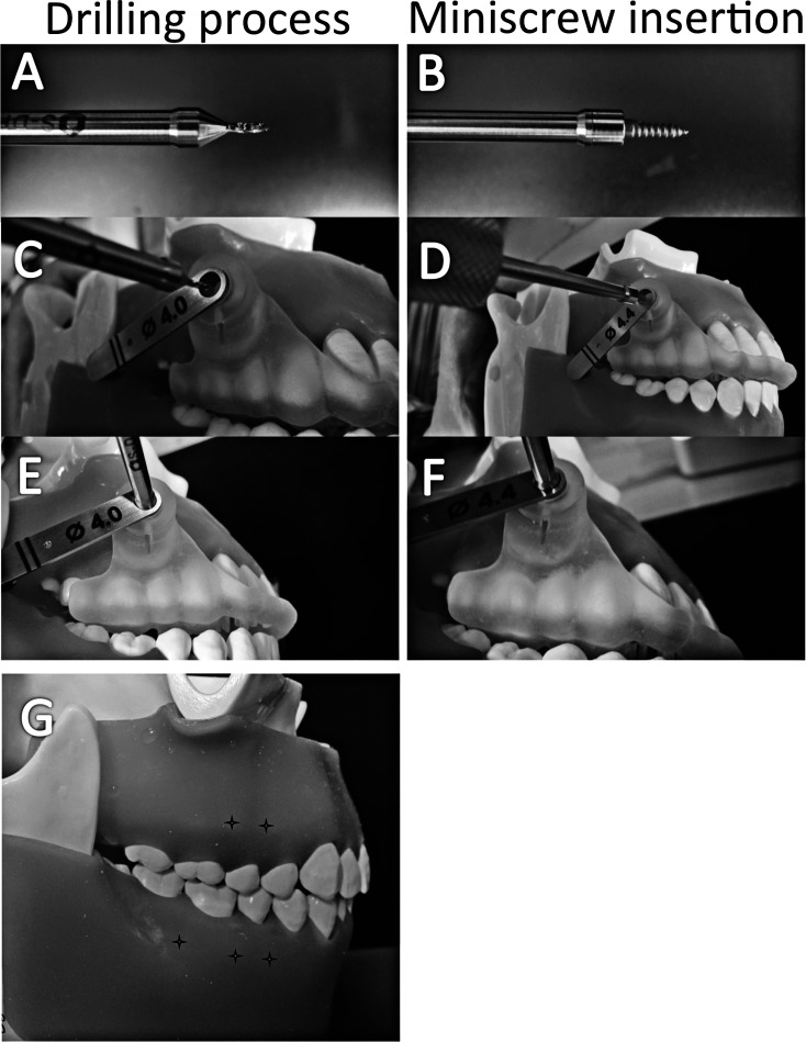
For the stent group, the SurgiGuide system (Materialise Dental Japan Inc), which consists of a surgical stent with universal tubes on each buccal side (Figure 4A, arrows) and two drilling keys (4.0-mm [key #1] and 4.4-mm [key #2] inner diameter; Figure 4B), was used. Self-drilling miniscrews (1.8-mm diameter/1+6 mm; Ortholution, Seoul, Korea) were implanted using the dedicated surgical tools (Figure 5A,B). First, key #1 and pilot drill were inserted into the universal tube to create a 1.0-mm predrilling hole under the guide (Figure 5A,C,E). Key #1 was then replaced by key #2, so that a standard screwdriver tip could then be used to insert the miniscrews (Figure 5B,D,F). The miniscrews were implanted at two to three positions on each side of the maxillary or mandibular posterior arches (Figure 5G).
Figure 4.
The surgical stents fabricated by the SurgiGuide System. (A) The stent with fixed universal tube, (B) two guide keys of diameter 4.0 and 4.4 mm.
Figure 5.
Surgical procedures for miniscrew implantation using the double-key system. (A) Surgical pilot drill, (B) standard hand-driver tip with a miniscrew, (C,E) drilling process, (D,F) miniscrew insertion, (G) insertion points on the phantom model (crosses).
For the freehand group, the distance between the insertion point and adjacent molar cusps was measured in Simplant software to determine the insertion point on the phantom, which was represented by calipers according to the measurements. The pilot drilling and miniscrew insertion angles were frequently checked during the freehand operation by comparing the computer image and the phantom model.
Evaluation of the Accuracy of Miniscrew Implantation
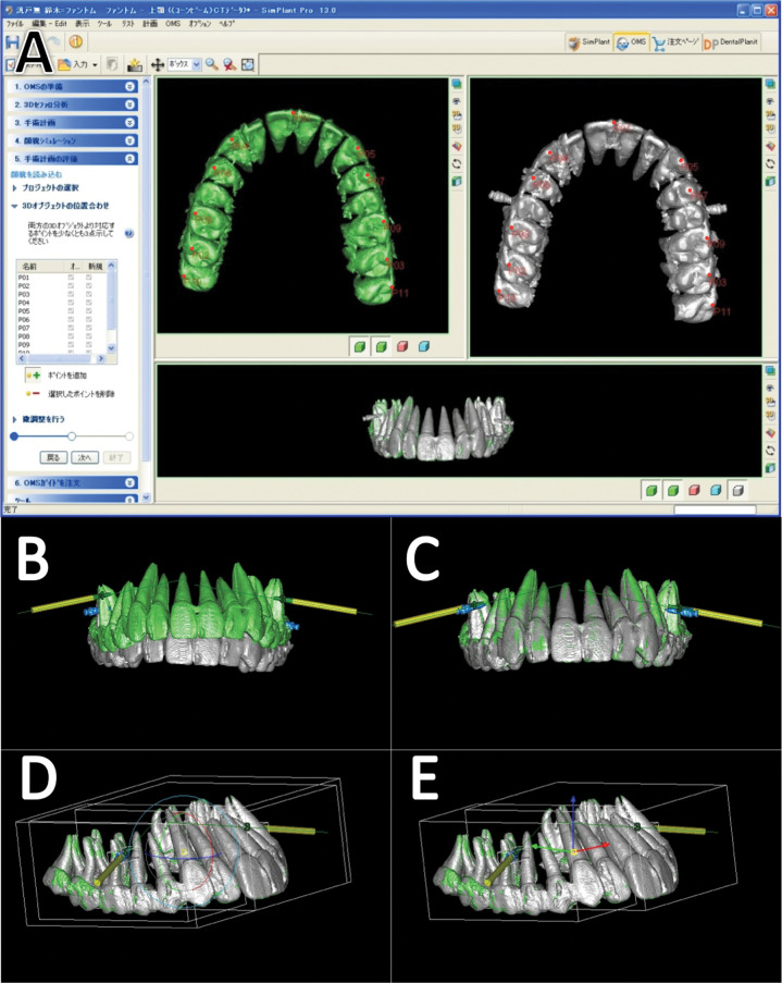
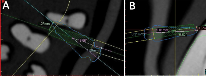
The phantoms were scanned again to obtain postoperative CBCT images (Figure 6A, white), which were then superimposed on the preoperative images (Figure 6A, green), for evaluating the deviation between the virtual and actual implanted position of the miniscrews (Figure 6B–E). Six parameters (coronal, apical, and angular mesiodistal and vertical deviations) were measured in the axial planes (Figure 7A), which were parallel to the occlusal plane and located at the actual miniscrew's corona or apex, and in the cross-sectional planes (Figure 7B), which were parallel to the long axis of the actual miniscrew and perpendicular to the axial plane. Student's t-test (P < .05) was used to analyze the statistical significance of deviation between the two groups, as well as the deviation with and without root contact within the freehand group.
Figure 6.
Superimposition of pre- and postoperative CBCT images. (A) 11 corresponding points (red dots) used for accurate superimposition, (B,C) images before and after superimposition. The green and white images represent the dentition from pre- and postoperative CBCT scanning, respectively. (D, E) Fine adjustment of the superimposition. The yellow columns indicate the virtual implant positions.
Figure 7.
Measurement of deviation at the corona, apex, and angular deviation. (A) Apical/coronal mesiodistal deviation and angular mesiodistal deviation in the axial plane, (B) apical/coronal vertical deviation and angular vertical deviation in the cross-sectional plane. The blue and green/yellow lines indicate the miniscrew and virtual column implant, respectively.
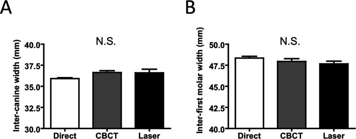
To evaluate the reliability of the 3D CBCT images of the phantoms and the laser scanning 3D images of the cast models, direct measurements using digital calipers (NTD12; Mitutoyo Corporation, Kanagawa, Japan) on one phantom and the measurements for the corresponding distances on 3D images (intercanine width and inter–first molar width) were made. Repeated-measures analysis of variance tests (P < .05) were performed.
Reliability of the Superimposition and Measurements on 3D CBCT
The reliability of superimposition and the reproducibility of the measurements on 3D CBCT images were analyzed using Dahlberg's formula.9 The superimposition and measurements were repeated at 2-day intervals. To determine the superimposition deviations and the difference between two measurements, 72 records for linear measurements and 36 records for angular measurements were selected. The superimposition deviations were 0.017 mm for linear and 0.17° for angular measurements. The measurement errors of pre- and postoperative CBCT images were 0.055 mm for linear and 0.46° for angular measurements.
RESULTS
No significant differences were found between the scanning or measurement methods (Figure 8A,B). The fabricated stents could be maintained stably on the phantoms throughout the implantation process. No root damage was found in the stent group, whereas four out of 10 miniscrews contacted with roots in the freehand group.
Figure 8.
The reliability of direct measurement of phantom, 3D measurement of CBCT-reconstructed images, and 3D laser-scanned images. (A) Inter-canine width, (B) inter-first molar width. Each column represents mean ± standard deviation (mm). N.S. indicates not significant.
In the stent group, deviations in the mesiodistal and vertical directions were 0.15 ± 0.09 and 0.19 ± 0.19 mm at the corona, respectively, and 0.28 ± 0.23 and 0.33 ± 0.25 mm at the apex, respectively. Angular deviations in the mesiodistal and vertical directions were 1.47° ± 0.56° and 2.13° ± 1.48°, respectively. The corresponding results in the freehand group were 0.48 ± 0.46 mm, and 0.94±0.87 mm (corona), 0.81 ± 0.61 mm and 0.78 ± 0.49 mm (apex), and 7.49° ± 6.09° and 6.31° ± 3.82°, respectively. The deviations in the stent group were significantly lower than those in the freehand group for all six parameters (Table 1).
Table 1.
Miniscrew Implantation Deviation in the Stent and Freehand Groupsa
In the freehand group, the apical mesiodistal deviation in miniscrews without root contact was significantly less than those with root contact (Table 2).
Table 2.
Miniscrew Implantation Deviation With or Without Root Contacta
DISCUSSION
Accuracy of Stent-Guided Implantation
Our results indicate that the deviations in miniscrew implantation were significantly lower in the stent group compared with the freehand group. No miniscrews in the stent group damaged the tooth roots, proving the usefulness of the stents. Most notably, the angular deviations were significantly less in the stent group, suggesting that CBCT image-based stents could support predictable implantation.
A number of reports have been published on the accuracy of miniscrew implantation based on different types of guide system; with medical CT and rapid-prototyping templates, the mesiodistal deviation was 0.42 ± 0.13 mm at the apex, and the angular deviation was 1.2° ± 0.43°.8 Another system, using a 2D radiography–based 3D surgical guide, showed a deviation of 0.6 ± 0.5 mm and 2.0 ± 0.4 mm at the miniscrew head and point, respectively.3 Although implantation deviations in different studies cannot be compared directly, because the results differed based on different research designs, our results appear to be in the range of or even lower than those of previous reports.
The Origin of Stent-Guided Implantation Deviation
Deviation when using stent guides may occur through a number of errors generated throughout the process, one of which originates during image acquisition. A 3D reconstructed model's image quality is dependent on the CBCT scanner, scanning parameters, and reconstruction settings10; during 3D image reconstruction, the threshold values in the software are critical to the geometric accuracy and quality of the images. To evaluate the reliability of 3D dentition images, the distance between key references on the phantoms and their 3D images was measured. No statistical differences were observed between the measurements on CBCT images, laser scanning images, and direct measurement when the 3D CBCT dentition images were depicted with a threshold value of 1200–3071. However, the artifacts were apparent in the buccal interproximal space of the dental image with the threshold. Therefore, we superimposed the laser scanning 3D images on the CBCT images to obtain dentition images of greater clarity, which approximated to the actual dentition of the phantom.
Deviations can also be generated from errors in the stent fabrication process. A previous report indicated that the deviation between the original and SLA models was 0.56% ± 0.39%,11 suggesting that the fabrication process is unlikely to contribute significantly to error. When our stents were placed in the original phantom as well as the corresponding cast model, all could be accurately positioned with stability, particularly during the implantation processes on the phantom (Figure 5), which proves that the impression-taking process and stent fabrication with SLA are acceptable. To reproduce the accurate positioning and stability of the stent, we extended the area of the stent to both sides of the dental arch.
In the implantation process, the clearance between the surgical tools and guide keys is necessary to avoid excessive friction and binding of components during the implantation procedure,12 but on the other hand, excessive clearance will result in unfavorable deviation. In our research, the double-key system, comprising a stent with two fixed universal tubes and two removable keys, was utilized. The clearance between the keys and surgical tools was 0.02–0.05 mm, which allowed accomplishment of the drilling and insertion processes without excessive friction.
Clinical Significance of the Stents
The likelihood of safe and stable miniscrew implantation is influenced by three clinical factors: the morphology and quality of teeth and bone (host factor), the conformation of the implant (material factor), and the placement technique (operator factor). Based on studies on host factor,13–15 a safe zone for miniscrew insertion has been reported. Because of the limited width of the safe zone, many suggestions on miniscrew diameter and design, placement sites, and angulation of insertion have also been made. Decreasing the screw diameter and length is a method of reducing the root damage risk13,15; however, implant fracture and low stability are frustrating when using thin miniscrews.
Therefore, improving the accuracy of miniscrew placement technique is vital for the implantation safety. Generally, angulated placement is strongly recommended in the intermolar region, especially in the maxilla13,16; however, we placed miniscrews with lower angulation (0°–10° from the occlusal plane) to simulate difficult cases to be implanted. Indeed, the interradicular distance of the five positions chosen in the phantoms was much narrower (<2.0–2.5 mm) than that normally observed in patients. This could be the reason why we found a high probability of root damage in the freehand group, although the operation was performed with great care.
Our results show the apical mesiodistal deviation of miniscrews without root contact to be significantly lower than that of miniscrews with root contact in the freehand group (Table 2). It proved that among the six parameters, the apical mesiodistal deviation is the key indicator for root contact.
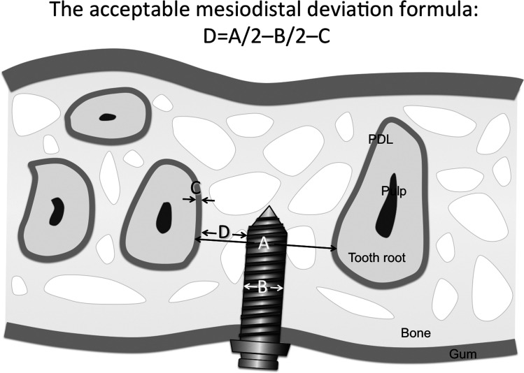
For the individual patient, an acceptable mesiodistal deviation could be calculated using the formula shown in Figure 9. By comparison of the acceptable deviation with the predicted deviation of our stents, the possibility of root damage could be evaluated. If the closest interradicular distance is 3.5 mm, the miniscrew diameter is 1.6 mm, and the periodontal ligament width is 0.2 mm, the acceptable deviation will be 0.75 mm according to the formula. On the other hand, the apical deviation with 95% probability (mean ± 2 SD) will be lower than 0.74 mm in the mesiodistal direction if our stents are utilized. If the safety margin is poor, the miniscrew diameter, insertion position, or insertion angle may be altered.
Figure 9.
The acceptable mesiodistal deviation formula: D = A/2 – B/2 – C (D indicates acceptable apical mesiodistal deviation; A, closest interradicular distance; B, miniscrew diameter; C, periodontal ligament width). PDL indicates periodontal ligaments.
Although a new method for accurate orthodontic miniscrew implantation was introduced in our in vitro research, there were several limitations of the results to be applied in vivo. For example, the phantoms do not represent the various types of malocclusions, and the threshold voxel value of the phantom does not match completely with that of living dental and soft tissues. An additional cost and time factor for stent preparation would also need to be taken into consideration.
CONCLUSIONS
3D CBCT image-based SLA-fabricated surgical stents with sufficient accuracy for miniscrew implantation could be made available.
This method may be more beneficial when patients have insufficient space for freehand insertion: for example, patients with multiple impacted teeth or with limited interradicular distance on account of an extended maxillary sinus.
Acknowledgments
This research was supported by Japan China Medical Association, KAKENHI (Grants-in-Aid for Scientific Research; 21592591 to SS), and a grant from the Japanese Ministry of Education, Global Center of Excellence (GCOE) Program.
REFERENCES
- 1.Wu J. C, Huang J. N, Zhao S. F, Xu X. J, Xie Z. J. Radiographic and surgical template for placement of orthodontic microimplants in interradicular areas: a technical note. Int J Oral Maxillofac Implants. 2006;21:629–634. [PubMed] [Google Scholar]
- 2.Bae S. M, Park H. S, Kyung H. M, Kwon O. W, Sung J. H. Clinical application of micro-implant anchorage. J Clin Orthod. 2002;36:298–302. [PubMed] [Google Scholar]
- 3.Suzuki E, Suzuki B. Accuracy of miniscrew implant placement with a 3-dimensional surgical guide. J Oral Maxillofac Surg. 2008;66:1245–1252. doi: 10.1016/j.joms.2007.08.047. [DOI] [PubMed] [Google Scholar]
- 4.Estelita S, Janson G, Chiqueto K, Janson M, de Freitas M. Predictable drill-free screw positioning with a graduated 3-dimensional radiographic-surgical guide: a preliminary report. Am J Orthod Dentofacial Orthop. 2009;136:722–735. doi: 10.1016/j.ajodo.2007.12.028. [DOI] [PubMed] [Google Scholar]
- 5.Miyazawa K, Kawaguchi M, Tabuchi M, Goto S. Accurate pre-surgical determination for self-drilling miniscrew implant placement using surgical guides and cone-beam computed tomography. Eur J Orthod. 2010;32:735–740. doi: 10.1093/ejo/cjq012. [DOI] [PubMed] [Google Scholar]
- 6.Kim S, Choi Y, Hwang E, Chung K, Kook Y, Nelson G. Surgical positioning of orthodontic mini-implants with guides fabricated on models replicated with cone-beam computed tomography. Am J Orthod Dentofacial Orthop. 2007;131(suppl 4):S82–S89. doi: 10.1016/j.ajodo.2006.01.027. [DOI] [PubMed] [Google Scholar]
- 7.Kim S, Kang J, Choi B, Nelson G. Clinical application of a stereolithographic surgical guide for simple positioning of orthodontic mini-implants. World J Orthod. 2008;9:371–382. [PubMed] [Google Scholar]
- 8.Liu H, Liu D. X, Wang G, Wang C. L, Zhao Z. Accuracy of surgical positioning of orthodontic miniscrews with a computer-aided design and manufacturing template. Am J Orthod Dentofacial Orthop. 2010;137(6):728.e1–728.e10. doi: 10.1016/j.ajodo.2009.12.025. [DOI] [PubMed] [Google Scholar]
- 9.Dahlberg G. Statistical Methods for Medical and Biological Students. New York, NY: Interscience Publications; 1940. [Google Scholar]
- 10.Loubele M, Maes F, Jacobs R, van Steenberghe D, White S, Suetens P. Comparative study of image quality for MSCT and CBCT scanners for dentomaxillofacial radiology applications. Radiat Prot Dosimetry. 2008;129:222–226. doi: 10.1093/rpd/ncn154. [DOI] [PubMed] [Google Scholar]
- 11.Choi J. Y, Choi J. H, Kim N. K, et al. Analysis of errors in medical rapid prototyping models. Int J Oral Maxillofac Surg. 2002;31:23–32. doi: 10.1054/ijom.2000.0135. [DOI] [PubMed] [Google Scholar]
- 12.Park C, Raigrodski A, Rosen J, Spiekerman C, London R. Accuracy of implant placement using precision surgical guides with varying occlusogingival heights: an in vitro study. J Prosthet Dent. 2009;101(6):372–381. doi: 10.1016/S0022-3913(09)60080-9. [DOI] [PubMed] [Google Scholar]
- 13.Kim S. H, Yoon H. G, Choi Y. S, Hwang E. H, Kook Y. A, Nelson G. Evaluation of interdental space of the maxillary posterior area for orthodontic mini-implants with cone-beam computed tomography. Am J Orthod Dentofacial Orthop. 2009;135:635–641. doi: 10.1016/j.ajodo.2007.06.013. [DOI] [PubMed] [Google Scholar]
- 14.Lim J. E, Lee S. J, Kim Y. J, Lim W. H, Chun Y. S. Comparison of cortical bone thickness and root proximity at maxillary and mandibular interradicular sites for orthodontic mini-implant placement. Orthod Craniofac Res. 2009;12:299–304. doi: 10.1111/j.1601-6343.2009.01465.x. [DOI] [PubMed] [Google Scholar]
- 15.Poggio P. M, Incorvati C, Velo S, Carano A. “Safe zones”: a guide for miniscrew positioning in the maxillary and mandibular arch. Angle Orthod. 2006;76:191–197. doi: 10.1043/0003-3219(2006)076[0191:SZAGFM]2.0.CO;2. [DOI] [PubMed] [Google Scholar]
- 16.Lee K, Joo E, Kim K, Lee J, Park Y, Yu H. Computed tomographic analysis of tooth-bearing alveolar bone for orthodontic miniscrew placement. Am J Orthod Dentofacial Orthop. 2009;135:486–494. doi: 10.1016/j.ajodo.2007.05.019. [DOI] [PubMed] [Google Scholar]


