Abstract
Chipless RFID has gained prominence due to its application versatility and cost and complexity advantages over traditional RFID. However, chipless RFID tags are typically designed for a specific application instead of being deployable for a multitude of applications. In this paper, a new approach to adaptable chipless RFID tag is proposed that can be optimized for a variety of applications, including materials characterization with tags as embedded sensors. Additionally, the designed approach renders tags that can be interrogated with a linearly polarized probe and achieves bit densities up to 27.57 bits/cm2.
Keywords: Chipless RFID, bit density, spiral resonators
I. Introduction
Chipless RFID has gained popularity over the last decade due to its significant potential for being used in many applications and its cost and complexity advantages over traditional RFID. Chipless RFID tags, unlike their active and passive counterparts, do not require a power source and do not store their binary ID codes on memory chips [1]. Rather, codes are derived from the tag’s high-frequency response such as its radar cross-section (RCS), complex reflection coefficient (S11), or time delay [1–5].
There are two primary types of chipless RFID tags: those designed for identification and for sensing applications. The associated binary code for identification type tags results from the tag structure (e.g., antenna, frequency selective structure, transmission line type, etc.). When the structure is modified, the code is modified, creating different codes for different tags. Sensing type tags correlate a change in tag response to a change in the environment (i.e., a change in temperature, humidity, gas concentration, etc.) and rarely assign a binary code to the tag response. However, a binary code can be assigned to sensing type chipless RFID tag responses in order to better quantify the change in response due to the change in environment [1–5]. For both types of tags, information density, defined as the number of bits per square centimeter, is an important parameter. For identification applications a high information density is usually sought and for sensing applications the information density should be optimized for the particular application at hand. However, bit density is also dependent on the code generation method used, with there being three popular encoding methods, as described in [6–9]. One popular encoding method for identification type chipless RFID tags is to assign each notch in the RCS response a 1, creating a binary code with as many 1’s as there are notches. When the structure of the tag is modified in a way that results in a notch being removed from the response, a 0 replaces the associated 1 in the code [6]. This is considered the most conservative encoding method in that it results in the shortest codes and lower bit densities. Another method is to assign 1’s to notches and 0’s elsewhere [9]. Due to the way identification type and sensing type chipless RFID tags are used, tag adaptability is desirable, namely; the ability to adaptively change the tag design and hence its code to suite an application Additionally, the optimal coding method is application dependent.
In this paper, a new adaptable chipless RFID tag that can be used for both identification and sensing applications is proposed. This tag is less than 1 cm in diameter for use in K- and Ka-band (18–40 GHz) and can be adapted into different configurations using different element “classes” of spiral and ring resonators to achieve bit densities of up to 27.57 bits/cm2 using the most conservative code generation method.
II. Chpless Tag
A. Design and Simulations
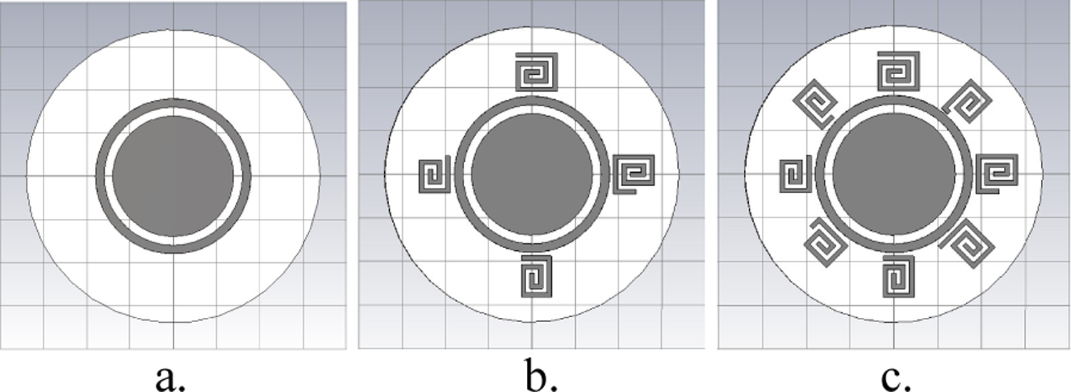
The proposed tag was modeled and its response simulated using the full wave CST Microwave Studio®. This tag consists of a ground plane-backed substrate disk with a circular patch. Classes of spiral resonators and ring resonators can be added and removed in order to adjust the RCS response of the tag for a given application. The diameter of the substrate disk is 0.68 cm and it is made of Taconic TLX-9 (εr=2.5 and tanδ=0.0019). Fig. 1a shows the tag in one of its simplest configurations, namely only a 1-ring resonator, and Figs. 1b and 1c show other tag configurations.
Figure 1:

Tag models in CST Microwave Studio®.
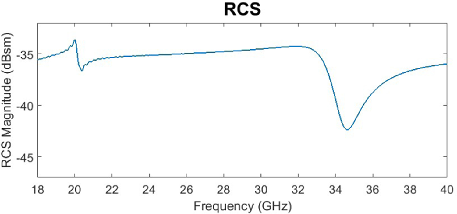
The response of the tag was simulated in a monostatic radar configuration. A linearly polarized plane wave was used to interrogate the tag and a RCS probe placed 10 cm in front of the tag was used to measure the response with the same polarization. The ability to send a wave at the tag and receive the response with the same polarization allows for a simpler tag reader system, increasing the utility of the tag. Fig. 2 shows the RCS response for the tag configuration presented in Fig. 1a. By adding more ring resonators, more resonances are created, resulting in a tag similar to that proposed in [6].
Figure 2:

RCS response of the tag shown in Fig. 1a.
B. Tag Configurations
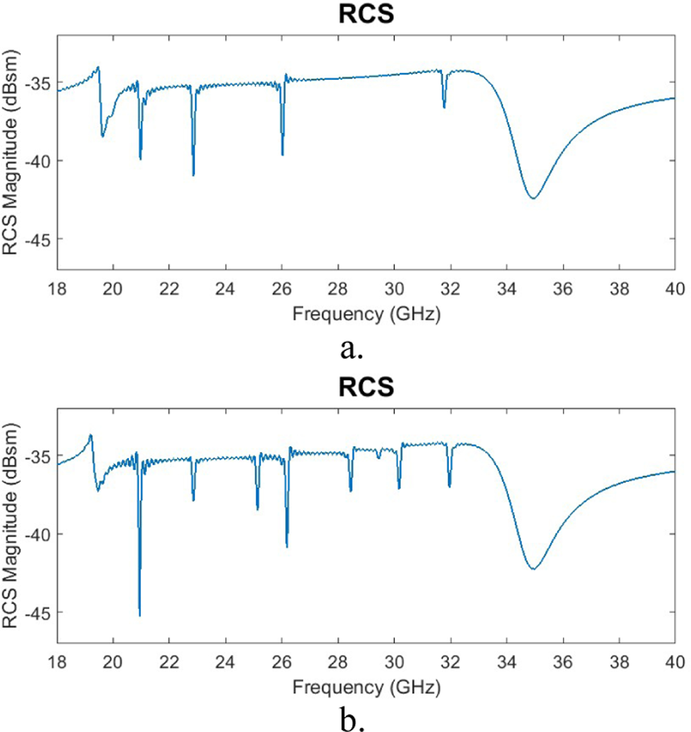
Following the development of the tag shown in Fig. 1a, other configurations were considered by adding spiral resonators as another element class. First, 4 spiral resonators of different lengths were designed to have their resonances spaced between 20 GHz and 35 GHz, the resonance frequencies of the ring resonator and circular patch, respectively. Each spiral element being a different length means that the effective inductance and capacitance of each spiral is different, causing them to have different resonance frequencies. By making a spiral longer, the inductance and capacitance of the spiral increase and the resonance frequency occurs at a lower frequency than it would if the spiral were shorter [10]. Next, 4 more spirals were designed to introduce 4 more resonances. Figs. 1b and 1c shows the 4 and 8 spiral configurations of the tag, while Fig. 3 shows the RCS responses of these two tag configurations.
Figure 3:

RCS responses: a) 4 spiral tag response b) 8 spiral tag response.
As more spirals are added to the tag, the bit density increases since more notches are introduced. Fig. 3b also shows that adding more spirals causes the RCS response associated with the original 4 spirals to change slightly. These changes, mostly due to tag element interactions, need to be considered as the tag is adapted for applications. The bit density for the 8 spiral tag using the most conservative coding method is 27.57 bits/cm2, which is one of the highest reported bit densities. This tag also works well for the coding method of assigning 1’s to notches and 0’s elsewhere, since its notches are very distinct. If this method is used, the code for the 4 spiral tag is [11010010000011] and the code for the 8 spiral tag is [11010110111011], resulting in a bit density of 38.57 bits/cm2.
III. Conclusion
This paper proposes a new adaptable chipless RFID tag. The tag can be adapted by adding or removing element classes to adjust the RCS response and code of the tag. In this way, the tag can be optimized for the application it is being used for. The tag can also be interrogated with a linearly polarized probe and is capable of having a very high bit density. Future work will include developing more element classes to make the tag even more versatile and developing element class combinations that allow the tag to be optimized for parameters such as, orientation independence, tag/reader alignment robustness, reader bandwidth, and reader capability (i.e., the number of frequency points the reader is capable of measuring) so that all notches are detected and codes are correctly generated. Additionally, this tag development approach will be explored further for materials characterization applications that use the tag as an embedded sensor, advancing this method as a nondestructive testing (NDT) technique.
Acknowledgment
This work was supported by a NASA Space Technology Research Fellowship.
References
- [1].Preradovic S (2012). Multiresonator-based chipless rfid. Springer, Chapter 2. [Google Scholar]
- [2].Habib A, Afzal MA, Sadia H, Amin Y and Tenhunen H, “Chipless RFID tag for IoT applications,” 2016 IEEE 59th International Midwest Symposium on Circuits and Systems (MWSCAS), Abu Dhabi, 2016, pp. 1–4. [Google Scholar]
- [3].Ramos A, Lazaro A and Girbau D, “Time-coded chipless sensors to detect quality of materials in civil engineering,” 2015 9th European Conference on Antennas and Propagation (EuCAP), Lisbon, 2015, pp. 1–4. [Google Scholar]
- [4].Occhiuzzi C, Paggi C and Marrocco G, “Passive RFID Strain-Sensor Based on Meander-Line Antennas,” in IEEE Transactions on Antennas and Propagation, vol. 59, no. 12, pp. 4836–4840, Dec. 2011 [Google Scholar]
- [5].Khaliel M, Fawky A, El-Awamry A, Mahmoud AE and Kaiser T, “Printable, high coding capacity chipless RFID tags for low-cost item tagging,” 2017 IEEE 14th International Conference on Networking, Sensing and Control (ICNSC), Calabria, 2017, pp. 351–355. [Google Scholar]
- [6].Islam MA, Yap Y, Karmakar N and Azad AKM, “Orientation independent compact chipless RFID tag,” 2012 IEEE International Conference on RFID-Technologies and Applications (RFID-TA), Nice, 2012, pp. 137–141. [Google Scholar]
- [7].Amin EM, Saha JK and Karmakar NC, “Smart Sensing Materials for Low-Cost Chipless RFID Sensor,” in IEEE Sensors Journal, vol. 14, no. 7, pp. 2198–2207, July 2014. [Google Scholar]
- [8].Huang H. f. and Su L; “A Compact Dual-Polarized Chipless RFID Tag by Using Nested Concentric Square Loops,” in IEEE Antennas and Wireless Propagation Letters, vol. 16, pp. 1036–1039, 2017. [Google Scholar]
- [9].Khaliel M, El-Awamry A, Fawky A and Kaiser T, “Long reading range chipless RFID system based on reflectarray antennas,” 2017 11th European Conference on Antennas and Propagation (EUCAP), Paris, 2017, pp. 3384–3388. [Google Scholar]
- [10].Santos-Souza GT, Alves A. A. d. C., Bravo-Roger LL and Hernandez-Figueroa HE, “Numerical determination of frequency guard band resonances for Chipless RFID Tags,” 2014 IEEE Brasil RFID, Sao Paulo, 2014, pp. 10–12. [Google Scholar]


