

Abstract

In recent years, cyclo-N5– has attracted extensive attention because all-nitrogen high-energy-density materials (HEDMs) have been expected to reach a TNT equivalent of over 3.0. However, for cyclo-N5–-containing HEDMs, the stabilization mechanism has remained enigmatic. In this study, two typical cyclo-N5–-containing metal hydrates, [Na(H2O)(N5)]·2H2O (Na-cyclo-N5–) and [Mg(H2O)6(N5)2]·4H2O (Mg-cyclo-N5–), are selected to gain insights into the factors affecting their stability by the first-principles method. Both binding/lattice energy calculations and density of states analysis show that Mg-cyclo-N5– is more stable than Na-cyclo-N5–. Hydrogen bonding is the main stabilization mechanism for stabilizing crystals and cyclo-N5–. Two types of hydrogen bonds, O–H···O and O–H···N, are clarified, which construct a 3D hydrogen bond network in Mg-cyclo-N5– and an intralayer 2D hydrogen bond network in Na-cyclo-N5–. Moreover, nonuniform stress causes distortion of cyclo-N5–. Comparing the two samples, the distortion degree of cyclo-N5– is higher in Na-cyclo-N5–, which indicates that cyclo-N5– decomposition is easier. These findings will enhance the future prospects for the design and synthesis of cyclo-N5–-containing HEDMs.
1. Introduction
Nitrogen-rich high-energy-density materials (HEDMs) are gaining popularity due to their excellent energy storage capacity and environmentally friendly decomposition products.1−5 Because of possessing a large number of N–N, N=N, and N≡N bonds, nitrogen-rich materials contain higher energy (38.2, 99.9, and 224.9 kcal mol–1 for N–N, N=N, and N≡N, respectively) than traditional CHON explosives (C–C, C–N, C=C, and C≡C bonds).6 In the past few decades, a few nitrogen-rich HEDMs, such as azide salts: N3–,7,8 N3+,7,8 N4+,9 and N5+10−12 salts; metastable molecules: tetraazatetrahedrane (N4),13 hexaazabenzene (N6),13,14 and octaazacubane (N8);13 single-bonded cubic form of nitrogen: cg–N,15 and so forth, have been researched and synthesized. Several theoretical studies had also contributed to the synthesis of more diversified stable nitrogen-rich HEDMs.16−18
Among the nitrogen-rich HEDMs, the five-membered cyclo-N5– ring has a unique structure and a greater ability to store energy compared to the azide ions. However, the synthesis of cyclo-pentazole (cyclo-N5–) HEDMs, which are stable in common conditions, remains a challenge. In fact, attempts were made to synthesize cyclo-N5– at a very early stage.19−21 However, cyclo-N5– obtained from the experimentally synthesized scheme is short-lived, unstable under normal conditions, and extremely susceptible to decomposition into dinitrogen (N2) and N3– (the decomposition of cyclo-N5– into N2 and N3– is exothermic by 14.3 kcal mol–1, and the activation energy for this decomposition is 27.2 kcal mol–1.4). Therefore, a stabilization mechanism of cyclo-N5– has always been a key issue in such exploration in cyclo-N5– HEDMs. Until recently, an experimentally workable method was used for the synthesis of stable cyclo-N5–-containing HEDMs. In 2017, the first stable nonmetallic cyclo-N5– salt in common conditions, (N5)6(H3O)3(NH4)4Cl (PHAC), was synthesized by Zhang et al.22 It is a brilliant achievement after more than 50 years of unremitting effort and opens the door to the extensive development of pentazolate chemistry.23 However, 1.340 g cm–3 density of this material and dilution with nonenergetic components did not meet the demands of HEDMs. To produce pentazolate (cyclo-N5–) compounds with relatively high performance while maintaining thermal stability, metal ions and/or high-nitrogen-containing cations were investigated as cyclo-N5– traps.24 Then, [Co(N5)2(H2O)4]·4H2O, an air-stable orange metal complex, was synthesized by reacting (N5)6(H3O)3(NH4)4Cl and [Co(NO3)2]·6H2O at room temperature.24 Immediately after that, a series of stable high-energy metal pentazolate hydrates, [Na(H2O)(N5)]·2H2O (Na-cyclo-N5–), [M(H2O)4(N5)2]·4H2O (M = Mn, Fe and Co), and [Mg(H2O)6(N5)2]·4H2O (Mg-cyclo-N5–), was synthesized by Xu et al.25 Furthermore, they also synthesized some other nitrogen-rich HEDMs within cyclo-N5–, such as [Zn(N5)2(H2O)4]·4H2O26 and three anhydrous and metal-free energetic salts.27
Among such cyclo-N5– materials, cyclo-N5– metal hydrates are particularly interesting. In the classical theoretical calculation method (Kamlet–Jacobs theory) of detonation properties, such as detonation pressure, detonation velocity, and detonation heat, density is a basic parameter. Synthesizing energetic materials (EMs) with higher density is an important way to improve the detonation performance. Therefore, the addition of metal elements in cyclo-N5– metal hydrates will not only effectively increase the density but also help obtain the cyclo-N5– EMs with relatively high performance. How to sustain or even improve the stability of metal hydrate is very necessary for its subsequent application. In the synthesized cyclo-N5– metal hydrate mentioned above, there are two ways to capture cyclo-N5–: one is that the metal cations are coordinated with cyclo-N5–; the other is that the metal cations are not directly connected with cyclo-N5– but form hydrogen bonds (HBs) with cyclo-N5– through surrounding coordination H2O molecules. Mg-cyclo-N5– is only one of these metal hydrates in which cyclo-N5– are nonbonding with the metal atoms.25 Metal atoms in other metal hydrates are all bonded with cyclo-N5–, such as Na-cyclo-N5–, [M(H2O)4(N5)2]·4H2O (M = Mn, Fe, and Co),25 and [Zn(N5)2(H2O)4]·4H2O.26 However, the stabilization mechanism of such novel cyclo-N5– metal hydrates has not been explored in depth so far.
Among the metal hydrates, [Na(H2O)(N5)]·2H2O (Na-cyclo-N5–) and [Mg(H2O)6(N5)2]·4H2O (Mg-cyclo-N5–) are not only the representatives of two types of stabilizing cyclo-N5– (whether the cyclo-N5– form coordination bonds with metal atoms), but also two typical cyclo-N5– precursors. As reported, Na-cyclo-N5– was the first metal hydrate successfully synthesized, while the other four cyclo-N5– energetic metal hydrates were synthesized by substituting Na+ therein.25 The 3D framework metal hydrate, [Na8(N5)8(H2O)3]n, was also synthesized by Na-cyclo-N5–.28 Therefore, Na-cyclo-N5– is considered to be a vital precursor for the synthesis of metal hydrates. AgN5 was synthesized reactively by adding AgNO3 to Mg-cyclo-N5–.29 In addition, a series of nonmetallic cyclo-N5–-containing energetic salts, such as NH4N5, NH3OHN5, and N2H5N5, had also been synthesized from Mg-cyclo-N5–.30 Obviously, Mg-cyclo-N5– can also act as a precursor to form cyclo-N5–-containing compounds, especially for nonmetallic cyclo-N5– energetic salts. Therefore, the two representative samples, Na-cyclo-N5– and Mg-cyclo-N5–, are selected to explore the factors affecting their stability.
A HB network is considered the main stabilization factor for nonmetallic cyclo-N5– energetic salts.31 However, for such cyclo-N5– metal hydrates, the stabilization mechanism is unclear, and the related investigation is lacking. In the present work, therefore, we employed the first-principles method to investigate the crystalline packing and stability of Na-cyclo-N5– and Mg-cyclo-N5–.32−34 Both formation/binding energy calculations and density of states (DOS) analysis show that Mg-cyclo-N5– is more stable than Na-cyclo-N5–. In Na-cyclo-N5–, cyclo-N5– is stabilized by two Na ↔ N ion bonds and three O–H···N HBs. In Mg-cyclo-N5–, cyclo-N5– is completely stabilized by weak interaction: five O–H···N HBs and π-π stacking interactions. Instead of enhancing the stability of Na-cyclo-N5–, the Na ↔ N ion bonds make cyclo-N5– nonuniformly stressed, resulting in its easy decomposition. The five HBs in Mg-cyclo-N5– make cyclo-N5– uniformly stressed and less distorted, which improves its stability. In addition, the 2D HB network in Na-cyclo-N5– and the 3D HB network in Mg-cyclo-N5– are of great significance to enhance the stability. The 3D HB network is superior to the 2D HB network. In summary, we gain insights into the stabilization mechanism from cyclo-N5–-containing HEDMs that have been successfully prepared and frequently used, and our findings will provide a good reference for the future design and synthesis of such novel, stable, cyclo-N5–-containing HEDMs.
2. Computational Methods
All the first-principle calculations and lattice dynamics calculations were performed with a self-developed package, the High Accuracy atomistic Simulation package for Energetic Materials (HASEM).32,33 The reliability of the HASEM program to describe the structures, energetics, dynamics, mechanical properties, detonation performance, and sensitivity of EM crystals has been extensively verified by comparison of the results with experiments and with CCSD(T) results.33−35,39 To better verify its reliability in describing the noncovalent interactions and structure of the molecules in this paper, we computed CCSD(T) results for comparison. As shown in Table 1, we selected cluster models of the two samples studied in this paper and calculated their energy with CCSD(T) and HASEM. The level of CCSD(T) in terms of the basis set is def2-QZVP. The calculation level of HASEM is Perdew–Burke–Ernzerhof (PBE), and D3-BJ intermolecular dispersion correction was adopted. Binding energy was calculated according to formula 1 in Section 3.1. It can be seen that the errors between the results of HASEM and CCSD(T) were very small, approximately −1%, which was sufficient to illustrate the accuracy of the calculated HASEM results.
Table 1. Comparison between CCSD(T) and HASEM.
| cluster structure | method | binding energy (kcal mol–1) | error (%) | |
|---|---|---|---|---|
| Na(H2O)(N5) | CCSD(T) | –94.82 | –1.25 | |
| HASEM | –93.63 | |||
| Mg(H2O)6(N5)2 | CCSD(T) | –95.42 | –1.04 | |
| HASEM | –94.43 |
The two Na-cyclo-N5– and Mg-cyclo-N5– bulk materials were simulated using a 1 × 1 × 1 unit cell. Figure 1 shows the bulk models of Na-cyclo-N5– and Mg-cyclo-N5–. The Na-cyclo-N5– models along a and c directions are shown in Figure 1a,b, respectively. In Na-cyclo-N5–, there are totally 60 atoms: 4 Na+, 4 N5–, and 12 H2O. Five N atoms in cyclo-N5– are perfectly coplanar along the b axis. Cyclo-N5– rings are directly connected to Na and form N ↔ Na ion bonds. Na is a six-coordination atom in Na-cyclo-N5–, which is bonded with two cyclo-N5– and four H2O molecules. Figure 1c,d show the Mg-cyclo-N5– models along the a and c axes, respectively. In Mg-cyclo-N5–, there are 41 atoms: 1 Mg2+, 2 N5–, and 10 H2O. Five N atoms in cyclo-N5– are also coplanar. cyclo-N5– are not directly bonded with Mg. Similar to Na-cyclo-N5–, in Mg-cyclo-N5–, Mg is also a six-coordination atom, and each Mg is bonded with six H2O molecules.
Figure 1.

Structure models of Na-cyclo-N5– and Mg-cyclo-N5–. (a, b) Views of the Na-cyclo-N5– model, along a and c axes, respectively. (c, d) Views of the Mg-cyclo-N5– model, along a and c axes, respectively. Na is shown in yellow, Mg is shown in orange, O is shown in red, N is shown in blue, and H is shown in white.
The specific settings for the structure optimization of these two crystals are set as follows. Monkhorst-Pack k-point nets of 3 × 2 × 3 and 3 × 3 × 3 were chosen to sample the reciprocal space. Electronic state occupancy obeys the Methfessel and Paxton distribution.36 General gradient approximation with a PBE functional was adopted to describe the electron correlation.37−39 Core electrons were replaced by nonlocal norm-conserving pseudopotentials,40,41 and the valence electrons were described by linear combinations of 18 numerical pseudoatomic orbitals. The large number of valence electron orbitals can ensure that the valence electrons have enough transition space, so that higher energy calculation accuracy can be achieved. The cutoff energy was chosen to be 6802.9 eV to ensure the convergence accuracy of the electrons. D3-BJ intermolecular dispersion correction was adopted. The initial lattice parameters and atomic coordinates obtained from single-crystal X-ray diffraction analysis are used as inputs for geometric optimization based on the conjugate gradient method. The optimization will be accomplished by following the condition that charge density matrix convergence criterion limit is at 5 × 10⁻⁶ and energy convergence criterion is at 10–4 eV. Moreover, the simulated structure was finally optimized when the residual forces were less than 0.04 eV/Å and the stress components were less than 0.01 GPa. The simulated structures of Na-cyclo-N5– and Mg-cyclo-N5– (Figure 1 and Table 2) show satisfactory agreement with the characterized structure by X-ray diffraction, with the discrepancy of the volume at 0.2 and −2.5%, the discrepancy of lattice vectors at ∼1 and ∼3%, and the discrepancy of density at 0.1 and 2.8%. It can be seen that the error between the result calculated by HASEM and the experimental data was very small, which was sufficient to illustrate the accuracy of the calculated HASEM results.
Table 2. Crystal Data for Na-cyclo-N5– and Mg-cyclo-N5–
| a (Å) | b (Å) | c (Å) | α (°) | β (°) | γ (°) | V (Å3) | d (g cm–3) | ||
|---|---|---|---|---|---|---|---|---|---|
| Na-cyclo-N5– | calc. | 6.85 | 13.84 | 7.02 | 90 | 90 | 90 | 665.52 | 1.473 |
| expt.25 | 6.91 | 13.87 | 6.93 | 90 | 90 | 90 | 664.00 | 1.471 | |
| error (%) | –0.87 | –0.22 | 1.29 | 0 | 0 | 0 | 0.23 | 0.14 | |
| Mg-cyclo-N5– | calc. | 7.17 | 7.23 | 8.90 | 91.27 | 103.97 | 118.55 | 388.18 | 1.48 |
| expt.25 | 7.18 | 7.20 | 9.26 | 90.77 | 107.12 | 117.68 | 398.28 | 1.44 | |
| error (%) | –0.14 | 0.42 | –3.89 | 0.55 | –2.94 | 0.74 | –2.54 | 2.78 |
3. Results and Discussion
3.1. Binding/Lattice Energy and Structure Characteristic of Crystals
The theoretically calculated binding energy and lattice energy are adopted to analyze the stability of these two crystals from the perspective of energetics. Binding energy is defined as the difference between the total energy of constituent atoms in the free state and the total energy of the crystal, as shown in formula 1. The larger the absolute value of the binding energy, the more stable the compound is.
| 1 |
a, b, and c represent the number of atom1, atom2, and atom3 in the crystal, respectively. As shown in Table 3, the absolute value of the binding energy of Mg-cyclo-N5– is 12.8 kcal·mol–1 greater than that of Na-cyclo-N5– (−138.0 kcal·mol–1 for Mg-cyclo-N5– and −125.2 kcal·mol–1 for Na-cyclo-N5–). Lattice energy is defined as the difference between the total energy of constituent ions in the free state and the total energy of the crystal in the free state, as shown in formula 2. The larger the value of the lattice energy, the more stable the compound is.
| 2 |
Table 3. Bond and Angle of Cyclo-N5–; Free Energy, Binding Energy (BE), and Lattice Energy (LE) for Na-cyclo-N5– and Mg-cyclo-N5–
| dN–N (Å) | aN–N–N (c) | free energy (kcal·mol–1) | BE (kcal·mol–1) | LE (kcal·mol–1) | |
|---|---|---|---|---|---|
| Na-cyclo-N5– | 1.31∼1.33 | 107.89∼108.25 | –254,738.6 | –125.2 | 186.7 |
| Mg-cyclo-N5– | 1.31∼1.32 | 107.88∼108.20 | –172,266.4 | –138.0 | 244.2 |
The calculated lattice energy of NaCl was 182.4 kcal·mol–1, which is consistent with the reported 187.9 kcal·mol–1, with an error of −2.92%.42 The small discrepancy confirmed the reliability of the current calculation. As shown in Table 3, Na-cyclo-N5– had a comparable lattice energy (186.7 kcal·mol–1) with a NaCl crystal (187.9 kcal·mol–1). The calculated lattice energy of Mg-cyclo-N5– is 57.5 kcal·mol–1 greater than that of Na-cyclo-N5– (244.2 kcal·mol–1 for Mg-cyclo-N5– and 186.7 kcal·mol–1 for Na-cyclo-N5–). Both of these two energy values clearly indicate that Mg-cyclo-N5– is more stable than Na-cyclo-N5–. However, in Na-cyclo-N5–, cyclo-N5– is stabilized by the N ↔ Na ion bond, while in Mg-cyclo-N5–, cyclo-N5– is not bonded with other ions, but stabled by HBs. Logically, the former (Na-cyclo-N5–) should be more stable. Therefore, this is a very interesting finding, and the factors affecting their stability need to be further analyzed.
For cyclo-N5–-containing EMs, the structure and stability of cyclo-N5– have always been the focus of attention. As demonstrated in Figure 2a, the undistorted cyclo-N5– is a perfect regular pentagon, and the most stable structure possesses five N–N bonds of 1.33 Å and five N–N–N angles of 108°.6 In Table 3, we list the N–N bond length (BL) and N–N–N angles of cyclo-N5– in two samples. The N–N bonds are 1.31∼1.33 Å in Na-cyclo-N5– and 1.31∼1.32 Å in Mg-cyclo-N5–. Compared with the undistorted cyclo-N5–, when cyclo-N5– is located in the crystal, the BLs are slightly shorter and unequal. The N–N–N angles are 107.89∼108.25° in Na-cyclo-N5– and 107.88∼108.20° in Mg-cyclo-N5–, respectively. The Δamax values are 0.25 and 0.20° in Na-cyclo-N5– and Mg-cyclo-N5–, respectively. These results indicate that cyclo-N5– in these two crystals are distorted, and the distortion degree is higher in Na-cyclo-N5–. Based on the optimized structure, the single point energy of cyclo-N5– in the three species shown in Figure 2 is obtained by B3LYP with the basis set of 6-311++ G (d, p). Compared with the energy of undistorted cyclo-N5–, the ΔE values of Na-cyclo-N5–and Mg-cyclo-N5– are 0.35 and 0.33 kcal mol–1, respectively. This means that the distortion does affect the stability of cyclo-N5–. The higher the degree of distortion of cyclo-N5–, the more unstable it is. However, due to the small difference in N–N BL and N–N–N angle between the two compounds, ΔE of cyclo-N5– is not obvious. Therefore, the energy change caused by distortion of cyclo-N5– is insignificant to the lattice energy and binding energy of the two crystal.
Figure 2.
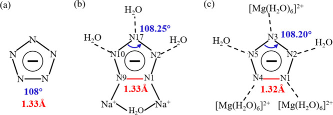
Structure of cyclo-N5–. (a) Minimum energy structure of cyclo-N5–.6 (b, c) cyclo-N5–of Na-cyclo-N5– and Mg-cyclo-N5–, respectively. Longest N–N bonds are shown in red. Maximum N–N–N angles are shown in blue.
Furthermore, the detailed structural characteristics of cyclo-N5– in these two samples were analyzed. In Na-cyclo-N5–, two N ↔ Na ion bonds and three O–H···N HBs are formed surrounding cyclo-N5–, as shown in Figure 2b. N1–N9 is the longest bond in cyclo-N5– (red, 1.33 Å), while the other four N–N bonds are almost equal (black, 1.31 Å). Both N1 and N9 form Na ↔ N ion bonds with Na+. The largest N–N–N angle is located at the para-position of the longest bond (N1–N9), which is 108.25°. In Mg-cyclo-N5–, the five N atoms of cyclo-N5– form five O–H···N HBs, as shown in Figure 2c. N1–N4 is the longest bond in cyclo-N5– (red, 1.32 Å), and both N1 and N4 form HBs with H2O in [Mg(H2O)6]2+. The largest N–N–N angle is located at the para-position of the longest bond (N1–N4), which is 108.20°. The distortion of cyclo-N5– should be related to its stress in the crystal, which will be discussed later (Section 3.4).
3.2. Stability and Electronic Structures
As solid materials, the DOS and the band gap (BG) of an explosive crystal are frequently associated with stability: the narrower the BG is, the easier it is to excite the crystal and the less stable it is.43,44 The total density of states (TDOS) of these two samples was calculated by the PBE functional. As seen in Figure 3, the BGs of Na-cyclo-N5– and Mg-cyclo-N5– are 4.33 and 5.15 eV, respectively. The BG of Mg-cyclo-N5– is larger than that of Na-cyclo-N5–, implying that Mg-cyclo-N5– is more stable, which is in good agreement with the results of lattice energy and binding energy calculations given above.
Figure 3.

TDOS and PDOS calculated by PBE. (a) TDOS and PDOS of Na-cyclo-N5–: TDOS (black solid line); PDOS of Na1-s (red solid line); PDOS of Na1-p (red dotted line); PDOS of N13-s (blue solid line); PDOS of N13-p (blue dotted line); PDOS of O9-s (green solid line); and PDOS of O9-p (green dotted line). (b) TDOS and PDOS of Mg-cyclo-N5–: TDOS (black solid line); PDOS of Mg1-s (red solid line); PDOS of Mg1-p (red dotted line); PDOS of O10-s (blue solid line); and PDOS of O10-p (blue dotted line).
We further analyzed the contribution of metal ions and the surrounding bonding atoms near the valence bands and conduction bands in TDOSs. As shown in Figure 1a, Na1, N13, and O9 were selected as representatives, and their partial density of states (PDOS) values were calculated by PBE for comparative analysis. In Figure 3a, the s-orbital of O9 has a major contribution to the occupied state at −23.59 eV, and the s-orbital and p-orbital of N13 make a dominant contribution to the occupied state at −22.92 eV. The occupied states at −12.25 to −5 eV are mainly contributed by the s-orbital of Na1, the p-orbital of N13, and the p-orbital of O9. Among them, the s-orbital of Na1 and the p-orbital of N13 hybridize to form a coordination bond between cyclo-N5– and Na-cyclo-N5–, sustaining its stability. The s-orbital of Na1 and the p-orbital of O9 hybridize to form a coordination bond between H2O and Na. As shown in Figure 1c, Mg1 and O10 were selected as representatives, and their PDOS values were calculated by PBE for comparative analysis. In Figure 3b, the occupied states between −7.5 and 0 eV are mainly contributed by the s-orbital and p-orbital of Mg1 and the p-orbital of O10. The s-orbital of Mg1 and the p-orbital of O10 are hybridized, resulting in the formation of a coordination bond between Mg and H2O, maintaining the stability of the entire [Mg(H2O)6]2+ structure. In Mg-cyclo-N5–, Mg2+ is not bonded with cyclo-N5–, so no hybridization occurs.
N ↔ Na ion bonds are formed between Na+ and cyclo-N5– to sustain the stability of the crystal in Na-cyclo-N5–, while Mg does not bond with cyclo-N5– in Mg-cyclo-N5–. Logically, Na-cyclo-N5– should be more stable than Mg-cyclo-N5–. However, this conflicts with the result of BG calculations and energy calculations mentioned above. This indicates that the analysis of DOS does not articulate a clear reason why Mg-cyclo-N5– is more stable than Na-cyclo-N5–. For such novel EMs, in addition to the ion bonds, a weak interaction is also a very important factor affecting the stability of the crystal. Therefore, in order to get an in-depth analysis of the stability mechanism for these two samples, we focused on weak interactions.
3.3. Stability and Weak Interactions
3.3.1. Hydrogen Bond
In HEDMs, there are many weak interactions, such as HBs, van der Waals forces, and π-π stacking, in which HBs are one of the important components and have great significance in sustaining the stability of the whole structure. A HB network was considered the main stabilization factor for the two nonmetallic cyclo-N5– energetic salts.31 However, for such cyclo-N5– metal hydrates, systematic studies focusing on HBs have not previously been performed. As demonstrated in Figure 4, two types of HBs are contained in these two samples: O–H···O and O–H···N. In Na-cyclo-N5–, the distribution of HBs is relatively simple: O–H···N [signed as a in Figure 4a] on plane (100), O–H···O [signed as b in Figure 4a] on plane (100), and O–H···N [signed as c in Figure 4a] on plane (001). As shown in Figure 4a, a is located between free H2O (f-H2O) and cyclo-N5–, and its BL is approximately 1.88 Å. b is connected to the f-H2O and the coordinated H2O (c-H2O), whose BL is approximately 1.74 Å. HB c is located between c-H2O and cyclo-N5–, whose BL is approximately 1.94 Å. For cyclo-N5–, based on the abovementioned PDOS analysis, it is known that the Na ↔ N ion bond is a factor in stabilizing cyclo-N5–. Moreover, the HBs a and c also stabilize cyclo-N5– in the crystal. For the whole crystal unit, HBs a and b make the f-H2O stable, and HBs c sustain the stability between the upper and lower layers in the b axis. The details of the HB are listed in Table 4. Na-cyclo-N5– possess the face-to-face crystal packing (layer-by-layer crystal packing). Both the intralayer 2D HB network (composed of HBs a and b) and the HBs between layers (HBs c) maintain the stability of the whole crystal.
Figure 4.

Wireframe models of HBs. (a) HBs in Na-cyclo-N5–. (b) HBs in Mg-cyclo-N5–. (c) O–H···O bonds in Mg-cyclo-N5–. (d) O–H···N bonds in Mg-cyclo-N5–. The a, b, and c directions in the unit cell axis are represented by red, green, and purple lines, respectively. The green dotted line indicates the HBs inside the model.
Table 4. Summary of Hydrogen Bonding Interactions (D–H···R; Å) Operating in the Crystal Structures of Na-Cyclo-N5– and Mg-Cyclo-N5–a.
| donor | H | receptor | D–H (Å) | H···R (Å) | symmetry op. |
|---|---|---|---|---|---|
| Na-cyclo-N5– | |||||
| O1 | H17 | N4 | 0.99 | 1.88 | x, y, z; −1 + x, y, z |
| O1 | H21 | N12 | 0.99 | 1.88 | x, y, z; x, y, z |
| O2 | H18 | N2 | 0.99 | 1.88 | x, y, z; x, 1 + y, z |
| O2 | H22 | N10 | 0.99 | 1.88 | x, y, z; 1 + x, 1 + y, z |
| O3 | H19 | N8 | 0.99 | 1.88 | x, y, z; x, −1 + y, z |
| O3 | H23 | N16 | 0.99 | 1.88 | x, y, 1 + z; −1 + x, −1 + y, z |
| O4 | H20 | N6 | 0.99 | 1.88 | x, y, z; 1 + x, y, z |
| O4 | H24 | N14 | 0.99 | 1.88 | x, y, 1 + z; x, y, z |
| O5 | H1 | O1 | 1.00 | 1.73 | x, y, z; x, y, z |
| O5 | H2 | N20 | 0.98 | 1.94 | x, y, z; x, y, –1 + z |
| O6 | H3 | O2 | 1.00 | 1.73 | x, y, z; x, y, z |
| O6 | H4 | N19 | 0.98 | 1.94 | x, y, z; 1 + x, 1 + y, –1 + z |
| O7 | H5 | O3 | 1.00 | 1.73 | x, y, z; x, y, z |
| O7 | H6 | N18 | 0.98 | 1.94 | x, y, z; −1 + x, −1 + y, z |
| O8 | H7 | O4 | 1.00 | 1.73 | x, y, z; x, y, z |
| O8 | H8 | N17 | 0.98 | 1.94 | x, y, z; x, y, z |
| O9 | H9 | O1 | 1.00 | 1.73 | x, y, z; x, y, z |
| O9 | H10 | N20 | 0.98 | 1.94 | x, y, z; x, y, −1 + z |
| O10 | H11 | O2 | 1.00 | 1.74 | x, y, z; x, y, z |
| O10 | H12 | N19 | 0.98 | 1.94 | x, y, z; 1 + x, 1 + y, −1 + z |
| O11 | H13 | O3 | 1.00 | 1.74 | x, y, z; x, y, −1 + z |
| O11 | H14 | N18 | 0.98 | 1.94 | x, y, z; −1 + x, −1 + y, –1 + z |
| O12 | H15 | O4 | 1.00 | 1.74 | x, y, z; x, y, −1 + z |
| O12 | H16 | N17 | 0.98 | 1.94 | x, y, z; x, y, −1 + z |
| Mg-cyclo-N5– | |||||
| O1 | H2 | N8 | 0.99 | 1.88 | x, y, z; x, y, z |
| O1 | H1 | O3 | 1.00 | 1.67 | x, y, z; ; −1 + x, –1 + y, z |
| O2 | H8 | N5 | 0.99 | 1.81 | x, y, z; 1 + x, y, 1 + z |
| O2 | H9 | N2 | 0.99 | 1.86 | x, y, z; 1 + x, 1 + y, 1 + z |
| O3 | H7 | O10 | 0.99 | 2.40 | x, y, z; 1 + x, 1 + y, 1 + z |
| O3 | H7 | O6 | 0.99 | 1.97 | x, y, z; 1 + x, 1 + y, 1 + z |
| O3 | H6 | O2 | 1.01 | 1.66 | x, y, z; x, y, z |
| O4 | H3 | N4 | 0.99 | 1.85 | x, y, z; x, −1 + y, z |
| O4 | H4 | O7 | 1.00 | 1.74 | x, y, z; 2 + x, 1 + y, 1 + z |
| O5 | H5 | O3 | 1.00 | 1.71 | x, y, z; x, y, z |
| O5 | H10 | N1 | 0.99 | 1.84 | x, y, z; x, y, z |
| O6 | H11 | O8 | 1.00 | 1.67 | x, y, z; 1 + x, 1 + y, z |
| O6 | H12 | N3 | 0.99 | 1.88 | x, y, z; x, y, z |
| O7 | H18 | N10 | 0.99 | 1.81 | x, y, z; −1 + x, y, −1 + z |
| O7 | H19 | N7 | 0.99 | 1.86 | x, y, z; −1 + x, −1 + y, –1 + z |
| O8 | H16 | O7 | 1.01 | 1.66 | x, y, z; x, y, z |
| O8 | H17 | O1 | 0.99 | 1.97 | x, y, z; −1 + x, −1 + y, –1 + z |
| O8 | H17 | O5 | 0.99 | 2.40 | x, y, z; −1 + x, −1 + y, –1 + z |
| O9 | H13 | N9 | 0.99 | 1.85 | x, y, z; x, 1 + y, z |
| O9 | H14 | O2 | 0.99 | 1.74 | x, y, z; −2 + x, −1 + y, –1 + z |
| O10 | H15 | O8 | 1.00 | 1.71 | x, y, z; x, y, z |
| O10 | H20 | N6 | 0.99 | 1.84 | x, y, z; x, y, z |
The distance of H···R and the angle of D–H···R are limited to shorter than 2.5 Å and larger than 120°, respectively.
In Mg-cyclo-N5–, the HBs are more complicated, as shown in Figure 4b–d. In Figure 4b, free H2O 1 and 2 are located between the two [Mg(H2O)6]2+ and far from cyclo-N5–, whose major role is to stabilize the two [Mg(H2O)6]2+. We call them “free H2O away from cyclo-N5–” (fa-H2O). Free H2O 3 and 4 are located between the [Mg(H2O)6]2+ and cyclo-N5–, whose main function is to provide the interaction between cyclo-N5– and [Mg(H2O)6]2+. We call them “free H2O near cyclo-N5–” (fn-H2O). Another class is the six H2O molecules coordinated to Mg2+. We call them ″coordinated H2O″ (c-H2O). All of these three types of water are involved in the formation of HBs. O–H···O bonds in Mg-cyclo-N5– are shown in Figure 4c. There are five O–H···O bonds on each fa-H2O, signed as a′, b′, c′, d′, and e′. The a′ bond is composed of O–H in fa-H2O and O in fn-H2O, and its BL is approximately 1.66 Å. Bonds b′ and c′ are made up of O–H in fa-H2O and O in c-H2O, and their BLs are approximately 2.40 and 1.97 Å, respectively. The d′ and e′ bonds are built up by O–H in c-H2O and O in fa-H2O, and their BLs are approximately 1.707 and 1.67 Å, respectively. There are two O–H···O bonds for each fn-H2O, which are labeled f′ and g′. The O–H in fa-H2O is connected to the O in fn-H2O to form f′, which is equivalent to a′. Bond g′ is between O in fn-H2O and O–H in c-H2O, whose BL is approximately 1.74 Å. Bonds h′ and i′ are the O–H···O bonds for c-H2O, which are equivalent to b′ and e′, respectively. In general, there are more O–H···O bonds in Mg-cyclo-N5– than in Na-cyclo-N5–. These large numbers of HBs come together to form several ring structures, as shown in the small figures on the right side of Figure 4c. The details are shown in Table 5. The ring structures without Mg involvement mainly sustain the stability of [Mg(H2O)6]2+ in the model. The rings with Mg participation keep the free H2O (both fa-H2O and fn-H2O) and [Mg(H2O)6]2+ stable. The other type of HBs in Mg-cyclo-N5–, O–H···N bonds, are shown in Figure 4d. The unit cell contains two cyclo-N5–, which we labeled as (1) (N1, N2, N3, N4, and N5) and (2) (N6, N7, N8, N9, and N10). Every N on each cyclo-N5– forms an O–H···N bond. In other words, 10 O–H···N bonds are formed in total. Among the N atoms, N2, N5, N7, and N10 form O–H···N bonds with fn-H2O, and the others are formed with c-H2O. There are no O–H···N bonds between fa-H2O and cyclo-N5–. Therefore, fn-H2O and c-H2O play an important role in stabilizing cyclo-N5–.
Table 5. Ring Structure Related to O–H···O Bonds in Mg-cyclo-N5– Corresponding to Figure 4c.
| type of rings | type of H2O involved | HB involved (Å) | ||
|---|---|---|---|---|
| no Mg participation | ① O–H···O–H···O–H···O–H···O | two fa-H2O; two c-H2O | b′/h′ | 2.40 |
| e′/i′ | 1.67 | |||
| Mg participation | ② Mg–O–H···O–H···O···H–O–Mg | one fa-H2O; one fn-H2O; two c-H2O and one Mg | a′/f′ | 1.66 |
| d′ | 1.71 | |||
| g′ | 1.74 | |||
| ③ Mg–O···H···O–Mg | one fa-H2O; two c-H2O; and one Mg | b′/h′ | 2.40 | |
| c′ | 1.97 | |||
The number of HBs in Mg-cyclo-N5– is much greater than that in Na-cyclo-N5–: 3 HBs in the primitive cell of Na-cyclo-N5– and 11 HBs in the primitive cell of Mg-cyclo-N5–.24 Different from Na-cyclo-N5– with a 2D HB network, these huge HBs in Mg-cyclo-N5– (not only O–H···O bonds but also O–H···N bonds) form a strong 3D HB network. Moreover, many complex O–H···O ring microstructures are found in the 3D HB network. This means the 3D HB network is superior to the 2D HB network in improving stability. After analyzing the specific structure of the HBs in these two samples, we will further reveal the stability mechanism from the strength of the HB and other weak interactions.
We employed Hirshfeld surfaces to show the weak interactions in these two samples. These surfaces refer to the isosurface of a ratio of the atomic electron density in a particular molecule to the atomic electron density sum of all molecules in the crystal of 0.5. The strength and direction of the interactions in the crystal can be described using the standardized contact distance dnorm (normalized contact distance). dnorm can be obtained according to the following formula 3, where di and de represent the distance from the point on the Hirshfeld surface to the nearest atom in the in-plane and out-of-plane (Å), respectively. In addition, rivdw and revdw represent the van der Waals radii of the corresponding atom in-plane and out-of-plane (Å), respectively.45−48
| 3 |
dnorm enables the identification of regions of particular importance to interactions. That is, a Hirshfeld surface is composed of many points, and each point parameterized as (di, de) can provide information about the related contact distances from it. A relatively low di + de suggests close atom–atom contact. Mapping these (di, de) points and considering their relative frequencies, one can obtain a 2D fingerprint plot. The color mapping distinguishes the intensities and distances of points.49 All the surfaces and fingerprint plots were created using CrystalExplorer 3.1.
To study the stability and weak interactions of these two samples more effectively, we selected different parts for Hirshfeld surface analysis. For Na-cyclo-N5–, we selected three Na+ in the middle of the model, which paralleled to the c-axis, two cyclo-N5– bonded to the center Na+, and four c-H2O molecules surrounding the center Na+ to create the surface, totally 25 atoms. For Mg-cyclo-N5–, we chose one [Mg(H2O)6]2+ structure to create the surface. In Figure 5, we performed three different types of surfaces: Hirshfeld, shape index, and curvedness surfaces. When analyzing the Hirshfeld surfaces, we focused on the red part of the surface, where the interaction between the molecules is the strongest, and the interactions represented by white and blue are progressively weaker than those shown by red. The shape index is a qualitative measure of shape and can be sensitive to very subtle changes in surface shape, particularly in regions where the total curvature (or the curvedness) is very low. The shape index shows a red concave region on the surface around the acceptor atom and a blue region around the donor H atom.50 Curvedness is a function of the root-mean-square curvature of the surface, and maps of curvedness typically show large, green (relatively flat) regions separated by dark blue edges (large positive curvature).
Figure 5.

Hirshfeld surfaces of Na-cyclo-N5– and Mg-cyclo-N5– and with a variety of properties mapped onto the surface. (a, b) Na-cyclo-N5– and Mg-cyclo-N5–, respectively. H···N is shown in a green dotted line. H···O is shown in a red dotted line. The first row: Hirshfeld surfaces, mapped on its natural range (i.e., from minimum to maximum) of −0.668/–0.707 (red) to +1.153/+1.356 a.u.–1 (blue); the second row: shape index, mapped from −1.0 /–0.992 (concave umbilic; red), 0.150/+0.376 (minimal saddle; green), and +0.998/+0.998 (convex umbilic; blue); the third row: curvedness, C, mapped from −3.264/–0.407 (flat; red), −0.981/–0.957 (unit sphere; cyan–green), and +0.448/+0.338 (edge; blue).
In Na-cyclo-N5–, as demonstrated in Figure 5a, the interactions are mainly concentrated on three atoms of N, H, and O, including H···N, H···O, and H···H. The upper and lower layers along the b axis are not directly connected with coordination bonds but form a stable structure by H···N interaction (marked with 1 in Figure 5a), that is, HB c in Figure 4a. Along the c-axis, H···N interactions (marked with 3 in Figure 5a) are formed, that is, HB a in Figure 4a. H···O intermolecular interactions (marked with 2 in Figure 5a) are formed between H in c-H2O and O in f-H2O, that is, HB b in Figure 4a. It can be seen from the shape index diagram that in the H···N interactions (marked with 1′ and 3′ in Figure 5a, corresponding to the preceding 1 and 3), when H is outside the surface, the surface appears red (concave), and when H is located inside the surface, the surface appears blue (convex). This implies that the H atoms in the H···N interactions are donor atoms. Similarly, the donor atoms in the H···O bonds (marked with 2′ in Figure 5a, corresponding to the preceding 2) are also H atoms. Overall, there are two kinds of interactions in Na-cyclo-N5–; one is the electrostatic interaction between cyclo-N5–and H2O, and the other is the intermolecular interaction between c-H2O and f-H2O. The curvature diagram is almost green, indicating that the curvature is relatively small and the surface is relatively flat.
In Mg-cyclo-N5–, as shown in Figure 5b, the type of interaction is similar to that shown in Figure 5a. cyclo-N5– is stabilized by H···N interactions (marked with 1 in Figure 5b), that is, HBs related to cyclo-N5– in Figure 4d. The upper and lower [Mg(H2O)6]2+ ions along the b axis form a stable structure by H···O interactions (marked with 2 in Figure 5b), that is, HBs a′, b′, c′, d′, e′, f′, h′, and i′ in Figure 4c. Two fn-H2O molecules located on the diagonal of the model also formed H···O interactions (marked with 3 in Figure 5b)] with c-H2O, that is, HB g′ in Figure 4c. Similar to Figure 5a, the donor atoms in the H···N (marked with 1′ in Figure 5b, corresponding to the preceding 1) and H···O (marked with 2′ and 3′ in Figure 5b, corresponding to the preceding 2 and 3) are H atoms. There are also two kinds of interactions in Mg-cyclo-N5–; one is the electrostatic interaction between cyclo-N5– and H2O, and the other is the intermolecular interaction among the three types of H2O molecules. Not only is there no bond between cyclo-N5– and Mg2+, but also there is no interaction. The curvature diagram shows the amount of red and yellow areas, indicating that the surface curvature is relatively large. This suggests that a large curvature may contribute to the production of interactions, which in turn increases the ratio of intermolecular/electrostatic interactions in the model and thereby enhances the stability of the crystal. Compared to Na-cyclo-N5–, Mg-cyclo-N5– has more coordination H2O and free H2O, which increases the complexity of its intermolecular and electrostatic interactions.
From the Hirshfeld surface, we can further obtain the 2D fingerprint to analyze the strength of the interaction. When performing 2D fingerprint analysis, two points are generally considered. One is the point of min (di + de), which is located in the bottom-left corner of a fingerprint plot and accompanied by sharp peaks. The smaller the min (di + de), the higher the interaction strength. The other is the frequency at which the point appears: red means that there are many points in the area, and green and blue indicate a successive decreasing number of points. Figure 6 shows the 2D fingerprint plots of these two models. To observe the proportion of each type of interaction directly, Figure 7 shows the percentage chart of contact populations.
Figure 6.

2D fingerprint plots of corresponding to Figure 5. (a) Left: 2D fingerprint plots of Na-cyclo-N5–. Right: 2D fingerprint plots mapped by elements. Bottom right corner: Hirshfeld surfaces corresponding to the interaction. (b) Left: 2D fingerprint plots of Mg-cyclo-N5–. Right: 2D fingerprint plots mapped by elements. Bottom right corner: Hirshfeld surfaces corresponding to the interaction. A···B: A represents an atom inside the surfaces, and B represents an atom outside the surface.
Figure 7.
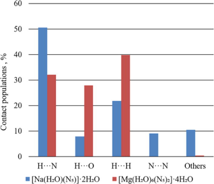
Distribution of individual intermolecular interactions on the basis of Hirshfeld surface analysis of Na-cyclo-N5– and Mg-cyclo-N5–. A···B: include reciprocal contacts.
In Na-cyclo-N5–, as shown in Figure 6a, there are three sharp peaks in the bottom-left corner: H···N (green), H···O (green) and N···H (red). As analysis above, weak interaction H···N and N···H are both O–H···N HBs, and weak interaction H···O is O–H···O HB. Therefore, in Na-cyclo-N5–, HB is the strongest interaction. The min (di + de) of N···H is approximately 1.9 Å, whereas the min (di + de) of H···O is approximately 1.8 Å. Therefore, in Na-cyclo-N5–, the strength of O–H···O is stronger than O–H···N. The red peak of N···H indicates that it possesses a higher frequency. As shown in Figure 7, the proportions of N···H, H···O, and H···H are 50.6, 7.9, and 21.9%, respectively. Meanwhile, in Mg-cyclo-N5–, there are three sharp peaks in the bottom-left corner: H···N (red), H···O (red), and O···H (blue), as shown in Figure 6b. The min (di + de) of N···H is approximately 1.8 Å, whereas the min (di + de) of H···O is approximately 1.7 Å. As a result, the strength of O–H···O is stronger than O–H···N in Mg-cyclo-N5–. Red peaks of N···H and H···O indicate that their frequencies are relatively high. As shown in Figure 7, the proportions of N···H, H···O, and H···H are 32.1, 27.8, and 39.9%, respectively. They also play a role in stability.
According to the results of Hirshfeld surfaces and 2D fingerprint, O–H···O and O–H···N are the strongest interactions in both the samples, which play a major role in maintaining the stability of the crystal. The strength of O–H···O is higher than that of O–H···N. Therefore, O–H···O has a higher contribution to sustaining the stability of the whole crystal. Because the HBs around cyclo-N5– in both samples are all O–H···N, they stabilize cyclo-N5– in the crystal. In Table 4, the distance of H···O and H···N is shorter in Mg-cyclo-N5– than in Na-cyclo-N5–, which indicates that the HBs in Mg-cyclo-N5– may be stronger. This inference is verified here. Comparing the min (di + de) of two samples, the strength of O–H···O and O–H···N in Mg-cyclo-N5– is slightly higher than that in Na-cyclo-N5–. This is another reason why Mg-cyclo-N5– is more stable.
3.3.2. π-π Stacking Interaction
Moreover, because the Hirshfeld surface group we selected above is [Mg(H2O)6]2+ in Mg-cyclo-N5–, N was not selected. Therefore, the interaction force between N···N in Mg-cyclo-N5– was not considered, which we will discuss further below. As shown in the lower left corner of Figure 8a, we selected one cyclo-N5– (N1–N2–N3–N4–N5) to perform the Hirshfeld surface and 2D fingerprint plot. The N···N interaction accounts for 16.4% of interactions, and the other proportion was contributed by the N···H interaction. Therefore, in addition to O–H···N, N···N also plays an important role in sustaining the stability of cyclo-N5– in Mg-cyclo-N5–. As demonstrated in Figure 8b, N···N interactions mean that there are face-to-face π-π stacking interactions in the two parallel cyclo-N5–. The distance between two cyclo-N5– is 3.29 Å, which is shorter than the distance between cyclo-N5– in [Ag(NH3)2]+[Ag3(N5)4]− (3.84 and 3.63 Å).27 Therefore, the strength of π-π stacking interactions in Mg-cyclo-N5– is even stronger than that in [Ag(NH3)2]+[Ag3(N5)4]−. Although there are N···N interactions in Na-cyclo-N5– (Figures 6 and 7), there are no face-to-face π-π stacking interactions between cyclo-N5– according our calculations. When the centroid–centroid distance is less than 3.80 Å, and the angle between the centroid–centroid line and vertical line is less than 20°, face-to-face π-π stacking interactions will exist.51 The centroid–centroid distance in Na-cyclo-N5– is 4.924 Å and the angle between centroid–centroid line and vertical line is approximately 45°. The abovementioned conditions are not satisfied, so there is no face-to-face π-π stacking interaction between two parallel cyclo-N5– in Na-cyclo-N5–. The N···N in Na-cyclo-N5– is just the edge-to-edge weak interaction between two adjacent cyclo-N5– rings.
Figure 8.

N···N interaction in Mg-cyclo-N5–. (a) 2D fingerprint plots of N···N. In the lower left corner is the corresponding Hirshfeld surface. (b) Structure of two cyclo-N5–. The a, b, and c directions in the unit cell axis are represented by red, green, and purple lines, respectively. The blue dotted line indicates the distance between two cyclo-N5–.
To get the scope of weak interaction intuitively, noncovalent interaction analysis was performed by Multiwfn,53 and the results are shown in Figure 9. From the color-filled reduced density gradient (RDG) isosurface,54 we can identify different types of regions by simply examining their colors. The dark blue implies the stronger attractive interaction, which is considered to be hydrogen bonding. The green can be identified as the vdW interaction region, which exhibits that the density electron in this region is low. The red means the strong repulsion. In Figure 9a,b, it can be seen that the elliptical slab between between nitrogen atoms from cyclo-N5– and hydrogen atoms from H2O shows blue color, so we can conclude that there is a HB. From their scatter graphs (Figure 9c,d), it can be found that the HBs in Mg-cyclo-N5– are stronger than those in Na-cyclo-N5–, which is consistent with the Hirshfeld surface analysis in Figure 6. Obviously, the regions at the center of the cyclo-N5– rings correspond to a strong steric interaction because they are filled by red. From both RDG isosurface and scatter graphs, the π-π interaction regions in Mg-cyclo-N5– are significantly larger than those in Na-cyclo-N5–. Although Na-cyclo-N5– is a layer-by-layer crystal packing structure, the interlayer π-π interaction is discontinuous, due to the misalignment of the cyclo-N5– ring between layers by approximately 45°. Just the small-area edge-to-edge π-π interaction between two adjacent cyclo-N5– rings was observed. However, Mg-cyclo-N5– has large areas of face-to-face π-π interactions between two parallel cyclo-N5– rings. Therefore, π-π stacking interactions between two cyclo-N5– also play an important role in sustaining stability for these two samples. Our analysis shows that it is stronger in Mg-cyclo-N5– than that in Na-cyclo-N5–. It is also one reason why Mg-cyclo-N5– is more stable than Na-cyclo-N5–.
Figure 9.

Noncovalent interaction analyses. (a, b) Color-filled reduced density gradient (RDG) isosurface for Na-cyclo-N5– and Mg-cyclo-N5–, respectively. (c, d) Scatter graphs for Na-cyclo-N5– and Mg-cyclo-N5–, respectively. Blue: strong attraction; green: weak interaction; red: strong repulsion.
For these two samples, there are two main noncovalent interactions in the crystals: HB and π-π interaction. According to Figure 9, the more negative the sign(λ2)ρ, the higher the strength of the interaction. It is clear that the strength of HB is much higher than that of π-π interaction. Therefore, HB is the most important factor of the stabilization mechanism. O–H···O is stronger and can stabilize the crystal, while O–H···N is connected with N in cyclo-N5–, so it mainly stabilizes cyclo-N5–. Both 2D and 3D HB networks stabilize the crystal structure. The nature of HB in the crystal is electrostatic interaction (blue), while the nature of π-π interaction is dispersion, and its strength is lower than that of HB. Face-to-face π-π interaction only exists in Mg-cyclo-N5– and mainly stabilizes the cyclo-N5– ring. Other types of π-π interaction contribute to the stability of the crystal.
3.4. Stability and Cyclo-N5–
To further analyze the stability mechanism of cyclo-N5– in the crystal, we calculated the electron localization function (ELF) of the cyclo-N5– plane, as shown in Figure 10. The ELF represents the relative degree of electron localization in the periodic structures.52 According to the definition, 0 ≤ ELF ≤1, the closer the ELF value is to 1, the higher the degree of electron localization (red area); in the area close to 0.5, electrons have the property of free electrons (green area); in the area close to 0, there is almost no electron localization (blue area). In Figure 10a, the electrons around cyclo-N5– are mainly concentrated on the N ↔ Na ion bond and O–H···N. Among them, the red area of N ↔ Na is relatively large, which indicates that the force is relatively strong, and the O–H···N interaction is obviously weaker than that of N ↔ Na. The different bonding modes surrounding cyclo-N5–, ion bond, and HB result in the nonuniform stress of cyclo-N5– in Na-cyclo-N5–. As analyzed in Figure 2b, the distortion of cyclo-N5– is caused by such nonuniform stress. Cyclo-N5– will be more likely to decompose into N2 and N3– upon stimulation. As reported for [M(N5)2(H2O)4]·4H2O (M = Mn, Fe, Co, and Zn), c-H2O binds with M to reduce the M ↔ cyclo-N5– interaction, leading to a less activated cyclo-N5– and higher kinetic barriers for its decomposition.6 It is suggested that the formation of the Metal-N (Na ↔ N) ion bond is not beneficial to the stability of cyclo-N5– when the metal cation (Na+) acts as cyclo-N5– trap. In Figure 10b, the force around cyclo-N5– is relatively uniform, resulting in a lower cyclo-N5– distortion (as shown in Figure 2c and Table 3) and, in turn, increased stability. All five uniformly stressed HBs take advantage of their permanent electrostatic interaction with cyclo-N5– to inhibit decomposition. In Figure 10c,d, the distance between N···H in Mg-cyclo-N5– is approximately 0.44 Å shorter than that in Na-cyclo-N5–. Therefore, the N···H interaction in Mg-cyclo-N5– is stronger, which is consistent with the Hirshfeld and 2D fingerprint analysis.
Figure 10.

Interactions around cyclo-N5–, bond length, and ELF calculated on the cyclo-N5– plane. (a, b) ELF of Na-cyclo-N5– and Mg-cyclo-N5–, respectively (c, d) Interactions around cyclo-N5–: black dotted line indicates the distance of interaction.
In Table 6, the Laplacian bond order (LBO) of cyclo-N5– in the two species was calculated by Multiwfn.53 LBO is adopted to judge the strength of bond covalency, which is based on integrating negative parts of Laplacian of electron density in fuzzy overlap space.55 LBO has a direct correlation with the bond polarity, the bond dissociation energy, and the bond vibrational frequency. In Na-cyclo-N5–, LBOs of N2-N3 and N4-N5 are the smallest, both of which are 1.42. Compared with the other three N–N bonds in the cyclo-N5–, their bond covalency is lower, so their strength is the lowest. This is consistent with the results of the ELF analysis mentioned above. The force on N3 and N5 is the strongest, so cyclo-N5– is easy to break at the position of N2–N3 and N4–N5 to form N2 and N3– under high temperature and high pressure. In Mg-cyclo-N5–, the weakest LBO is N4–N5, 1.45, followed by N2–N3, 1.46. Their bond covalency is stronger than cyclo-N5– in Na-cyclo-N5–. The covalency difference of the five N–N bonds in cyclo-N5– of Mg- cyclo-N5– is smaller than that of Na- cyclo-N5–. Therefore, cyclo-N5– is more stable in Mg-cyclo-N5– than in Na-cyclo-N5–. This further proves that Mg-cyclo-N5– is more stable, consistent with the abovementioned analysis results.
Table 6. Laplacian Bond Order (LBO) of Cyclo-N5– in Na-Cyclo-N5– and Mg-Cyclo-N5– Corresponding to Figure 10c,d, Respectively.
| bond | LBO | |
|---|---|---|
| Na-cyclo-N5– | N1–N2 | 1.50 |
| N1–N4 | 1.50 | |
| N2–N3 | 1.42 | |
| N4–N5 | 1.42 | |
| N3–N5 | 1.52 | |
| Mg-cyclo-N5– | N1–N2 | 1.52 |
| N1–N4 | 1.53 | |
| N2–N3 | 1.46 | |
| N4–N5 | 1.45 | |
| N3–N5 | 1.55 |
4. Conclusions
Stability has always been an important topic in the study of cyclo-N5–-containing HEDMs. In this work, we gained insights into the factors affecting the stability of Na-cyclo-N5– and Mg-cyclo-N5– HEDMs by the first-principles method. Both binding/lattice energy calculations and DOS analysis show that Mg-cyclo-N5– is more stable than Na-cyclo-N5–.
For these two samples, two types of HBs, O–H···O and O–H···N, are the main factors in the stabilization mechanism. The O–H···O is stronger and can stabilize the crystal, while O–H···N is connected with N in cyclo-N5–, so it mainly stabilizes cyclo-N5–.
For the crystal, the intralayer 2D HB network in Na-cyclo-N5– and the 3D HB network in Mg-cyclo-N5– are formed. Many complex O–H···O ring microstructures, the huge number of HBs, and the larger Hirshfeld surface curvature of metal cation groups are found in the 3D HB network. For such reasons, the 3D HB network is considered superior to the 2D HB network.
For cyclo-N5–, in addition to O–H···N HBs, π-π stacking interaction is also an important stabilizing factor. Nonuniform stress caused by different bonding modes results in the distortion of cyclo-N5–. Two N ↔ Na ion bonds and three HBs are formed surrounding cyclo-N5– in Na-cyclo-N5–, while cyclo-N5– in Mg-cyclo-N5– is not bonded with metal ions Mg2+, but five HBs are formed. ELF analysis shows the nonuniform stress on cyclo-N5– in Na-cyclo-N5–. Comparing the two samples, the distortion degree of cyclo-N5– is higher in Na-cyclo-N5–, which may more likely induce cyclo-N5– decomposition. Maintaining the uniform stress of cyclo-N5– is crucial to reduce its distortion.
In summary, our findings not only reveal the stabilization mechanism of two cyclo-N5–-containing metal hydrates, but also enhance the prospects for the design and synthesis of such novel cyclo-N5–-containing HEDMs.
Acknowledgments
This work was supported by NSAF (Grant No. U1730244), the General Program of National Natural Science Foundation of China (Grant No. 21975128 and Grant No. 11972178), and National Natural Science Foundation of China (Grant No. 21903044). We acknowledge the computational support from Beijing Applied Physics and Computational Mathematics (IAPCM).
The authors declare no competing financial interest.
References
- Glukhovtsev M. N.; Jiao H.; Schleyer P. R. Besides N2, What Is the Most Stable Molecule Composed Only of Nitrogen Atoms?. Inorg. Chem. 1996, 35, 7124–7133. 10.1021/ic9606237. [DOI] [PubMed] [Google Scholar]
- Christe K. O. Recent Advances in the Chemistry of N5+, N5– and High-Oxygen Compounds. Propellants Explos. Pyrotech. 2007, 32, 194–204. 10.1002/prep.200700020. [DOI] [Google Scholar]
- Singh R. P.; Verma R. D.; Meshri D. T.; Shreeve J. M. Energetic nitrogen-rich Salts and Ionic Liquids. Angew. Chem., Int. Ed. 2006, 45, 3584–3601. 10.1002/anie.200504236. [DOI] [PubMed] [Google Scholar]
- Wang P.; Xu Y.; Lin Q.; Lu M. Recent advances in the syntheses and properties of polynitrogen pentazolate anion cyclo-N5– and its derivatives. Chem. Soc. Rev. 2018, 47, 7522–7538. 10.1039/C8CS00372F. [DOI] [PubMed] [Google Scholar]
- Hirshberg B.; Gerber R. B.; Krylov A. I. Calculations predict a stable molecular crystal of N8. Inorg. Chem. 2014, 6, 52–56. 10.1038/nchem.1818. [DOI] [PubMed] [Google Scholar]
- Luo J. H.; Chen L. Y.; Nguyen D. N.; Guo D.; An Q.; Cheng M. J. J. Dual Functions of Water in Stabilizing the Metal-Pentazolate Hydrates [M(N5)2(H2O)4]·4H2O (M = Mn, Fe, Co, and Zn) High-Energy Density Materials. J. Phys. Chem. C 2018, 122, 21192–21201. 10.1021/acs.jpcc.8b06671. [DOI] [Google Scholar]
- Bieske E. J. Photodissociation of (N2)+n clusters (2≤n≤7): Branching ratios for formation of N2+ and N4+, and N2+ fragment vibrational excitation. J. Chem. Phys. 1993, 99, 8672–8679. 10.1063/1.465591. [DOI] [Google Scholar]
- Ruchti T.; Speck T.; Connelly J. P.; Bieske E. J.; Linnartz H.; Maier J. P. Rotationally resolved infrared absorption spectrum of N4+. J. Chem. Phys. 1996, 105, 2591–2594. 10.1063/1.472124. [DOI] [Google Scholar]
- Cacace F.; de Petris G.; Troiani A. Experimental Detection of Tetranitrogen. Science 2002, 295, 480–481. 10.1126/science.1067681. [DOI] [PubMed] [Google Scholar]
- Christe K. O.; Wilson W. W.; Sheehy J. A.; Boatz J. A. N5+: A Novel Homoleptic Polynitrogen Ion as a High Energy Density Material. Angew. Chem., Int. Ed. 1999, 38, 2004–2009. . [DOI] [PubMed] [Google Scholar]
- Vij A.; Wilson W. W.; Vij V.; Tham F. S.; Sheehy J. A.; Christe K. O. Polynitrogen Chemistry. Synthesis, Characterization, and Crystal Structure of Surprisingly Stable Fluoroantimonate Salts of N5+. J. Am. Chem. Soc. 2001, 123, 6308–6313. 10.1021/ja010141g. [DOI] [PubMed] [Google Scholar]
- Dixon D. A.; Feller D.; Christe K. O.; Wilson W. W.; Vij A.; Vij V.; Jenkins H. D. B.; Olson R. M.; Gordon M. S. Enthalpies of Formation of Gas Phase N3, N3–, N5+, and N5– from Ab Initio Molecular Orbital Theory, Stability Predictions for N5+N3– and N5+N5–, and Experimental Evidence for the Instability of N5+N3–. J. Am. Chem. Soc. 2004, 126, 834–843. 10.1021/ja0303182. [DOI] [PubMed] [Google Scholar]
- Hirshberg B.; Gerber R. B.; Krylov A. I. Stability and Energetics of Metastable Molecules: Tetraazatetrahedrane (N4), Hexaazabenzene (N6), and Octaazacubane (N8). J. Phys. Chem. 1992, 96, 1173–1178. 10.1021/j100182a029. [DOI] [Google Scholar]
- Hirshberg B.; Gerber R. B. Decomposition mechanisms and dynamics of N6: Bond orders and partial charges along classical trajectories. Chem. Phys. Lett. 2012, 531, 46–51. 10.1016/j.cplett.2012.01.088. [DOI] [Google Scholar]
- Eremets M. I.; Gavriliuk A. G.; Trojan I. A.; Dzivenko D. A.; Boehler R. Single-bonded cubic form of nitrogen. Nat. Mater. 2004, 3, 558–563. 10.1038/nmat1146. [DOI] [PubMed] [Google Scholar]
- Mailhiot C.; Yang L. H.; McMahan A. K. Polymeric nitrogen. Phys. Rev. B 1992, 46, 14419–14435. 10.1103/PhysRevB.46.14419. [DOI] [PubMed] [Google Scholar]
- Mattson W. D.; Sanchez-Portal D.; Chiesa S.; Martin R. M. Prediction of New Phases of Nitrogen at High Pressure from First-Principles Simulations. Phys. Rev. Lett. 2004, 93, 125501 10.1103/PhysRevLett.93.125501. [DOI] [PubMed] [Google Scholar]
- Wang X.; Tian F.; Wang L.; Cui T.; Liu B.; Zou G. Structural stability of polymeric nitrogen: A first-principles investigation. J. Chem. Phys. 2010, 132, 024502 10.1063/1.3290954. [DOI] [PubMed] [Google Scholar]
- Vij A.; Pavlovich J. G.; Wilson W. W.; Vij V.; Christe K. O. Experimental detection of the pentaazacyclopentadienide (pentazolate) anion, cyclo-N5–. Angew. Chem., Int. Ed. 2002, 41, 3051–3054. . [DOI] [PubMed] [Google Scholar]
- Östmark H.; Wallin S.; Brinck T.; Carlqvist P.; Claridge R.; Hedlund E.; Yudina L. Detection of pentazolate anion (cyclo-N5– ) from laser ionization and decomposition of solid p-dimethylaminophenylpentazole. Chem. Phys. Lett. 2003, 379, 539–546. 10.1016/j.cplett.2003.08.081. [DOI] [Google Scholar]
- Bazanov B.; Geiger U.; Carmieli R.; Grinstein D.; Welner S.; Haas Y. Detection of Cyclo-N5– in THF Solution. Angew. Chem., Int. Ed. 2016, 55, 13233–13235. 10.1002/anie.201605400. [DOI] [PubMed] [Google Scholar]
- Zhang C.; Sun C.; Hu B.; Yu C.; Lu M. Synthesis and characterization of the pentazolate anion cyclo-N5– in (N5)6(H3O)3(NH4)4Cl. Science 2017, 355, 374–376. 10.1126/science.aah3840. [DOI] [PubMed] [Google Scholar]
- Christe K. O. Polynitrogen chemistry enters the ring. Science 2017, 355, 351–353. 10.1126/science.aal5057. [DOI] [PubMed] [Google Scholar]
- Zhang C.; Yang C.; Hu B.; Yu C.; Zheng Z.; Sun C. A Symmetric Co(N5)2(H2O)4·4H2O High-Nitrogen Compound Formed by Cobalt(II) Cation Trapping of a Cyclo-N5– Anion. Angew. Chem., Int. Ed. 2017, 56, 4512–4514. 10.1002/anie.201701070. [DOI] [PubMed] [Google Scholar]
- Xu Y.; Wang Q.; Shen C.; Lin Q.; Wang P.; Lu M. A series of energetic metal pentazolate hydrates. Nature 2017, 549, 78–81. 10.1038/nature23662. [DOI] [PubMed] [Google Scholar]
- Xu Y.; Wang P.; Lin Q.; Lu M. A Carbon-free Inorganic-metal Complex Consisting of All-nitrogen Pentazole Anion, Zn(II) Cation and H2O. Dalton Trans. 2017, 46, 14088–14093. 10.1039/C7DT03231E. [DOI] [PubMed] [Google Scholar]
- Xu Y.; Lin Q.; Wang P.; Lu M. Stabilization of the Pentazolate Anion in Three Anhydrous and Metal-Free Energetic Salts (N5–)2DABTT2+, N5-GU+, and N5–Oxahy+. Chem. Asian J. 2018, 13, 924–928. 10.1002/asia.201800187. [DOI] [PubMed] [Google Scholar]
- Xu Y.; Wang P.; Lin Q.; Mei X.; Lu M. Self-assembled energetic 3D metal-organic framework [Na8(N5)8(H2O)3]n based on cyclo-N5–. Dalton Trans. 2018, 47, 1398–1401. 10.1039/C7DT04501H. [DOI] [PubMed] [Google Scholar]
- Sun C.; Zhang C.; Jiang C.; Yang C.; Du Y.; Zhao Y.; Hu B.; Zheng Z.; Christe K. O. Synthesis of AgN5 and its extended 3D energetic framework. Nat. Commun. 2018, 9, 1269. 10.1038/s41467-018-03678-y. [DOI] [PMC free article] [PubMed] [Google Scholar]
- Yang C.; Zhang C.; Zheng Z.; Jiang C.; Luo J.; Du Y.; Hu B.; Sun C.; Christe K. O. Synthesis and Characterization of cyclo-Pentazolate Salts of NH4+, NH3OH+, N2H5+, C(NH2)3+, and N(CH3)4+. J. Am. Chem. Soc. 2018, 140, 16488–16494. 10.1021/jacs.8b05106. [DOI] [PubMed] [Google Scholar]
- Xu Y.; Tian L.; Wang P.; Lin Q.; Lu M. Hydrogen bonding network: stabilization of the pentazolate anion in two nonmetallic energetic salts. Cryst. Growth Des. 2019, 19, 1853–1859. 10.1021/acs.cgd.8b01823. [DOI] [Google Scholar]
- Parr R. G.; Yang W. Density-Functional Theory of Atoms and Molecules. Ann. Nucl. Energy 1989, 16, 611–612. [Google Scholar]
- Zhang L.; Jiang S. L.; Yu Y.; Long Y.; Zhao H. Y.; Peng L. J.; Chen J. Phase Transition in Octahydro-1,3,5,7-tetranitro-1,3,5,7-tetrazocine (HMX) under Static Compression: An Application of the First-Principles Method Specialized for CHNO Solid Explosives. J. Phys. Chem. B 2016, 120, 11510–11522. 10.1021/acs.jpcb.6b08092. [DOI] [PubMed] [Google Scholar]
- Jiang C.; Zhang L.; Sun C.; Zhang C.; Yang C.; Chen J.; Hu B. Response to Comment on “Synthesis and characterization of the pentazolate anion cyclo-N5– in (N5)6(H3O)3(NH4)4Cl”. Science 2018, 359, eaas8953 10.1126/science.aas8953. [DOI] [PubMed] [Google Scholar]
- Zhang L.; Yao C.; Yu Y.; Jiang S.; Sun C.; Chen J. Stabilization of the Dual-Aromatic cyclo-N5– Anion by Acidic Entrapment. J. Phys. Chem. Lett. 2019, 10, 2378–2385. 10.1021/acs.jpclett.9b01047. [DOI] [PubMed] [Google Scholar]
- Methfessel M.; Paxton A. T. High-precision sampling for Brillouin-zone integration in metals. Phys. Rev. B 1989, 40, 3616. 10.1103/PhysRevB.40.3616. [DOI] [PubMed] [Google Scholar]
- Perdew J. P.; Burke K.; Ernzerhof M. Generalized Gradient Approximation Made Simple. Phys. Rev. Lett. 1996, 77, 3865–3868. 10.1103/PhysRevLett.77.3865. [DOI] [PubMed] [Google Scholar]
- Kohn W.; Sham L. J. Self-Consistent Equations Including Exchange and Correlation Effects. J. Phys. Rev. 1965, 140, A1133–A1138. 10.1103/PhysRev.140.A1133. [DOI] [Google Scholar]
- Yao C.; Yang Y.; Yu Y.; Sun C. Q.; Wang X. X.; Li H.; Li H.; Zhang L. How stable and powerful can metal cyclo-pentazolate salts achieve? An answer through theoretical crystal design. Cryst. Growth Des. 2020, 20, 4794–4801. 10.1021/acs.cgd.0c00574. [DOI] [Google Scholar]
- Kresse G.; Joubert D. From ultrasoft pseudopotentials to the projector augmented-wave method. Phys. Rev. B 1999, 59, 1758–1775. 10.1103/PhysRevB.59.1758. [DOI] [Google Scholar]
- Blochl P. E. Projector augmented-wrave method. Phys. Rev. B 1994, 50, 17953–17979. 10.1103/PhysRevB.50.17953. [DOI] [PubMed] [Google Scholar]
- Johnson D. A.Metals and Chemical Change; Royal Society of Chemistry, 2002, 1-2. [Google Scholar]
- Zhang C.; Xue X.; Cao Y.; Zhou J.; Zhang A.; Li H.; Zhou Y.; Xu R.; Gao T. Toward low-sensitive and high-energetic co-crystal II: structural, electronic and energetic features of CL-20 polymorphs and the observed CL-20-based energetic–energetic co-crystals. CrystEngComm 2014, 16, 5905–5916. 10.1039/c4ce00584h. [DOI] [Google Scholar]
- Wu C. J.; Yang L. H.; Fried L. E.; Quenneville J.; Martinez T. J. Electronic structure of solid 1,3,5-triamino-2,4,6-trinitrobenzene under uniaxial compression: Possible role of pressure-induced metallization in energetic materials. Phys. Rev. B 2003, 67, 235101 10.1103/PhysRevB.67.235101. [DOI] [Google Scholar]
- Spackman M. A.; Byrom P. G. A novel definition of a molecule in a crystal. Chem. Phys. Lett. 1997, 267, 215–220. 10.1016/S0009-2614(97)00100-0. [DOI] [Google Scholar]
- Spackman M. A.; Jayatilaka D. Hirshfeld surface analysis. CrystEngComm 2009, 11, 19–32. 10.1039/B818330A. [DOI] [Google Scholar]
- Spackman M. A.; McKinnon J. J. Fingerprinting intermolecular interactions in molecular crystals. CrystEngComm 2002, 4, 378–392. 10.1039/B203191B. [DOI] [Google Scholar]
- McKinnon J. J.; Jayatilaka D.; Spackman M. A. Towards quantitative analysis of intermolecular interactions with Hirshfeld surfaces. Chem. Commun. 2007, 37, 3814–3816. 10.1039/B704980C. [DOI] [PubMed] [Google Scholar]
- McKinnon J. J.; Spackman M. A.; Mitchell A. S. Novel tools for visualizing and exploring intermolecular interactions in molecular crystals. Acta Crystallogr. B 2004, 60, 627–668. 10.1107/S0108768104020300. [DOI] [PubMed] [Google Scholar]
- Seth S. K.; Sarkar D.; Kar T. Use of π–π forces to steer the assembly of chromone derivatives into hydrogen bonded supramolecular layers: crystal structures and Hirshfeld surface analyses. CrystEngComm 2011, 13, 4528–4535. 10.1039/c1ce05037k. [DOI] [Google Scholar]
- Lefebvre C.; Rubez G.; Khartabil H.; Boisson J. C.; Contreras-García J.; Hénon E. Accurately extracting the signature of intermolecular interactions present in the NCl plot of the refuced density gradient versus electron density. Phys. Chem. Chem. Phys. 2017, 19, 17928. 10.1039/C7CP02110K. [DOI] [PubMed] [Google Scholar]
- Becke A. D.; Edgecombe K. E. A simple measure of electron localization in atomic and molecular systems. J. Chem. Phys. 1990, 92, 5397. 10.1063/1.458517. [DOI] [Google Scholar]
- Lu T.; Chen F. Multiwfn: A Multifunctional Wavefunction Analyzer. J. Comput. Chem. 2012, 33, 580–592. 10.1002/jcc.22885. [DOI] [PubMed] [Google Scholar]
- Johnson E. R.; Keinan S.; Mori-Sánchez P.; Contreras-García J.; Cohen A. J.; Yang W. Revealing noncovalent interactions. J. Am. Chem. Soc. 2010, 132, 6498–6506. 10.1021/ja100936w. [DOI] [PMC free article] [PubMed] [Google Scholar]
- Lu T.; Chen F. Bond Order Analysis Based on the Laplacian of Electron Density in Fuzzy Overlap Space. J. Phys. Chem. A 2013, 117, 3100–3108. 10.1021/jp4010345. [DOI] [PubMed] [Google Scholar]