

Abstract
Open reduction and internal fixation (ORIF) is a surgical procedure performed with the objectives of restoring normal alignment and providing stability to broken bone fragments after a fracture. This procedure is increasingly used to treat fractures of the distal end of the radius. Reduction is achieved by the surgeon pulling and manipulating the hand while looking at real-time X-rays, and frequently requires large forces to distract impacted fragments from the proximal bone. This study presents the design and preliminary testing of a multi-degree-of-freedom (DOF) device capable of performing both distraction and reduction of fractured bone fragments using a traction splint mechanism with locking ball joints. A prototype was manufactured, and tests were conducted by a practicing hand surgeon. Both qualitative and quantitative tests using a phantom arm were performed. Quantitative force testing found an 80% reduction in the maximum force required to create needed traction, while qualitative tests with a hand surgeon found the device's ability to reduce and stabilize bone fragments while the hardware is secured to be more intuitive and less obstructive than existing techniques.
1 Introduction
The distal radius is one of the most commonly fractured bones in the human body, with over 640,000 fractures being treated each year in the United States alone [1]. Fractures most often occur during a fall in which a hand is outstretched to brace the body for impact, resulting in both dorsal and radial displacements of the distal end of the radius [2]. While such fractures have often been treated with closed reduction and casting, the number of surgical procedures performed has increased 500% over the past five years [1]. This is likely due to the development of anatomical plates (Fig. 1) that result in better alignment and stabilization of the bones during healing, decreased pain, and a faster return to activities of daily living for the patient. The advent of three-dimensional printing, which enables rapid creation of custom metal structures, will likely further increase the number of ORIF procedures performed annually. These plates are particularly well suited for displaced fractures in which the anatomical alignment of the bones is compromised, such as that seen in Fig. 2. Here, one can see the distal end of the radius angulated into the plane of the page in Fig. 2(a) and to the left in Fig. 2(b). Figure 2(c) depicts a nondisplaced fracture in which traditional closed reduction and immobilization with a splint would be most common. Displaced fractures can be further categorized based on whether they were angulated toward the dorsal or volar side of the wrist, and each type will require a different set of movements and ranges of motion performed by the surgeon to reduce the fracture fragments.
Fig. 1.
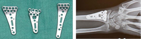
Volar plate. These come in a variety of shapes and sizes to conform to the wrist of the patient and do not need to be removed following surgery.
Fig. 2.

Displaced (a) and (b) versus nondisplaced, (c) fractures
The procedure is composed of four main steps performed by the surgeon: (1) exposure of the fracture site, (2) reduction of the fracture fragments into the correct position, (3) placement of a volar plate to secure the fragments, and (4) closure of the surgical site. One of the most challenging aspects of the procedure, however, occurs during the reduction phase. Due to the combination of dorsal and radial displacements of the distal fragment, this step most often entails pulling and manipulating the hand of the patient to first distract the distal fragment from the residual radius (often requiring large forces) and then aligning the bone fragments while placing the hardware into position, all the while looking at real-time X-rays to ensure each component of the construct is in the correct position.
Current methods for stabilizing the distal fragments often rely on Kirschner wires (K-wires) to temporarily hold bone fragments in place while permanent hardware is screwed into position [3]. These flexible wires are drilled into bone fragments during the operation and then removed following the procedure, and as illustrated in Fig. 3, the surgeon must drill multiple wires into position to secure the bones. K-wires have a variety of limitations that precludes their use in many cases. Due to their relatively thin diameter and flexibility, they can break if insufficient fixation is provided and can sometimes result in movement or shifts of the bone fragments during the surgery. Additionally, because the location of pin insertion is critical to holding the bone in the correct position, the surgeon may have to drill multiple times before the K-wire is inserted correctly. For elderly patients with weaker bones, there is also a high risk of further fracturing the bone when the pins are inserted. Surgeons sometimes find that the use of K-wires is not worth the potential complications and interference in workflow. With regards to traction, it is sometimes held following distraction by hanging a set of weights off the edge of a hand table and connecting these weights to the patient's hand via finger traps. These systems are available commercially and include the Carter Hand Surgery Table System [4]. However, like K-wires, surgeons often find that their use causes too much of an interference in workflow.
Fig. 3.

K-wires are drilled in to stabilize the bone fragments while the volar plate is screwed in position
No device currently exists to aid surgeons in distracting impacted fragments from proximal bone while applying traction, reducing, and temporarily securing the fragments of a distal radius fracture into position.
Accordingly, we present the design and testing of a multi-DOF device that overcomes the limitations of K-wires in stabilizing the bone fragments while simultaneously reducing and applying traction to the fracture site. Similar to splints used by emergency medical personnel to distract and secure traction of femoral fractures, our mechanism uses a ratcheting system to distract the distal end of the radius from the proximal shaft and maintain traction during the procedure. Rotable and locking joints further allow for motion in all DOFs required by the surgeon. Thus, the surgeon is able to manipulate the hand directly, moving the fractured fragments into the correct position, and then holding the alignment by locking the clamps. As a result, the fracture is stabilized in a hands-off state, which enables the surgeon to carefully inspect the alignment, making fine adjustments as needed and ensuring optimal placement of hardware onto the fracture site, potentially leading to fewer complications following distal radius ORIF operations.
2 Design Overview
Primary functional requirements were identified to enhance the current operational procedure of performing open reduction and internal fixation surgery on distal radius fractures. First, the device must be able to dislodge the impacted distal fragment from the proximal bone. The surgeon currently accomplishes this task by taking hold of the patient's hand and pulling on it, which often requires so much force that additional assistance in the form of another surgeon or assistant is required. The device therefore must provide this force with a mechanical advantage that reduces the input force required by the surgeon. Thus, like the mechanism used in traction splints to distract femoral shaft fractures, a ratcheting system was adopted to provide the mechanical advantage needed to distract the impacted fragment from proximal bone and stabilize the fragments once aligned. After the fragment is distracted, tension can be released to enable direct manipulation of the hand by the surgeon and alignment of fragments into the correct anatomical position. Once aligned, tension can be reapplied to aid in the stabilization of fragments during hardware placement.
The second functional requirement involves the device's ability to hold the fragments in place after reduction while minimizing interference with surgeons' current procedure of reducing fracture fragments into alignment. The current practice of reducing fracture fragments to their correct position entails the surgeon manipulating the hand of the patient directly through a variety of degrees of freedom. This motion of the hand results in movement in the internal fractured bones of the wrist. Via this external motion of the hand, the surgeon is able to indirectly move the bone fragments into alignment. From measurements taken during live operations, five degrees-of-freedom were determined necessary to achieve alignment of the distal fragments during surgery. All degrees-of-freedom represent displacements of the hand relative to the forearm. Figure 4 presents the coordinate system utilized and the corresponding magnitudes of the five degrees-of-freedom identified. Note that controlling rotation about the X-axis was deemed unnecessary during the operation.
Fig. 4.

Range of motion requirements: 90 deg dorsal-volar angulation, 60 deg side-to-side rotation, 3 cm forward-backward translation, 2 cm side-to-side translation, 2 cm up-down translation
To meet the high number of degrees-of-freedom required during the operation, coupled ball joints were selected, as each contributes three degrees-of-freedom to the system. After the fragment is distracted and tension released, the surgeon is free to manipulate the hand through all degrees-of-freedom as they would do if the device were not present and is able to do so by grasping the hand directly as opposed to external devices like wires or lead screws. The ball joints remain unlocked until alignment of the fragments is achieved, at which point the surgeon or an assistant can lock the joints, securing the hand and fragments to prevent movement when hardware is secured. This method provides the added benefit of not interacting with the bones of the fracture site directly, as doing so could cause the unwarranted risk of further fracturing the fragments.
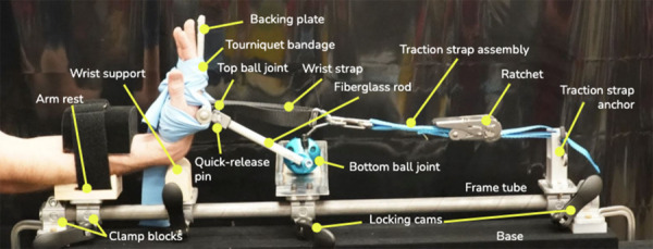
The third functional requirement involves secondary features important to the device's adoption in the clinical setting. Namely, the device must be (1) appropriately transparent to X-rays while the surgeon examines images to install the volar plate and ensure correct alignment, and (2) entirely made of components that are either disposable or sterilizable, as well as body-safe. For greatest adoption, the device must be compatible with existing technologies in the OR, such as bedside arm tables and the C-arm X-ray machine used throughout the operation. In order for the device to be effective on a large range of arm sizes and shapes, many components were designed to be adjustable. The forearm support and wrist support are able to translate and rotate, while the wrist strap can be anchored at three vertical positions and is continuously adjustable along the horizontal axis. The use of a fabric strap and flexible tourniquet bandage allows hands and arms of multiple sizes to be secured to the device. A quick-release pin can be removed to detach the fiberglass rod from the top ball joint so that the surgeon can perform −90 deg-rotation about the y-axis in the process of reduction, as required during some procedures. Figure 5 depicts this design overview.
Fig. 5.

Design overview. The device utilizes a ratchet-based traction strap in combination with two coupled, locking ball joints to enable free manipulation of the hand in multiple degrees-of-freedom. Each component is explained in further detail in the sections that follow.
3 Engineering Design
3.1 Forces and Moments.
To quantify the force a surgeon must exert to distract the distal fragment from the proximal radius, we used a Futek LCM300 load cell to measure a surgeon's maximum pulling force. Each end of the load cell had a steel rod which was used as a gripping surface and was gripped similarly to how the surgeon grips the hand and forearm of the patient when performing distraction. We conducted tests where the surgeon pulled with their maximum force and with a steady-state force for 1 min. As estimated by the hand surgeon, this maximum force was equivalent to the force exerted when performing the distraction step of the operation. Results of the maximum pulling force test revealed a maximum pulling force of 200 N, while the steady-state pulling force was approximately 100 N. We chose to design for a distraction force of 220 N in the x-direction.
Other degrees-of-freedom of the wrist produces reaction forces that are smaller in scale but still significant. These forces were estimated by assuming the reaction force is equivalent to a force couple. Force inputs were taken from the wrist force transformations, as well as estimates for the weight of the arm and additional force for installing the volar plate (Fig. 6, Table 1).
Fig. 6.

Forces and moments in the system
Table 1.
Force and moment inputs in the system
| Force input | Value |
|---|---|
| F traction | 220 N |
| Mwrist (Y angle couple + Z translation couple) | 17 Nm |
| Fsurgeon (acts at Larm/4) | 30 N |
| Warm (acts at Larm/2) | 30 N |
Force and moment balances on the patient's arm and hand were performed to find the moment experienced for the top and bottom ball joint, and the z-direction reaction force at the wrist. The required torques for the top and bottom ball joints were 10 N-m and 27 N-m, respectively. We chose a factor of safety of two, designing for required torques of 20 N-m and 54 N-m.
3.2 Ball Joint Design.
Commercially available ball joints were tested to determine whether they could support the required torque for our system. All ball joints failed at less than 12 N-m of torque applied, motivating the need for a custom ball joint capable of providing a greater holding torque.
The holding torque of a spherical locking ball joint is approximately given by
| (1) |
where T is the maximum holding torque, μ is the coefficient of friction between the ball and the housing, FC is the clamping force, and R is the radius of the ball.
The coefficient of friction was assumed to range from 0.25 to 0.5 for aluminum-on-steel. The clamping force was taken as the maximum force for a 1/4–20 thread-sized cam handle, which represents the maximum force a human would be able to easily exert on the ball joint. The required radius for the larger ball joint at minimum coefficient of friction is about 1 inch (25.4 mm), much larger than anything available off-the-shelf. As a result, we decided to design a custom ball joint with these dimensions (Table 2).
Table 2.
Ball joint sizing
| Maximum μ (0.5) | Minimum μ (0.25) | |
|---|---|---|
| Bottom | ||
| Clamping force (N) | 3892 | 3892 |
| Radius (mm) | 14 | 27 |
| Top | ||
| Clamping force (N) | 3892 | 3892 |
| Radius (mm) | 5 | 11 |
3.3 Rod Sizing.
Fiberglass was chosen for the material of the rod that connects the two ball joints, as it is X-ray transparent. The required diameter of the rod is such that the rod does not yield in bending due to the imposed moment on the end. A factor of safety of 5 was chosen to determine the maximum load the rod will need to support. This was used to calculate the requisite rod diameter. Table 3 displays these calculations. From this analysis, a rod diameter of 0.5 inches (12.7 mm) was chosen.
Table 3.
Sizing fiberglass rod for bending
| Rod moment | 17 Nm |
| Rod diameter | 12.7 m |
| Moment of inertia | 1.28 × 10⁻⁹ m4 |
| Y max | 6.35 mm |
| Stress | 8.45 × 10⁷ Pa |
| Fiberglass strength | 4.12 × 10⁸ Pa |
3.4 Backing Plate Sizing.
The backing plate is splinted to the hand to keep it rigid while being locked in place. The backing plate is roughly modeled as a cantilevered beam with a fixed end and a distributed load from the hand. It is necessary to ensure the backing plate is of sufficient size to prevent any significant deflection under load during the operation. Using Eq. 2, the dimensions of the backing plate were determined such that the resulting deflection was less than 0.1 mm.
| (2) |
where is the maximum deflection, E is Young's modulus, and I is the moment of inertia.
Plate dimensions of 0.25 in. (6.35 mm) by 1 in. (25.4 mm) were determined to be sufficient to obtain a deflection of less than 0.1 mm, as can be seen from the calculations in Table 4.
Table 4.
Sizing backing plate for bending stiffness
| Moment of inertia | 1.19 × 10⁻⁸ m4 |
| Length of splint | 0.1524 m |
| Young's modulus | 6.90 × 10¹⁰ Pa |
| Total load | 70 N |
| End deflection | 3.78 × 10⁻⁵ m |
4 Fabrication of a Prototype
Figure 7 shows the proof-of-concept prototype. The cam handles, clamp blocks, traction belt and ratchet, large ball joint, and arm strap and fasteners were sourced from McMaster-Carr. The small ball joint was sourced from Springfix. See Appendix for part numbers. The tourniquet bandage is standard operating room equipment. The remaining parts were custom fabricated. The arm rest and wrist support were made from pine wood and sanded to the contours of the phantom arm, and in production, such a rest can be made from molded plastic or stainless steel. The frame tube was made from 1-inch (2.54 cm) diameter steel round tube with 0.049-inch (0.124 cm) wall thickness. Although steel is not X-ray transparent, it was chosen to expedite fabrication for early ergonomic testing. Carbon fiber or fiberglass tube of the same size and stiffness can be used to replace it. The wrist strap anchor and backing plate were machined from aluminum by Protolabs. A DIN rail, which was chosen for its versatile mounting options and stiffness, was covered in silicone to create a soft, grippy surface to contact with the back of the hand and was mounted to the backing plate. Finally, the mounting bracket for the large ball joint was made from welded 4130 steel sheets cut on a waterjet.
Fig. 7.
Proof-of-concept prototype
5 Testing
5.1 Quantitative.
To determine the mechanical advantage obtained using the device to distract and hold traction during the operation, and NK-500 Mechanical Analog Push Pull Force Gauge was attached to the ratchet of the device and used to determine the pulling force required to bring the strap to full tension. Multiple tests were performed, and the force required to bring the device to full traction (maximum tension in strap) was recorded at various arm positions and ball joint locations. A value of approximately 45 N was calculated as the average force required to maneuver the ratchet and bring it to full tension. This is an 80% reduction when compared to the force required of the surgeon during a conventional procedure.
5.2 Qualitative.
A practicing hand surgeon had the opportunity to test the device using a phantom arm of latex casing filled with ballistics gel and a 3-D printed fractured distal radius. The surgeon was most pleased with its performance, stating that it was more intuitive and less obstructive than existing techniques, but had concerns regarding the sterilizability of the device as well as the overall length. The issue of sterilizability will be addressed in future iterations of the device, while the length can be shortened by using a shorter strap in conjunction with the ratchet. Figure 8 provides a detailed description of the prototype and the steps a surgeon would take to utilize the device during a surgical procedure.
Fig. 8.

Detailed use case in ORIF surgery of distal radius: (1) patient's forearm is strapped down, (2) wrist support is adjusted and moved into position, (3) ball joint carriage is adjusted and moved into position, (4) traction strap is installed, (5) hand is splinted to backing plate (Not shown: An incision is made on the volar side of the patient's wrist, revealing the fracture site where the hardware is to be installed.) (6) impacted bone fragments are distracted by pulling traction using the device's ratchet mechanism. Once fragments are distracted, tension can be momentarily released. (7) The surgeon manipulates the hand through multiple DOFs in order to reduce the fragments into their correct position. For example, the surgeon may place the wrist in flexion as shown here. Once the fragments are reduced, ball joints can be locked, securing the position of the hand. Traction can be reapplied, and the ball joint carriage locked in place for additional stabilization. (8) Hardware is screwed into place and the incision is closed (not shown).
6 Future Work
While the current prototype is fully functional, a number of developments must be made before entering the OR. First, the custom ball joint must be fabricated to provide sufficient holding force and ensure slippage of the ball joints does not occur during the procedure. A commercially available ball joint can be used for demonstration purposes, but a custom ball joint is optimal. The custom ball joint consists of an aluminum ball inside a steel housing with a spherical seat. The large ball joint is two inches (50.8 mm) in diameter and the small ball joint is one inch (25.4 mm) in diameter. The design is shown in Fig. 9. One side of the housing is free to rotate so that the cutout for the threaded stud can be small. This preliminary design meets force requirements and is easily integrated into the assembly; however, we chose to use the lower holding torque commercially available ball joints for the first prototype in order to expedite completion of an entire assembly that could be preliminarily tested by surgeons. The next iteration will include custom ball joints.
Fig. 9.

Design of custom ball joint
Second, the current prototype uses a metal rod as the base component upon which all other components are attached. This will need to be replaced with a carbon-fiber rod to ensure X-ray transparency. Additionally, methods to improve the sterilizability of the device will be explored. Finally, to allow the setup to be compatible with a larger variety of operating environments, a shorter traction strap should be added to the system. By reducing the length of the strap, the length of the entire system could be reduced significantly. Following the development of this next prototype, user testing with several surgeons may be conducted in a laboratory environment with cadaver bones to compare methods and results. Traditional methods involving manual pulling and K-wires as well as the new approach utilizing the device presented here would be tested and compared. Finally, a clinical trial could be designed and conducted to evaluate the efficacy of the design in the operating environment and compare rates of complications during surgeries performed with and without the use of the device.
7 Conclusion
A prototype of a device to aid surgeons in open-reduction and internal-fixation surgeries of the distal radius was engineered, built, and tested with a phantom. Quantitative tests confirmed a significant reduction in the force required by the surgeon to distract the distal fragment from proximal bone. This was enabled by the use of a ratchet-based multi-DOF design that provides a mechanical advantage to the surgeon and reduces the required distraction force when compared to the current method of pulling on the hand of the patient directly. Qualitative end-user testing with a hand surgeon revealed the device was preferable to current methods of stabilizing bone fragments during reduction, as it does not require additional drilling of wires into bone fragments and may better hold the fractured fragments into position while hardware is secured. Due to the presence of two coupled degree-of-freedom locking ball joints, the surgeon is able to manipulate the hand (and thus indirectly the fractured bone fragments) into the correct position and then secure the entire system by locking the ball joints. As a result, the design presented here possesses the potential to decrease surgical time and improve patient outcomes by allowing easier and more precise alignment of fractured bone fragments during the reduction phase of ORIF surgeries.
Acknowledgment
The team would like to thank the MIT 2.75 staff and sponsors for providing feedback and funding for this project. We would also like to thank MIT Motorsports for allowing us to utilize their shop and resources throughout the fabrication process.
Appendix
Table 5.
Part numbers for purchased components
| Item | Vendor and part number |
|---|---|
| Cam handles | McMaster-Carr 5720K37 |
| Clamp blocks | McMaster-Carr 9578T66 |
| Traction belt and ratchet | McMaster-Carr 31025T721 |
| Large ball joint base | McMaster-Carr 1530N11 |
| Large ball joint locking handle | McMaster-Carr 1530N14 |
| Large ball joint mount | McMaster-Carr 1530N29 |
| Arm strap fasteners | McMaster-Carr 9273K96 |
| Small ball joint | Springfix R3540.MF010 |
References
- [1]. Chung, K. C. , Shauver, M. J. , and Birkmeyer, J. D. , 2009, “ Trends in the United States in the Treatment of Distal Radial Fractures in the Elderly,” J. Bone Jt. Surg., 91(8), pp. 1868–1873. 10.2106/JBJS.H.01297 [DOI] [PMC free article] [PubMed] [Google Scholar]
- [2]. Pogue, D. J. , Viegas, S. F. , Patterson, R. M. , Peterson, P. D. , Jenkins, D. K. , Sweo, T. D. , and Hokanson, J. A. , 1990, “ Effects of Distal Radius Fracture Malunion on Wrist Joint Mechanics,” J. Hand Surg., 15(5), pp. 721–727. 10.1016/0363-5023(90)90143-F [DOI] [PubMed] [Google Scholar]
- [3]. Gibbs, J. , Maclean, A. , and Ricketts, D. , 2006, “ K-Wiring Distal Radial Fractures, an Alternative Technique,” Ann. R. Coll. Surgeons Engl., 88(2), pp. 227–228. 10.1308/rcsann.2006.88.2.227 [DOI] [PMC free article] [PubMed] [Google Scholar]
- [4].Carter Hand Surgery Table System, ( Instrument Specialists, Inc., Boerne, TX, Part Number: CST-2007). [Google Scholar]