

Abstract
Purpose
This study sought to compare the risk of subtrochanteric stress-riser fractures and biomechanical stability of the Femoral Neck System (FNS) versus multiple screw fixation (MSF).
Methods
Eight paired cadaveric femurs were randomly assigned to FNS or MSF. Physiologic load mimicking single leg stance at the subtrochanteric region was applied to the constructs.
Results
No constructs failed in the subtrochanteric region during loading. There was no significant difference in force (P = 0.364) or loading cycles (P = 0.348) between groups.
Conclusion
FNS constructs were not associated with an increased incidence of iatrogenic subtrochanteric fractures or biomechanical stability versus MSF.
Keywords: Biomechanics, Femoral neck system, Femoral neck fractures, Cannulated screws, Stress fracture, Orthopedic trauma
1. Introduction
Nondisplaced and stable femoral neck fractures in elderly patients may be successfully treated by internal fixation. Multiple screw fixation (MSF) and sliding hip screw/blade (SHS) constructs are most commonly used.1 Multiple screw fixation has the advantage of being minimally invasive with less blood loss and shorter operative time, but previous studies have reported considerable failure rates due to weaker biomechanics compared with SHS, especially in vertically oriented fractures.2, 3, 4, 5, 6, 7 Additionally, MSF has been associated with iatrogenic subtrochanteric stress-riser fractures.8, 9, 10, 11 The subtrochanteric region of the femur is an area of great stress concentration, especially along the lateral cortex due to tension forces from the hip abductors in addition to compression forces along the medial cortex from weightbearing.12 Any implant placed in this region can increase stress concentration by creating an area of difference in elastic modulus and can create a stress-riser effect.13 The incidence of subtrochanteric fractures range from 2.4% to 5.7% after multiple screw fixation.8, 9, 10, 11 Previous studies suggested that advanced patient age, triangular-shape configuration with two distal screws,14 screw placement below the level of lesser trochanter,10,11,15 multiple aberrant drill holes at the lateral cortex13 and screws clustered around lesser trochanter11 increase risk for this complication.
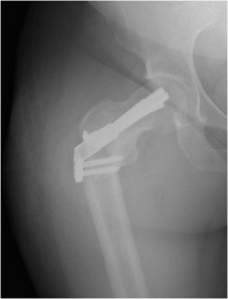
Introduced in 2017, the Femoral Neck System (FNS, DePuy Synthes, West Chester, PA) is a fixed-angle implant made of Ti–Al–N7 that provides both rotational and angular stability for femoral neck fractures. The FNS has been shown to be biomechanically stronger than MSF, having comparable stability to SHS constructs with a minimally invasive surgical technique.16 The FNS has two side-plate options with the one-hole side-plate confirmed to be biomechanically comparable to SHS.16 Given that the single FNS screw-plate ends at, or just distal to, the level of lesser trochanter, we hypothesized that the distal fixation may potentially create a subtrochanteric stress-riser which may create a risk for iatrogenic subtrochanteric fractures. Furthermore, this stress-riser may potentially be exacerbated by bicortical fixation of the distal locking screw in FNS versus the unicortical fixation on the lateral subtrochanteric cortex in MSF. Additionally, the FNS has a larger contact area but fewer holes, which might contribute to different stress concentration in the subtrocanteric region. One case example of this complication is as follows: an 88-year-old female with a stable, minimally displaced intertrochanteric fracture was treated at a referring facility with the FNS (Fig. 1). She did well until one month postoperatively when she fell while standing and sustained a subtrochanteric fracture (Fig. 2). Although the FNS is indicated for transcervical/subcapital fractures rather than intertrochanteric fractures, this case suggests that increased stress concentration distally may contribute to subtrochanteric fracture development. Another example involves a 35-year-old female who sustained a femoral neck fracture after a ground level fall and was appropriately treated with the FNS. She returned with a right subtrochanteric femur fracture 1 month later after a fall from standing (Fig. 3).
Fig. 1.

Original injury AP radiograph.
Fig. 2.

Peri-implant subtrochanteric fracture AP and lateral radiographs.
Fig. 3.
AP radiograph of an additional example of peri-implant subtrochanteric fracture.
Therefore, the primary objective of this study is to compare the risk of iatrogenic subtrochanteric stress-riser fractures caused by the FNS versus MSF in an elderly cadaveric femur model. Furthermore, we also sought to assess the biomechanical load to failure and number of cycles to failure between both constructs. We hypothesized that the FNS would result in a greater-stress riser in the subtrochanteric region than MSF in the intact cadaveric femora, resulting in a lower load to failure and lower number of cycles tolerated.
2. Methods
2.1. Cadaveric specimen preparation
This biomechanical laboratory was study exempt from Institutional Review Board approval. A previous biomechanical study by Zhou et al.13 found that the load to failure at the subtrochanteric region after MSF in an osteoporotic composite femur model was 791 N (Standard Deviation [SD] = 120). At the time of this work, there were no previous biomechanical studies of subtrochanteric fracture after FNS, therefore we referenced a study by Rog et al. (2019) who performed a biomechanical comparison of two and four-hole sliding hip screw fixation to calculate our sample size. Load to failure in their study was 990 N (SD = 124), and a sample size of six specimens in each group was necessary to reach significant differences between groups with an alpha of 0.05 and power of 0.8.17 In our study, eight paired fresh-frozen human cadaveric femurs aged over 60 years were obtained. Radiographs were used to exclude specimens with Kellgren-Lawrence grade 3–4 osteoarthritis,18 neck-shaft angle less than 120° or greater than 135°, and previous hip fracture or implants. Each side of the paired specimens were randomly assigned to FNS or MSF. Femurs were then thawed for 24 h, stripped of any soft tissue, and implanted with either FNS one-hole 130-degree side plate (Fig. 4) or 6.5 mm self-tapping, partially threaded cannulated stainless-steel screws with 16 mm threads (Cannulated Screw System, DePuy Synthes, West Chester, PA). All cannulated screws were placed with washers and in the standard inverted triangle configuration (Fig. 5).
Fig. 4.

Femoral Neck System (FNS) with one-hole side plate. Red-dotted line demonstrates the central axis of femoral neck. Blue-dotted line shows the axis of FNS bolt which is 2 mm lower than the femoral neck axis.
Fig. 5.

Pathway of the three cannulated screws. Red-dotted line demonstrates the horizontal line along midpoint of the lesser trochanter. Yellow, green and blue dotted lines demonstrate the pathways of inferior, anterior and posterior screws respectively.
2.2. Surgical technique - Femoral Neck System
First, a guide wire was inserted under fluoroscopy. On the anteroposterior (AP) fluoroscopic view, the guide wire was placed 2 mm inferior and parallel to the femoral head center axis. On the lateral fluoroscopic view, the guide wire was placed centrally in the femoral neck and head. Once the trajectory of the guidewire was confirmed, the wire was then driven into the subchondral bone, about 10 mm from the apex of femoral head. Using the guidewire, the length of the bolt was then determined with a measuring guide. Following reaming, the bolt and plate were then inserted. Finally, the antirotation-screw and the distal locking screw were inserted. Schematic of the final construct is shown in Fig. 4.
2.3. Surgical technique – multiple cannulated screws
The guide wire for the inferior screw was inserted first. The entry point of the inferior screw was on the lateral cortex of the femur at the level of the midpoint of the lesser trochanter (Fig. 5). This guide wire was aimed closest to the inferior cortex of femoral neck on the AP fluoroscopic view and along the central axis of femoral neck on lateral fluoroscopic view. Next, the anterior-superior wire was inserted parallel to the inferior wire on both the AP and lateral views. The pathway of the anterior-superior wire runs along the anterior-superior cortex of femoral neck. The posterior-superior wire was then inserted last, also parallel to the other wires. On the AP view, the entry point of this wire was slightly inferior to the anterior-superior wire to avoid the piriformis fossa (Fig. 5). Once all the guide wires were placed, the length of the screws was determined with a measuring guide. The screws were then pre-drilled and inserted with washers over the guidewires into the subchondral bone about 5–10 mm from the articular surface.
2.4. Biomechanical testing and statistical analysis
Physiologic load mimicking single leg stance at the subtrochanteric region was applied to the instrumented cadaveric femur. The physiologic load is a combination of joint contact force at the femoral head (body weight) and abductor muscles force at the greater trochanter (71.4% of the joint contact force).12 To create this biomechanic set-up, the femoral shaft was cut perpendicular to the mechnical axis 15 cm distal to the lesser trochanter. The specimen was placed along the mechanical axis. The distal end of the cut femur was potted to the machine using cement. The abductor strap was secured to the proximal femur by a padded clamp placed around the intertrochanteric region (Fig. 6). Fatigue testing of the specimens was performed. Load was applied to the bar to create both joint contact force and hip abductor force. Each specimen was loaded with an initial force of 490% expected bodyweight through the femoral head and abductor force of 350% expected bodyweight. The loading frequence was 2 Hz and the force was increased by 10% every 5,000 cycles until failure occurred. All specimens were cycled to failure. Failure of a specimen was defined by either fracture of the femur or failure of the implant. Gross and radiologic analysis of specimens was performed to assess fracture pattern and for implant breakage. Maximal load to failure in Newtons and number of cycles to failure were recorded. A paired t-test was used to analyze the load to failure data between the two fixation groups. An α-value of 0.05 was used.
Fig. 6.

Biomechanical testing set-up, load applied to the bar to recreate both joint contact force and hip abductor force.
3. Results
Each group had eight cadaveric specimens. The mean ± SD number of cycles tolerated by the MSF group was 61,821 ± 60,711 cycles (range 8,257–170,000 cycles) (Fig. 7). The mean ± SD force tolerated by the MSF group was 1,774 ± 833 N (range 1030–3270 N) (Fig. 8). The mean ± SD cycles tolerated by the FNS group was 39,352 cycles ±33,368 (Range 768–92,707 cycles) (Fig. 7). The mean ± SD force tolerated by the FNS group was 1,476 ± 464 N (960–2220 N) (Fig. 8). There was no significant difference in force (P = 0.364) or loading cycles (P = 0.348) tolerated between groups.
Fig. 7.

Number of cycles tolerated by the MSF vs FNS constructs.
Fig. 8.

Maximum force tolerated by the MSF vs FNS constructs.
3.1. Failure patterns
The MSF constructs tended to fail just distal to the two proximal screws in the inverted triangle. All but one of the FNS constructs failed through the reamer hole for the FNS bolt. Descriptions of the specimen failures are listed in Table 1. All specimens failed by fracture through bone. There was no evidence of implant bending or breakage on any post-failure radiographs. There were no subtrochanteric fractures. Fig. 9 and Fig. 10 show typical failure patterns of both constructs.
Table 1.
Mechanisms of failure of the cadaver pairs.
| Failure Mechanism |
||
|---|---|---|
| Specimen Pairs | MSF Constructs | FNS Constructs |
| 1 | Fracture below the two top screws and above the bottom screw | Specimen broke on the superior side of the plate at the level of the center bolt |
| 2 | Femoral head subsided | Femoral head subsided |
| 3 | Fracture on the shaft at the level of the two top screws | Specimen broke on the superior side of the plate at the level of the center bolt |
| 4 | Fracture below the two top screws and above the bottom screw | Specimen broke on the superior side of the plate at the level of the center bolt |
| 5 | Did not break | Specimen broke on the superior side of the plate at the level of the center bolt |
| 6 | Fracture below the two top screws and above the bottom screw | Specimen broke on the superior side of the plate at the level of the center bolt |
| 7 | Fracture below the two top screws and above the bottom screw | Specimen broke on the superior side of the plate at the level of the center bolt |
| 8 | Fracture below the two top screws and above the bottom screw | Specimen broke on the superior side of the plate at the level of the center bolt |
MSF = Multiple screw fixation.
FNS = Femoral Neck System.
Fig. 9.

Specimen 1, the MSF constructs failed just distal to the proximal two screws.
Fig. 10.

Specimen 6, the FNS construct failed through the reamer hole for the FNS bolt.
4. Discussion
The results of this cadaveric biomechanical study demonstrate no significant difference in force or loading cycles tolerated by either the MSF or the FNS constructs. Furthermore, this study shows that that the MSF constructs tended to fail just distal to the two proximal screws, whereas the FNS constructs tended to failed at the level of the FNS bolt. In all of these failures, the fracture propagated above the lesser trochanter and only through bone, without evidence of implant bending or breakage as determined by radiographs. None of the specimens failed in the subtrochanteric region. Therefore, the results of this study do not support our hypothesis that the FNS would result in a greater risk for iatrogenic subtrochanteric fractures, reduced load to failure, and reduced number of cycles tolerated as compared to MSF. It is important to note that our study did not directly measure stress concentration at the subtrochanteric region, but sought assess this by examining the mechanisms of failure of these constructs. Furthermore, as all but one FNS constructs failed identically at the lateral cortex where the bolt was inserted, our results suggest that this area may potentially be more vulnerable to iatrogenic fracture than the subtrochanteric region. We suspect this is due to weaking of the lateral cortex due to the large diameter reaming required for insertion of the center bolt.
Our findings of no significant difference between the FNS and MSF constructs with regard to maximum number of cycles tolerated are in contrast to the findings presented in Stoffel et al.,16 who demonstrated that the FNS constructs tolerated significantly more cycles until failure than the MSF constructs. This is likely due to our use of an intact femoral neck model, whereas Stoffel et al. created vertically unstable fractures in their femoral neck model.16 The rationale of leaving the femoral neck intact was to specifically examine the risk of subtrochanteric stress fractures instead of construct stability. This also more closely mimics a “healed” femoral neck fracture. Furthermore, the use of a “healed” femoral neck fracture model likely results in the lack of significant difference in maximal load to failure and number of cycles tolerated between the FNS and MSF groups. In the presence of a fracture, the implants fail via direct breakage or by loss of fixation purchase in the bone. However, in our study, because the femoral neck cortex was intact, failures occurred as new fractures in the regions of the highest stress concentration or disruption of cortical integrity.15
Previous biomechanical and clinical studies have demonstrated that screw placement in the MSF construct is critical in avoiding iatrogenic subtrochanteric fractures.11,14 In our study, the entry point for the most inferior screw of the MSF construct was at the level of the middle of the lesser trochanter, which is considered the ideal starting point.15 Sensoz et al.15 have shown in a mathematical model that inferior screw placement distal to the lesser trochanter results the greatest von Mises stresses, suggesting a greater risk for iatrogenic subtrochanteric fractures. Additionally, Oakey et al. have shown that the apex-distal, or inverted triangle, screw configuration withstood a greater load until subtrochanteric fracture than the apex-proximal configuration (mean 11,330 N vs. 7795 N, P = 0.01).
To date, there are no clinical studies reporting iatrogenic subtrochanteric fractures in patients treated with the FNS.19, 20, 21 In a retrospective cohort study, Hu et al. show that the FNS was associated with significantly less femoral neck shortening versus MSF (10.0% versus 37.5%, p = 0.036).19 Nibe et al. retrospectively compared the FNS to multiple other femoral neck fixation constructs, including MSF and SHS, and found that the FNS was associated with lower reoperation rates (0% versus 22%, P = 0.023). Yang et al. did not identify any significant differences in time to union, Harris hip scores, or shortening between their FNS cohort and MSF cohort.21 Although the results from these early retrospective studies are promising, future prospective, randomized studies with a larger number of patients are necessary to better elucidate the advantage of the FNS over MSF, especially with regards to vertically unstable femoral neck fractures.
4.1. Limitations
One major limitation of this study is its in vitro nature, as the loading of the femur at the head and the greater trochanter does not represent all the possible forces that can occur during physiological weightbearing. However, we believe that our biomechanical testing configuration allows for simulation of the two major forces of the proximal femur, which are compressive forces from loading of the femoral head and tension forces from hip abductors. Another limitation of this study is the use of multiple freeze and thaw cycles, as instrumentation and biomechanical testing were performed at separate facilities. This potentially could affect the bone/instrumentation interface. Additionally, we used an unfractured femoral neck model. The purpose of leaving the femoral neck intact was to specifically examine the risk of subtrochanteric stress fractures instead of construct stability. This also more closely represents a “healed” femoral neck fracture model. Thus, our findings may not represent subtrochanteric fractures that occur in the more acute postoperative setting, where the construct biomechanics differ due to the presence of the femoral neck fracture line. Previous case series have demonstrated iatrogenic subtrochanteric fractures to occur both within several days postoperatively to several weeks postoperatively.8, 9, 10, 11
5. Conclusion
The primary finding of this study is that the FNS construct was not associated with an increased incidence of iatrogenic subtrochanteric fractures. Additionally, there was no significant difference in the number of cycles or maximum force tolerated between both constructs in the intact proximal femur model used in this study. Furthermore, we demonstrate that failure occurs primarily at the lateral proximal femoral cortex between the superior and inferior screws in the MSF construct or at the level of the center bolt for the FNS construct.
Funding
This study was funded by a grant from DePuy Synthes (West Chester, PA) under Grant ID: 352937.
Acknowledgements
None.
Biographies
Erik Hasenboehler, MD is a paid consultant for DePuy Synthes Trauma. He receives grant support as well as a grant for a research fellow from DePuy Synthes Trauma. He is also a paid lecturer and faculty for AO North America Trauma and has investment/ownership in OsteoCentric Technologies.
Babar Shafiq, MD, MSPT is a consultant for Depuy Synthes and Bone Foam. The rest of the authors have no financial disclosures.
References
- 1.Brox W.T., Roberts K.C., Taksali S., et al. The American academy of orthopaedic surgeons evidence-based guideline on management of hip fractures in the elderly. J Bone Joint Surg Am. 2015;97:1196–1199. doi: 10.2106/JBJS.O.00229. [DOI] [PMC free article] [PubMed] [Google Scholar]
- 2.Lee Y., Chen S., Tsuang Y., et al. Internal fixation of undisplaced femoral neck fractures in the elderly: a retrospective comparison of fixation methods. J Trauma Inj Infect Crit Care. 2008;64:155–162. doi: 10.1097/TA.0b013e31802c821c. [DOI] [PubMed] [Google Scholar]
- 3.Siavashi B., Aalirezaei A., Moosavi M., et al. A comparative study between multiple cannulated screws and dynamic hip screw for fixation of femoral neck fracture in adults. Int Orthop. 2015;39:2069–2071. doi: 10.1007/s00264-015-2881-9. [DOI] [PubMed] [Google Scholar]
- 4.Baitner A.C., Maurer S.G., Hickey D.G., et al. Vertical shear fractures of the femoral neck: a biomechanical study. Clin Orthop Relat Res. 1999:300–305. [PubMed] [Google Scholar]
- 5.Aminian A., Gao F., Fedoriw W.W., et al. Vertically oriented femoral neck fractures: mechanical analysis of four fixation techniques. J Orthop Trauma. 2007;21:544–548. doi: 10.1097/BOT.0b013e31814b822e. [DOI] [PubMed] [Google Scholar]
- 6.Deneka D.A., Simonian P.T., Stankewich C.J., et al. Biomechanical comparison of internal fixation techniques for the treatment of unstable basicervical femoral neck fractures. J Orthop Trauma. 1997;11:337–343. doi: 10.1097/00005131-199707000-00007. [DOI] [PubMed] [Google Scholar]
- 7.Bonnaire F.A., Weber A.T. Analysis of fracture gap changes, dynamic and static stability of different osteosynthetic procedures in the femoral neck. Injury. 2002;33 doi: 10.1016/s0020-1383(02)00328-5. SC24; SC32. [DOI] [PubMed] [Google Scholar]
- 8.Karr R.K., Schwab J.P. Subtrochanteric fracture as a complication of proximal femoral pinning. Clin Orthop Relat Res. 1985;194:214–217. [PubMed] [Google Scholar]
- 9.Jansen H., Frey S.P., Meffert R.H. Subtrochanteric fracture: a rare but severe complication after screw fixation of femoral neck fractures in the elderly. Acta Orthop Belg. 2010;76:778–784. [PubMed] [Google Scholar]
- 10.Howard C.B., Davies R.M. Subtrochanteric fracture after garden screw fixation of subcapital fractures. J BONE JT SURG SER B. 1982;64:565–567. doi: 10.1302/0301-620X.64B5.7142262. [DOI] [PubMed] [Google Scholar]
- 11.Kloen P., Rubel I.F., Lyden J.P., et al. Subtrochanteric fracture after cannulated screw fixation of femoral neck fractures: a report of four cases. J Orthop Trauma. 2003;17:225–229. doi: 10.1097/00005131-200303000-00013. [DOI] [PubMed] [Google Scholar]
- 12.Tsai A.G., Reich M.S., Bensusan J., et al. A fatigue loading model for investigation of iatrogenic subtrochanteric fractures of the femur. Clin Biomech. 2013;28:981–987. doi: 10.1016/j.clinbiomech.2013.09.009. [DOI] [PubMed] [Google Scholar]
- 13.Zhou S., Jung S., Hwang J. Mechanical analysis of femoral stress-riser fractures. Clin Biomech. 2019;63:10–15. doi: 10.1016/j.clinbiomech.2019.02.004. [DOI] [PubMed] [Google Scholar]
- 14.Oakey J.W., Stover M.D., Summers H.D., et al. Does screw configuration affect subtrochanteric fracture after femoral neck fixation? Clin Orthop Relat Res. 2006:302–306. doi: 10.1097/01.blo.0000188557.65387.fc. [DOI] [PubMed] [Google Scholar]
- 15.Sensoz E., Özkal F.M., Acar V., et al. Finite element analysis of the impact of screw insertion distal to the trochanter minor on the risk of iatrogenic subtrochanteric fracture. Proc Inst Mech Eng H. 2018;232:807–818. doi: 10.1177/0954411918789963. [DOI] [PubMed] [Google Scholar]
- 16.Stoffel K., Zderic I., Gras F., et al. Biomechanical evaluation of the femoral neck system in unstable pauwels III femoral neck fractures: a comparison with the dynamic hip screw and cannulated screws. J Orthop Trauma. 2017;31:131–137. doi: 10.1097/BOT.0000000000000739. [DOI] [PubMed] [Google Scholar]
- 17.Rog D., Grigsby P., Hill Z., et al. A biomechanical comparison of the two-and four-hole side-plate dynamic hip screw in an osteoporotic composite femur model. J Orthop Surg. 2017;25 doi: 10.1177/2309499017717199. [DOI] [PubMed] [Google Scholar]
- 18.Kellgren J.H., Lawrence J.S. Radiological assessment of osteo-arthrosis. Ann Rheum Dis. 1957;16:494–502. doi: 10.1136/ard.16.4.494. [DOI] [PMC free article] [PubMed] [Google Scholar]
- 19.Hu H., Cheng J., Feng M., et al. Clinical outcome of femoral neck system versus cannulated compression screws for fixation of femoral neck fracture in younger patients. J Orthop Surg Res. 2021;16:370. doi: 10.1186/s13018-021-02517-z. [DOI] [PMC free article] [PubMed] [Google Scholar]
- 20.Nibe Y., Matsumura T., Takahashi T., et al. A comparison between the femoral neck system and other implants for elderly patients with femoral neck fracture: a preliminary report of a newly developed implant. J Orthop Sci. 20212021 doi: 10.1016/j.jos.2021.04.016. https://pubmed.ncbi.nlm.nih.gov/34090779/ In press. [DOI] [PubMed] [Google Scholar]
- 21.Yang Y., Ma T., Zhang X., et al. Short-term effectiveness of femoral neck system in the treatment of femoral neck fracture. Zhongguo Xiu Fu Chong Jian Wai Ke Za Zhi. 2021;35:539–543. doi: 10.7507/1002-1892.202012097. [DOI] [PMC free article] [PubMed] [Google Scholar]