This ovine interbody fusion study compared load-induced strain amplitudes, bone mineralization, and fusion outcomes for different diameter struts in a truss-based spinal implant. Truss devices with smaller diameter struts demonstrated faster fusion consolidation, greater mineralized bone, and less fibrous/chondral tissue than truss devices with larger diameter struts.
Keywords: disc degeneration, interbody fusion cage, mechanobiology, osseointegration, ovine, truss
Study Design.
Finite element analysis (FEA) and in vivo ovine spinal interbody fusion study.
Objective.
To determine comparative load-induced strain amplitudes, bone mineralization and fusion outcomes associated with different diameter struts in a truss-based interbody fusion device.
Summary of Background Data.
Additive manufacturing technology has been employed to develop implants that actively participate in the fusion process. The truss device enables the optimal transfer of compressive and tensile stresses via the struts. Mechanobiologic principles postulate that strut diameter can be regulated to allow different magnitudes of strain distribution within the struts which may affect fusion rates.
Methods.
Modeling of strain distributions as a function of strut diameter (0.75, 1.0, 1.25, and 1.5 mm) employed FEA that simulated physiologic loading conditions. A confirmatory in vivo ovine lumbar spinal interbody fusion study compared fusion scores and bone histomorphometric variables for cages with 0.75 and 1.5 mm strut diameters. Outcomes were compared at 3-, 6-, and 12-month follow-up intervals.
Results.
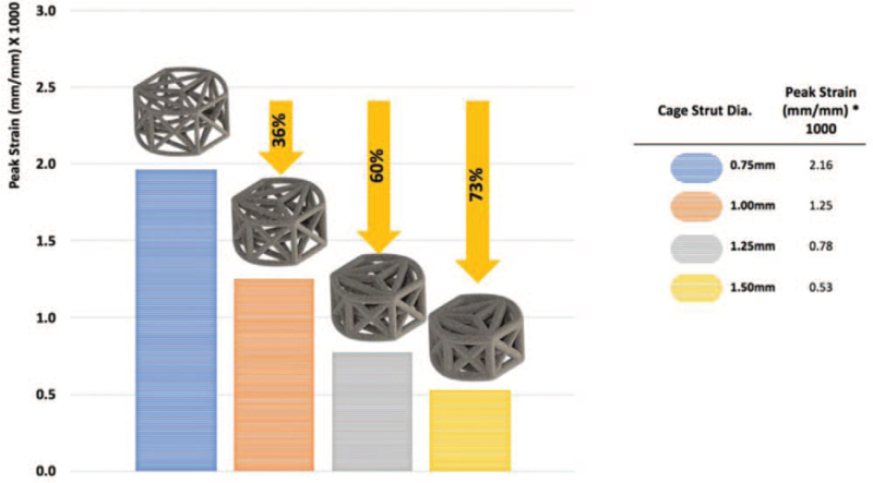
FEA showed an inverse association between strut diameter and peak strain amplitude. Cages with 1.0, 1.25, and 1.5 mm struts had peak strain values that were 36%, 60%, and 73% lower than the 0.75 mm strut strain value. In vivo results showed the mean fusion score for the 0.75 mm diameter strut cage was significantly greater by 3-months versus the 1.5 mm strut cage, and remained significantly higher at each subsequent interval (P < 0.001 for all comparisons). Fusion rates were 95%, 100%, and 100% (0.75 mm) and 72.7%, 86.4%, and 95.8% (1.5 mm) at 3, 6, and 12 months. Thinner struts had greater mineralized bone tissue and less fibrous/chondral tissue than the thicker struts at each follow-up.
Conclusion.
Validating FEA estimates, cages with smaller diameter struts exhibited more rapid fusion consolidation and more aggressive osseointegration compared with cages with larger diameters struts.
Level of Evidence: 4
Instrumented fusion of the anterior column of the lumbar spine is one of several surgical interventions used to manage chronically severe low back and/or leg symptoms associated with degenerative spondylosis.1–3 This procedure involves the operative implantation of an interbody fusion device (or cage) to provide immediate stability across the joint complex, and to offer neural decompression with symptom relief via re-establishment of intervertebral disc height.4 Bone graft is traditionally packed within the confines of the cage to promote osseointegration.5,6
Originally conceived as inert spacers and necessary repositories of bone graft, interbody fusion devices have evolved both structurally and architecturally. Adopting fundamental mechanobiologic principles,7,8 current implant engineering methods employing additive manufacturing techniques can generate, via 3D-printing, advanced lattice structures, such as the micro-truss. This advanced structural design combines biomimetic architectural features with osseo-stimulatory surface modifications to modulate the bone healing and fusion consolidation process. By optimizing strain transfer across the implant, a favorable local mechanical environment can be established to accelerate and guide the bone mineralization process necessary to achieve a mechanically-solid endplate-to endplate arthrodesis.9,10
In theory, the diameters of the struts in a truss lattice can be regulated to allow different magnitudes of strain distribution within the struts and across the joint space,11 which may, in turn, affect fusion rates. The purpose of this study was to compare bone formation and fusion status for truss-based cages with varying strut diameters that differentially distribute strain within the cage.
MATERIALS AND METHODS
The primary objective of this study was to determine comparative bone mineralization and fusion consolidation outcomes associated with struts of different diameters in a truss-based interbody fusion device. Modeling of differential strain distributions as a function of strut diameter employed an ovine finite element analysis (FEA)12 coupled with a confirmatory in vivo ovine spinal interbody fusion study.13 The titanium interbody fusion devices that were investigated in this study (4WEB Medical Inc.; Frisco, TX) were manufactured using additive, 3D-printing technology, to produce a network of intersecting strut-based truss units.
Ovine Finite Element Analysis
FEA modeling was used to simulate the mechanical response as differential strain amplitude distributions for truss cages with different strut diameters under anatomical loading. Ovine FEA of intact L2–L3 sheep lumbar spine model was used.12 The intact spine model included vertebral bone, soft tissue, intervertebral disc, ligaments, posterior facet joints, and other anatomical components.
To simulate placement of the truss cage between the vertebral bodies, the FEA model was modified by partial removal of the intervertebral disc and preparation of the endplate prior to insertion of the implant. The implant was fixed to the adjacent endplate bone at the contact interface. Mechanical properties of the implant were assigned, and the instrumented spine was subjected to anatomical loading. The inferior surface of the lower vertebrae (L3) was fixed in all degrees of freedom and a compression load of 100 N followed by bending moment of 3.4 Nm were applied at the superior surface of L3 segment.12 The process was performed iteratively for truss cages with strut diameters of 0.75-, 1.0-, 1.25-, and 1.5-mm and the peak strain across the cage and the strain distribution were compared.
Surgical Methods
Surgery was completed under an Institutional Animal Care and Use Committee-approved protocol. A left lateral retroperitoneal approach was used and discectomy was performed at L2–L3 and L4–L5 in 18 sheep. Cages were filled with autograft obtained from the iliac crest. Truss implants with two different strut diameters, 0.75 and 1.5 mm, were placed in each animal. Assignments ensured that both cage types were tested in equal numbers at both levels for all time points. Animals were sacrificed at 3, 6, and 12 months (six implants of each type/time point). Spinal segments (L1–L6) were harvested for radiographic, histopathologic, and histomorphometric analysis.
Microradiographic Analysis and Fusion Scoring
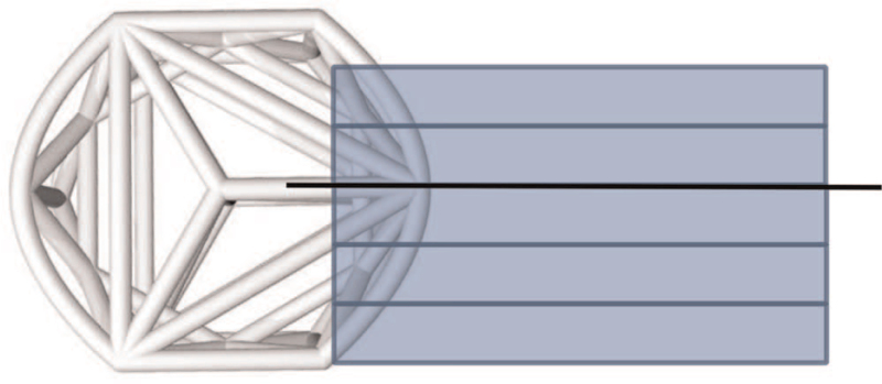
Specimens were fixed in 10% neutral buffered formalin and cut into 4-mm slabs using an EXAKT cutting system (EXAKT Technologies, Inc., Oklahoma City, OK), ensuring that the center strut was retained in one of the slabs (Figure 1). Cutting planes (coronal or oblique to coronal plane) were determined based on device orientation within the operated level and all slabs were cut parallel to one another. At least three microradiographs (FAXITRON Bioptics, LLC, Tucson, AZ) were taken per implant and each slab that contained a complete implant cross-section was used for radiographic scoring.
Figure 1.
Pictorial illustrating the approximate location for the microradiographic and histologic sections. The rectangles depict the approximate location of the microradiographic sections. The line drawn through the center strut shows the approximate histology plane of section.
Two fusion assessments were performed on each microradiograph: one utilized a semi-quantitative (0–3 scale) scoring system (Table 1) and the other used a binary (i.e., yes or no fusion) method in which fusion was defined as a score of 2 or 3.
TABLE 1.
Semiquantitative Microradiographic Fusion and Bone Fill Scoring
| Fusion Criteria | Score | Bone Fill Criteria | Score |
| Fused. Cage filled with bridging trabecular bone | 3 | >50% | 4 |
| Fused. Bridging bone with minimal lucency (<5 mm) in fusion area | 2 | 26–50% | 3 |
| Not fused. Lucency (>5 mm) in fusion area | 1 | 11–25% | 2 |
| Not fused: no bone present | 0 | 1–10% | 1 |
| None | 0 |
Bone fill in the cage for each microradiograph was performed using a semi-quantitative scale (0–4) (Table 1). Bone was identified as radio-dense material having an obvious trabecular structure similar to the appearance of surrounding vertebral cancellous bone.
Histologic Methods and Histomorphometric Analysis
A single slab containing the center strut was embedded in methyl methacrylate (Figure 1). Selection of the center portion for histology assured an in-depth microscopic assessment of fusion at the same central plane through the devices for all specimens irrespective of cage orientation. Central selection additionally enabled visualization of the internal portion of the web structure most susceptible to stress shielding. Sections were stained with Toluidine blue/Paragon.
Two histomorphometric analyses were performed. The first quantitative histomorphometric analysis was completed on the center section within and outside of the cage. The region of interest analyzed was set to a standard area encompassing the internal portion of the implant and 1.5 mm beyond the implant edge in all directions. Imaging used an Olympus BX40 microscope and a combination of transmitted and reflected light to provide the best differentiation possible between the implant and surrounding bone and soft tissues. Images were captured at 10× using a MicroPublisher 3.3 RTV CMOS camera (QImaging, Surrey, BC, Canada). To obtain a composite image of the entire defect region, a series of high-resolution images (2048 × 1536 pixels/field) were taken in sequential fields spanning the region of interest and tiled into a single high-resolution image. Images were analyzed using Image Pro Plus Version 7.0 (MediaCybernetics, Bethesda, MD).
The area of implant, calcified bone, bone marrow, and fibrous/chondral tissue within the region of interest were measured based on color differentiation of the differently-stained tissues. Accuracy of the color differentiation was checked microscopically, and color thresholding adjusted as needed. Percent bone, bone marrow, and fibrous tissue/chondral tissue were calculated as a function of the total region of interest area.
The second quantitative histomorphometric analysis was performed to assess bone ongrowth. Perimeters of the implant surface (inner and outer) with direct calcified bone contact were manually measured to produce a total implant perimeter length. The percent calcified bone ongrowth was calculated as a function of total implant perimeter length.
Statistical Analysis
Mean microradiograph fusion and bone scores (±standard deviation) were calculated. Two-way analysis of variance (ANOVA) with a Benjamini–Hochberg correction for multiple comparisons was used. Means and standard deviations were also calculated for histomorphometric data and differences between groups were determined by one-way ANOVA.
RESULTS
All animals survived the duration of the study period and no adverse clinical effects related to the device implantation were observed.
Finite Element Analysis Estimates
Using FEA to simulate compressive-bending loads, we observed an inverse linear association between cage strut diameter and peak strain as observed in Figure 2. The 0.75 mm diameter construct demonstrated a four-fold higher peak strain in the struts as compared with the cage with 1.5 mm diameter struts (Figure 2). Peak strain values for strut diameters of 1.0 and 1.25 mm were intermediary between those observed for the thickest and the thinnest diameter struts.
Figure 2.
Average peak strain values under simulated compressive loading as a function of strut diameter by FEA. FEA indicates finite element analysis.
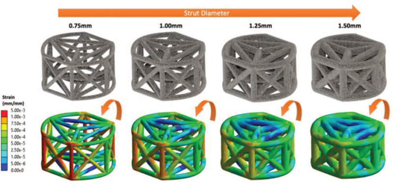
Figure 3 illustrates the distribution of strain amplitudes throughout the struts of the entire truss system as a function of strut diameter. Color mapping highlights higher strains across the entire strut complex for smaller diameter struts compared with larger diameter struts (Figure 3). Following simulated compressive bending, the highest strains were located on the wall opposing the lateral load. Overall, three-dimensional multiplanar stress distribution throughout the entire implant was observed.
Figure 3.
Color mapping illustrating the strain distributions as a function of strut diameter by FEA. FEA indicates finite element analysis.
Microradiographic Evaluation
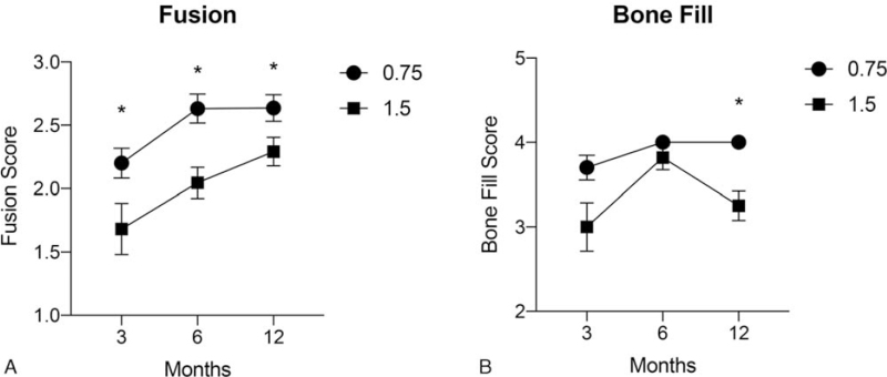
There was a significant increase in mean fusion scores for both diameter strut cages over time (P < 0.001) (Figure 4A). However, the mean fusion score associated with the 0.75 mm diameter strut cage was significantly greater by the initial 3-month interval compared with the 1.5 mm strut cage, and remained significantly higher at each subsequent follow-up interval (P < 0.001 for all comparisons) (Figure 4A). The mean fusion scores were 2.2 ± 0.5, 2.6 ± 0.5, and 2.6 ± 0.5 for the thinner diameter and 1.7 ± 0.9, 2.0 ± 0.6, and 2.3 ± 0.6 for the thicker diameter strut cages at 3, 6, and 12 months, respectively.
Figure 4.
Mean (±SD) semiquantitative fusion scores (A) and bone fill scores (B) at each postoperative follow-up interval for 0.75 and 1.5 mm diameter strut cages. Fusion scores were significantly (∗P < 0.001) greater at all intervals for the 0.75 mm diameter strut cage compared with the 1.5 mm cage. The 0.75 mm strut device also showed a significantly (∗P < 0.001) higher average bone fill score at 12 months, postoperatively.
Similarly, the binary fusion rate for the 0.75 mm diameter strut cage was 95%, 100%, and 100% at 3, 6, and 12 months, respectively. The corresponding fusion rate for the 1.5 mm cage was 72.7%, 86.4%, and 95.8% at the same follow-up intervals.
The comparative mean bone fill scores are provided in Figure 4B. The average fill score for the 0.75 mm diameter strut cage was significantly greater than the 1.5 mm cage only at the 12-month follow-up interval (P < 0.001).
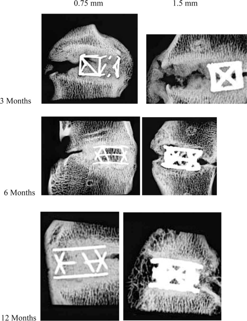
Microradiographs representative of the mean fusion score are shown in Figure 5.
Figure 5.
Microradiographs representative of the mean fusion score for both strut diameter cages at each postoperative follow-up interval.
Histomorphometric Evaluation
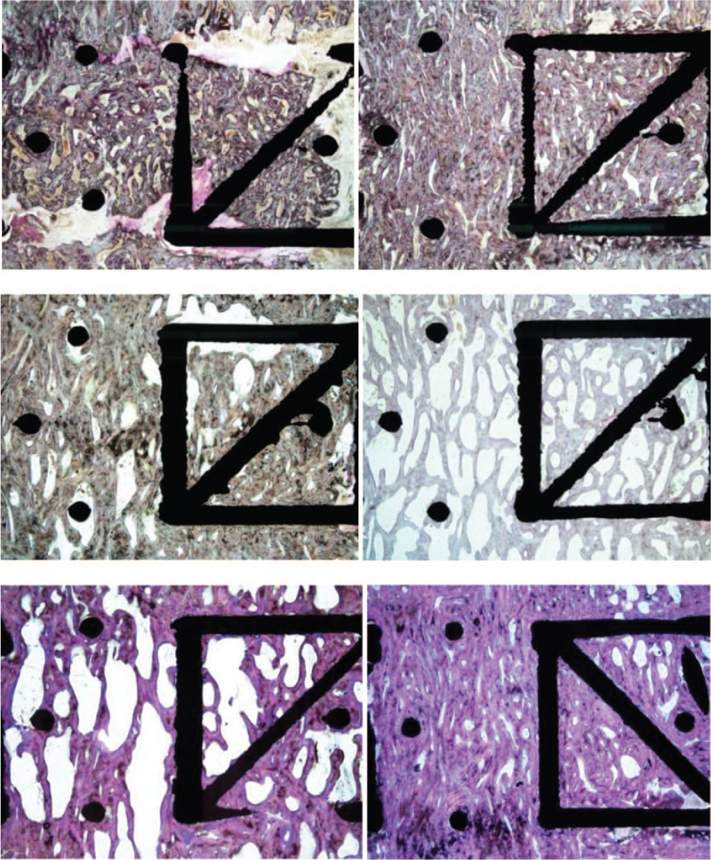
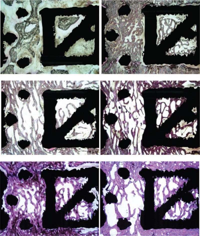
Over time in the area encompassing both the interior of the implant and the adjacent spaces, the average percent of bone increased (P > 0.05) and the fibrous tissue significantly decreased (P < 0.001) in both groups (Table 2). Although there were no significant differences between the 0.75 and 1.5 mm strut diameter groups, the thinner struts were generally associated with greater mineralized bone tissue and less fibrous/chondral tissue than the thicker struts at each postoperative follow-up interval. Figures 6 and 7 demonstrate the least and most amount of mineralized bone for each diameter construct at each time point. Qualitative histological assessments revealed denser bone and less marrow with the thinner strut construct. The trabecular organization and thickness in and around cages with the thinner struts appeared very similar to vertebral bone above and below the cages. In contrast, more 1.5 mm diameter devices had slightly thicker bone at the outer cage perimeter and slightly longer trabecular structures.
TABLE 2.
Histomorphometry Quantitative Results for the Region of Interest that Includes Within and Outside of the Cage
| Treatment | Implant Duration | ROI Within and Outside of Cage | ||
| Percent Bone (%) | Percent Fibrous/Chondral Tissue (%) | Percent Bone Marrow (%) | ||
| Group 1 0.75 mm with autograft | 3 months | 48.73 ± 9.79 | 14.15 ± 7.27 | 37.12 ± 7.61 |
| 6 months | 57.46 ± 8.93 | 2.87 ± 4.00 | 39.68 ± 9.22 | |
| 12 months | 62.36 ± 11.46 | 0.42 ± 0.39 | 37.22 ± 11.66 | |
| Group 2 1.5 mm with autograft | 3 months | 38.65 ± 15.21 | 18.22 ± 10.80 | 43.13 ± 13.23 |
| 6 months | 51.29 ± 10.18 | 1.71 ± 1.80 | 47.00 ± 9.70 | |
| 12 months | 54.68 ± 10.64 | 1.68 ± 2.31 | 43.64 ± 12.27 | |
Data are presented as the mean (±SD). All between-group comparisons P > 0.05.
Figure 6.
Histology at 3, 6, and 12 months for the 0.75 mm diameter strut cage showing sections with the least and most mineralized bone. The top left panel shows the least amount of bone (seen as a grayish purple at low power) and the most amount of soft tissue at 3 months. The top right panel shows more bone with almost no soft tissue other than marrow. At 6 months, the middle left panel shows substantial amount of bone and only a small amount of soft tissue is evident. Increased bone formation is evident in the middle right panel. At 12 months, the bottom left panel shows that bone fill was nearly complete and connectivity was good, although some soft tissue is evident. The bottom right panel shows dense bone at 12 months. Toluidine blue/Paragon stain; original magnification, 7×.
Figure 7.
Histology at 3, 6, and 12 months for the 1.5 mm diameter strut cage. The top left panel shows the fusion result with the least amount of bone (grayish purple) and most amount of soft tissue after 3 months implantation. The top right panel shows more bony trabeculae and almost no soft tissue at 3 months. At 6 months, the middle panel shows some bony trabeculation and a small amount of soft tissue. The middle right section, which represents the best fusion result at 6 months for this implant type, shows more extensive bony trabeculation. The bottom left and right panels both show bony trabeculation at 12 months but with different amounts of bone and bone marrow within the cages. Toluidine blue/Paragon stain; original magnification, 7×.
By 12 months bone mineralization was largely quiescent for both groups.
There was no acute inflammation, chronic inflammation, or wear debris seen in any of the sections for either of the implants at any time.
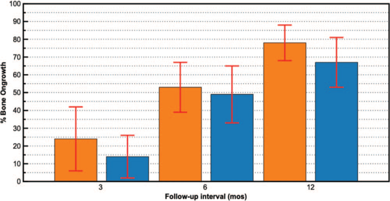
For mean percent bone ongrowth, there was a significant (P < 0.001) increase over time in both groups with no significant differences between groups at any time point (Figure 8).
Figure 8.
Mean (±SD) percent bone ongrowth values at each postoperative follow-up interval for 0.75 mm (orange) and 1.5 mm (blue) diameter strut cages. Average ongrowth scores significantly (P < 0.001 for all comparisons) increased over time for both diameter strut cages compared with previous follow-up intervals.
DISCUSSION
Through the advancements in manufacturing technology, such as 3D printing, spinal interbody implants with advanced structural designs are now being produced. These devices represent a new generation of implants that actively participate in the bone mineralization and fusion consolidation processes. The truss-based design of the devices tested in the current study enables the optimal transfer of compressive and tensile stresses via the struts in a manner that mimics physiologic load transfer.9 The open architecture design consists of an empirically-derived web of trusses that function as a high-strength, lightweight structure with a significant amount of open space to accommodate bone graft and promote osseointegration. This classic architectural form was utilized to maximize the distribution of natural spinal compressive loads in a biomechanically efficient fashion.
The truss implant was engineered with a unique spatial geometry that leverages the mechanobiologic principle of bone functional adaptation, commonly referred to as “Wolff's Law.”14 This principle, which theorizes that bone can adapt over time to mechanical loading, has been comprehensively expatiated and described by Frost as the mechanostat.15–17 Frost postulated that both bone growth and bone loss are precipitated by the local mechanical deformation of bone and that lower load-induced strain amplitudes result in stress shielding and bone resorption, moderate strain amplitudes support bone homeostasis, and higher strain amplitudes promote bone formation.7,18
Several design variables, such as strut diameter, can be adjusted to provide different strain amplitudes within the truss implant, which in turn, may affect bone formation and fusion rate. Our FEA modeling estimated an inverse relationship between truss strut diameter and peak strain, with an approximate 73% lower strain amplitude, on average, for cages with 1.5 mm diameter struts compared with cages with 0.75 mm diameters struts (Figure 2).
The differences in load-induced strain amplitudes and distributions predicted by our FEA model extended to our in vivo ovine study, offering additional validation of the association between strut diameter and bone mineralization and fusion outcomes. For example, we noted significantly higher radiographic fusion scores for cages with 0.75 mm strut diameters, starting as early as 3 months postoperatively, suggesting more rapid osseointegration with a strut diameter in the higher strain-amplitude range. Histomorphometric analysis was confirmatory, showing thinner struts were generally associated with greater mineralized bone tissue and less fibrous/ chondral tissue than the thicker struts at each postoperative follow-up interval. These findings may have important implications for the management of patients with underlying osteoporosis who may have impaired bone metabolism, making fusion consolidation more challenging.
Both cage types demonstrated similar degrees of bone ongrowth over time. This titanium truss-based implant incorporates hierarchical surface roughness, that spans from the macro- to nano-scale, and imparts the implant with inherent topologic features that envelop all the struts, stimulating osteogenic gene expression, differentiation, and matrix production.19–21 This suggests that bone ongrowth and, by extension, cage stability in the joint space may be more a function of titanium surface modifications than load transfer.
In conclusion, using this specific truss-based device in an ovine model, cages with smaller diameter struts exhibited more rapid fusion consolidation and more aggressive osseointegration compared with cages with larger diameters struts. These in vivo findings corroborate and extend simulated FEA models predicting higher peak strain amplitudes in cages with smaller diameter struts. Additional research is warranted to validate these findings in the clinical setting.
Key Points
Designed to provide efficient load distribution, a truss-based interbody fusion device with an advanced structural design was evaluated.
FEA and a confirmatory longitudinal in vivo ovine fusion study were undertaken to determine comparative load-induced strain amplitudes, bone mineralization, and fusion outcomes associated with different diameter struts in the truss implant.
FEA showed an inverse association between strut diameter and peak strain amplitude.
In vivo findings were confirmatory with thinner struts demonstrating faster fusion consolidation, greater mineralized bone, and less fibrous/ chondral tissue than the thicker struts.
Footnotes
The device(s)/drug(s) is/are FDA-approved or approved by corresponding national agency for this indication.
4Web Medical Inc. funds were received in support of this work.
Relevant financial activities outside the submitted work: stocks.
References
- 1.Eck JC, Sharan A, Ghogawala Z, et al. Guideline update for the performance of fusion procedures for degenerative disease of the lumbar spine. Part 7: lumbar fusion for intractable low-back pain without stenosis or spondylolisthesis. J Neurosurg Spine 2014; 21:42–47. [DOI] [PubMed] [Google Scholar]
- 2.Mobbs RJ, Phan K, Malham G, et al. Lumbar interbody fusion: techniques, indications and comparison of interbody fusion options including PLIF, TLIF, MI-TLIF, OLIF/ATP, LLIF and ALIF. J Spine Surg 2015; 1:2–18. [DOI] [PMC free article] [PubMed] [Google Scholar]
- 3.Mummaneni PV, Dhall SS, Eck JC, et al. Guideline update for the performance of fusion procedures for degenerative disease of the lumbar spine. Part 11: interbody techniques for lumbar fusion. J Neurosurg Spine 2014; 21:67–74. [DOI] [PubMed] [Google Scholar]
- 4.Blumenthal SL, Ohnmeiss DD. NASS. Intervertebral cages for degenerative spinal diseases. Spine J 2003; 3:301–309. [DOI] [PubMed] [Google Scholar]
- 5.Kaiser MG, Groff MW, Watters WC, 3rd, et al. Guideline update for the performance of fusion procedures for degenerative disease of the lumbar spine. Part 16: bone graft extenders and substitutes as an adjunct for lumbar fusion. J Neurosurg Spine 2014; 21:106–132. [DOI] [PubMed] [Google Scholar]
- 6.Abjornson C, Brecevich A, Callanan T, et al. ISASS recommendations and coverage criteria for bone graft substitutes used in spinal surgery. Int J Spine Surg 2018; 12:757–771. [DOI] [PMC free article] [PubMed] [Google Scholar]
- 7.Frost HM. Bone's mechanostat: a 2003 update. Anat Rec A Discov Mol Cell Evol Biol 2003; 275:1081–1101. [DOI] [PubMed] [Google Scholar]
- 8.Oftadeh R, Perez-Viloria M, Villa-Camacho JC, et al. Biomechanics and mechanobiology of trabecular bone: a review. J Biomech Eng 2015; 137:0108021–01080215. [DOI] [PMC free article] [PubMed] [Google Scholar]
- 9.Caffrey JP, Cory E, Wong VW, et al. Ex vivo loading of trussed implants for spine fusion induces heterogeneous strains consistent with homeostatic bone mechanobiology. J Biomech 2016; 49:4090–4097. [DOI] [PMC free article] [PubMed] [Google Scholar]
- 10.Turner CH. Three rules for bone adaptation to mechanical stimuli. Bone 1998; 23:399–407. [DOI] [PubMed] [Google Scholar]
- 11.Cullen DM, Smith RT, Akhter MP. Bone-loading response varies with strain magnitude and cycle number. J Appl Physiol (1985) 2001; 91:1971–1976. [DOI] [PubMed] [Google Scholar]
- 12.Khere A, Kiapour A, Seth A, et al. A finite element assessment to compare the biomechanical behaviour of human, sheep and chagma baboon functional spine units. ASME 2007 Summer Bioengineering Conference 2014; Keystone, CO: ASME, 425–426. [Google Scholar]
- 13.Easley NE, Wang M, McGrady LM, et al. Biomechanical and radiographic evaluation of an ovine model for the human lumbar spine. Proc Inst Mech Eng H 2008; 222:915–922. [DOI] [PubMed] [Google Scholar]
- 14.Ruff C, Holt B, Trinkaus E. Who's afraid of the big bad Wolff?: “Wolff's law” and bone functional adaptation. Am J Phys Anthropol 2006; 129:484–498. [DOI] [PubMed] [Google Scholar]
- 15.Frost HM. Skeletal structural adaptations to mechanical usage (SATMU): 2. Redefining Wolff's law: the remodeling problem. Anat Rec 1990; 226:414–422. [DOI] [PubMed] [Google Scholar]
- 16.Frost HM. Skeletal structural adaptations to mechanical usage (SATMU): 1. Redefining Wolff's law: the bone modeling problem. Anat Rec 1990; 226:403–413. [DOI] [PubMed] [Google Scholar]
- 17.Frost HM. Wolff's Law and bone's structural adaptations to mechanical usage: an overview for clinicians. Angle Orthod 1994; 64:175–188. [DOI] [PubMed] [Google Scholar]
- 18.Frost HM. Bone “mass” and the “mechanostat”: a proposal. Anat Rec 1987; 219:1–9. [DOI] [PubMed] [Google Scholar]
- 19.Peng W, Xu L, You J, et al. Selective laser melting of titanium alloy enables osseointegration of porous multi-rooted implants in a rabbit model. Biomed Eng Online 2016; 15:85. [DOI] [PMC free article] [PubMed] [Google Scholar]
- 20.Rao PJ, Pelletier MH, Walsh WR, et al. Spine interbody implants: material selection and modification, functionalization and bioactivation of surfaces to improve osseointegration. Orthop Surg 2014; 6:81–89. [DOI] [PMC free article] [PubMed] [Google Scholar]
- 21.Olivares-Navarrete R, Hyzy SL, Slosar PJ, et al. Implant materials generate different peri-implant inflammatory factors: poly-ether-ether-ketone promotes fibrosis and microtextured titanium promotes osteogenic factors. Spine (Phila Pa 1976) 2015; 40:399–404. [DOI] [PMC free article] [PubMed] [Google Scholar]


